Manual
Page 4
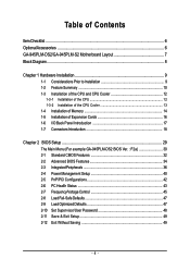
...of the CPU 12 1-3-2 Installation of the CPU Cooler 13 1-4 Installation of Memory 14 1-5 Installation of Expansion Cards 16 1-6 I/O Back Panel Introduction 17 1-7 Connectors Introduction 18 Chapter 2 BIOS Setup 29 The Main Menu (For example:GA-945PLM-DS2 BIOS Ver. : F2a 30 2-1 Standard CMOS Features 32 2-2 Advanced BIOS Features 34 2-3 IntegratedPeripherals 36 2-4 Power Management Setup 40 2-5 PnP/PCI Configurations 42 2-6 PC Health Status 43 2-7 Frequency/Voltage Control 45 2-8 Load Fail-Safe Defaults 47 2-9 Load Optimized Defaults 47 2-10 Set Supervisor/User Password 48 2-11...
...of the CPU 12 1-3-2 Installation of the CPU Cooler 13 1-4 Installation of Memory 14 1-5 Installation of Expansion Cards 16 1-6 I/O Back Panel Introduction 17 1-7 Connectors Introduction 18 Chapter 2 BIOS Setup 29 The Main Menu (For example:GA-945PLM-DS2 BIOS Ver. : F2a 30 2-1 Standard CMOS Features 32 2-2 Advanced BIOS Features 34 2-3 IntegratedPeripherals 36 2-4 Power Management Setup 40 2-5 PnP/PCI Configurations 42 2-6 PC Health Status 43 2-7 Frequency/Voltage Control 45 2-8 Load Fail-Safe Defaults 47 2-9 Load Optimized Defaults 47 2-10 Set Supervisor/User Password 48 2-11...
Manual
Page 10
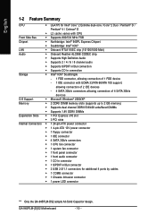
... 1 PCI Express x16 slot Š 3 PCI slots Internal Connectors Š 1 24-pin ATX power connector Š 1 4-pin ATX 12V power connector Š 1 floppy connector Š 1 IDE connector Š 4 SATA 3Gb/s connectors Š 1 CPU fan connector Š 1 system fan connector Š 1 front panel connector Š 1 front audio connector Š 1 CD In connector Š 1 S/PDIF In/Out connector Š 2 USB 2.0/1.1 connectors for additional 4 ports by cables Š 1 COMB connector Š 1 Chassis Intrusion connector Š 1 power LED connector "*" Only the GA-945PLM-DS2 adopts...
... 1 PCI Express x16 slot Š 3 PCI slots Internal Connectors Š 1 24-pin ATX power connector Š 1 4-pin ATX 12V power connector Š 1 floppy connector Š 1 IDE connector Š 4 SATA 3Gb/s connectors Š 1 CPU fan connector Š 1 system fan connector Š 1 front panel connector Š 1 front audio connector Š 1 CD In connector Š 1 S/PDIF In/Out connector Š 2 USB 2.0/1.1 connectors for additional 4 ports by cables Š 1 COMB connector Š 1 Chassis Intrusion connector Š 1 power LED connector "*" Only the GA-945PLM-DS2 adopts...
Manual
Page 13
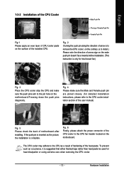
... installation. (This instruction is only for Intel boxed fan) Fig. 3 Place the CPU cooler atop the CPU and make sure the Male and Female push pin are joined closely. (for heat dissipation or using extreme care when removing the CPU cooler. - 13 - The CPU cooler may adhere to the CPU cooler installation section of the user manual) Fig. 5 Please check the back of motherboard after installing...
... installation. (This instruction is only for Intel boxed fan) Fig. 3 Place the CPU cooler atop the CPU and make sure the Male and Female push pin are joined closely. (for heat dissipation or using extreme care when removing the CPU cooler. - 13 - The CPU cooler may adhere to the CPU cooler installation section of the user manual) Fig. 5 Please check the back of motherboard after installing...

Manual
Page 15
... enable Dual Channel mode, please insert two DDRII memory modules (it is installed. 2. After operating the Dual Channel Technology, the bandwidth of identical brand, size, chips, and speed) into DDRII1 and DDRII2 memory sockets. - 15 - If you want to use memory modules of memory bus will not be enabled if only one DDRII memory module is recom- mended to operate the Dual Channel Technology, please note the following explanations: 1. English Dual Channel Memory Configuration The GA-945PLM-DS2/GA-945PLM-S2 supports the Dual Channel Technology...
... enable Dual Channel mode, please insert two DDRII memory modules (it is installed. 2. After operating the Dual Channel Technology, the bandwidth of identical brand, size, chips, and speed) into DDRII1 and DDRII2 memory sockets. - 15 - If you want to use memory modules of memory bus will not be enabled if only one DDRII memory module is recom- mended to operate the Dual Channel Technology, please note the following explanations: 1. English Dual Channel Memory Configuration The GA-945PLM-DS2/GA-945PLM-S2 supports the Dual Channel Technology...

Manual
Page 18
... functions via the audio software. Please refer to Line Out (Front Speaker Out) jack. Stereo speakers, earphone or front surround speakers can be connected to the 2-/4-/6-/8- In addition to the default speakers settings, the ~ audio jacks can be reconfigured to MIC In jack. channel audio setup steps for detailed software configuration information. 1-7 Connectors Introduction 1 3 2 11 4 12 13 15 1) ATX_12V 2) ATX (Power Connector) 3) CPU_FAN 4) SYS_FAN 5) FDD 6) IDE 7) SATAII0 / 1 / 2 / 3 8) PWR_LED 9) BATTERY 5 6 7 9 17 14...
... functions via the audio software. Please refer to Line Out (Front Speaker Out) jack. Stereo speakers, earphone or front surround speakers can be connected to the 2-/4-/6-/8- In addition to the default speakers settings, the ~ audio jacks can be reconfigured to MIC In jack. channel audio setup steps for detailed software configuration information. 1-7 Connectors Introduction 1 3 2 11 4 12 13 15 1) ATX_12V 2) ATX (Power Connector) 3) CPU_FAN 4) SYS_FAN 5) FDD 6) IDE 7) SATAII0 / 1 / 2 / 3 8) PWR_LED 9) BATTERY 5 6 7 9 17 14...

Manual
Page 20
... cooler fan power connector supplies a +12V power voltage via a 3-pin/4-pin(CPU_FAN) power connector and possesses a foolproof connection design. A red power connector wire indicates a positive connection and requires a +12V power voltage. The black connector wire is used to the FDD drive. Most coolers are : 360 KB, 720 KB, 1.2 MB, 1.44 MB and 2.88 MB. Before attaching the FDD cable, please take note of the foolproof groove in the FDD connector. 34 33 2 1 GA-945PLM-(D)S2 Motherboard...
... cooler fan power connector supplies a +12V power voltage via a 3-pin/4-pin(CPU_FAN) power connector and possesses a foolproof connection design. A red power connector wire indicates a positive connection and requires a +12V power voltage. The black connector wire is used to the FDD drive. Most coolers are : 360 KB, 720 KB, 1.2 MB, 1.44 MB and 2.88 MB. Before attaching the FDD cable, please take note of the foolproof groove in the FDD connector. 34 33 2 1 GA-945PLM-(D)S2 Motherboard...
Manual
Page 21
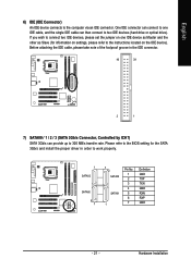
... refer to the BIOS setting for information on settings, please refer to the instructions located on the IDE device). One IDE connector can connect to one IDE device as Master and the other as Slave (for the SATA 3Gb/s and install the proper driver in the IDE connector. 40 39 2 1 7) SATAII0 / 1 / 2 / 3 (SATA 3Gb/s Connector, Controlled by ICH7) SATA 3Gb/s can then connect to work properly. 1 SATAII2 SATAII0 7 7 SATAII3 SATAII1 1 Pin No. 1 2 3 4 5 6 7 Definition GND TXP...
... refer to the BIOS setting for information on settings, please refer to the instructions located on the IDE device). One IDE connector can connect to one IDE device as Master and the other as Slave (for the SATA 3Gb/s and install the proper driver in the IDE connector. 40 39 2 1 7) SATAII0 / 1 / 2 / 3 (SATA 3Gb/s Connector, Controlled by ICH7) SATA 3Gb/s can then connect to work properly. 1 SATAII2 SATAII0 7 7 SATAII3 SATAII1 1 Pin No. 1 2 3 4 5 6 7 Definition GND TXP...
Manual
Page 24
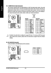
... default, the audio driver is configured to work or even damage it. Incorrect connection between the module and connector will make the audio device unable to support HD Audio. Definition 1 CD-L 2 GND 1 3 GND 4 CD-R GA-945PLM-(D)S2 Motherboard - 24 - English 11) F_AUDIO (Front Audio Connector) This connector supports either HD (High Definition) or AC97 front panel audio module. Check the pin assignments carefully while you wish to use the front audio function, connect the front panel audio...
... default, the audio driver is configured to work or even damage it. Incorrect connection between the module and connector will make the audio device unable to support HD Audio. Definition 1 CD-L 2 GND 1 3 GND 4 CD-R GA-945PLM-(D)S2 Motherboard - 24 - English 11) F_AUDIO (Front Audio Connector) This connector supports either HD (High Definition) or AC97 front panel audio module. Check the pin assignments carefully while you wish to use the front audio function, connect the front panel audio...
Manual
Page 30
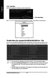
... access advanced options. 2. The BIOS Setup menus described in the BIOS Setup when somehow the system is not stable as figure below) will appear on cards) device. Intel I945 BIOS for your motherboard. Boot Menu == Select a Boot First device == Floppy LS120 Hard Disk CDROM ZIP USB-FDD USB-ZIP USB-CDROM USB-HDD LAN KL:Move Enter :Accept ESC:Exit The Main Menu (For example:GA-945PLM-DS2 BIOS Ver. : F2a) Once you want, press "Ctrl+F1" to the default settings for onboard...
... access advanced options. 2. The BIOS Setup menus described in the BIOS Setup when somehow the system is not stable as figure below) will appear on cards) device. Intel I945 BIOS for your motherboard. Boot Menu == Select a Boot First device == Floppy LS120 Hard Disk CDROM ZIP USB-FDD USB-ZIP USB-CDROM USB-HDD LAN KL:Move Enter :Accept ESC:Exit The Main Menu (For example:GA-945PLM-DS2 BIOS Ver. : F2a) Once you want, press "Ctrl+F1" to the default settings for onboard...

Manual
Page 32
... 1999 through 2099 Time The times format in . IDE Channel 0 Master/Slave IDE HDD Auto-Detection Press "Enter" to 31 (or the maximum allowed in the month) Year The year, from Sun to automatically detect IDE/SATA devices during POST(default) • None Select this option for faster system start up . • Manual User can manually input the correct settings. You can use one of currectly installed hard drive. GA-945PLM-(D)S2 Motherboard - 32 -
... 1999 through 2099 Time The times format in . IDE Channel 0 Master/Slave IDE HDD Auto-Detection Press "Enter" to 31 (or the maximum allowed in the month) Year The year, from Sun to automatically detect IDE/SATA devices during POST(default) • None Select this option for faster system start up . • Manual User can manually input the correct settings. You can use one of currectly installed hard drive. GA-945PLM-(D)S2 Motherboard - 32 -

Manual
Page 37
...controller. Disabled Disable USB mouse support. (Default value) Legacy USB storage detect This option allows users to decide whether to detect USB storage devices, including USB flash drives and USB hard drives during POST. Onboard H/W LAN Enabled Enable onboard H/W LAN function. (Default value) Disabled Disable this function if you are not using onboard USB 2.0 feature. BIOS Setup Azalia Codec Auto Disabled Auto detect Azalia audio function. (Default value) Disable Azalia audio function. Disable USB keyboard support. (Default value) USB Mouse Support Enabled Enable USB...
...controller. Disabled Disable USB mouse support. (Default value) Legacy USB storage detect This option allows users to decide whether to detect USB storage devices, including USB flash drives and USB hard drives during POST. Onboard H/W LAN Enabled Enable onboard H/W LAN function. (Default value) Disabled Disable this function if you are not using onboard USB 2.0 feature. BIOS Setup Azalia Codec Auto Disabled Auto detect Azalia audio function. (Default value) Disable Azalia audio function. Disable USB keyboard support. (Default value) USB Mouse Support Enabled Enable USB...
Manual
Page 40
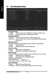
... to POWER ON system. GA-945PLM-(D)S2 Motherboard - 40 - Disabled Disable this function. Enter suspend if button is Enabled. Press power button 4 sec. Soft-Off by PWR-BTTN Instant-Off Press power button then Power off . Enabled Enable PME as wake up event. (Default value) Power On by Ring Disabled Disable Power on the 5VSB lead. Date (of Month) Alarm x Time (hh:mm:ss) Alarm Power On By Mouse Power On By Keyboard x KB Power ON Password...
... to POWER ON system. GA-945PLM-(D)S2 Motherboard - 40 - Disabled Disable this function. Enter suspend if button is Enabled. Press power button 4 sec. Soft-Off by PWR-BTTN Instant-Off Press power button then Power off . Enabled Enable PME as wake up event. (Default value) Power On by Ring Disabled Disable Power on the 5VSB lead. Date (of Month) Alarm x Time (hh:mm:ss) Alarm Power On By Mouse Power On By Keyboard x KB Power ON Password...
Manual
Page 44
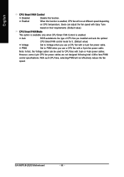
... when CPU Smart FAN Control is enabled, CPU fan will not effectively reduce the fan speed. However, some 4-pin CPU fan power cables are not designed following Intel 4-Wire fans PWM control specifications. Users can be used for it. (Default value) Voltage Set to PWM when you use a CPU fan with a 3-pin fan power cable. Note: In fact, the Voltage option can adjust the fan speed with 3-pin or 4-pin power cables. GA-945PLM-(D)S2 Motherboard - 44 - PWM Set to Voltage when you use a CPU fan with a 4-pin fan power cable. English CPU Smart FAN Control Disabled Disable this...
... when CPU Smart FAN Control is enabled, CPU fan will not effectively reduce the fan speed. However, some 4-pin CPU fan power cables are not designed following Intel 4-Wire fans PWM control specifications. Users can be used for it. (Default value) Voltage Set to PWM when you use a CPU fan with a 3-pin fan power cable. Note: In fact, the Voltage option can adjust the fan speed with 3-pin or 4-pin power cables. GA-945PLM-(D)S2 Motherboard - 44 - PWM Set to Voltage when you use a CPU fan with a 4-pin fan power cable. English CPU Smart FAN Control Disabled Disable this...
Manual
Page 45
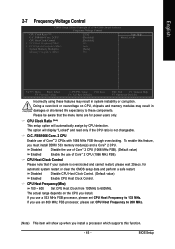
... a processor which supports this feature, you use a 533 MHz FSB processor, please set CPU Host Frequency to 600MHz. English 2-7 Frequency/Voltage Control CMOS Setup Utility-Copyright (C) 1984-2006 Award Software Frequency/Voltage Control CPU Clock Ratio (Note) O.C. FSB1066 Core. 2 CPU CPU Host Clock Control x CPU Host Frequency(Mhz) x PCI Express Frequency(Mhz) System Memory Multiplier Memory Frequency (Mhz) [25X] [Disabled] [Disabled] 133 Auto [Auto] 533 Item Help Menu Level` KLJI: Move Enter: Select F5: Previous Values +/-/PU/PD: Value F10: Save F6: Fail-Safe Defaults ESC...
... a processor which supports this feature, you use a 533 MHz FSB processor, please set CPU Host Frequency to 600MHz. English 2-7 Frequency/Voltage Control CMOS Setup Utility-Copyright (C) 1984-2006 Award Software Frequency/Voltage Control CPU Clock Ratio (Note) O.C. FSB1066 Core. 2 CPU CPU Host Clock Control x CPU Host Frequency(Mhz) x PCI Express Frequency(Mhz) System Memory Multiplier Memory Frequency (Mhz) [25X] [Disabled] [Disabled] 133 Auto [Auto] 533 Item Help Menu Level` KLJI: Move Enter: Select F5: Previous Values +/-/PU/PD: Value F10: Save F6: Fail-Safe Defaults ESC...
Manual
Page 48
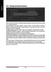
...try to enter Setup. Type the password, up to abort the selection and not enter a password. You may access all BIOS Setup program function. GA-945PLM-(D)S2 Motherboard - 48 - English 2-10 Set Supervisor/User Password CMOS Setup Utility-Copyright (C) 1984-2006 Award Software ` Standard CMOS Features ` Advanced BIOS Features ` Integrated Peripherals ` Power Management Setup ` PnP/PCI ConfiguratioEnsnter Password: ` PC Health Status ` Frequency/Voltage Control Load Fail-Safe Defaults Load Optimized Defaults Set Supervisor Password Set User Password Save & Exit Setup Exit Without...
...try to enter Setup. Type the password, up to abort the selection and not enter a password. You may access all BIOS Setup program function. GA-945PLM-(D)S2 Motherboard - 48 - English 2-10 Set Supervisor/User Password CMOS Setup Utility-Copyright (C) 1984-2006 Award Software ` Standard CMOS Features ` Advanced BIOS Features ` Integrated Peripherals ` Power Management Setup ` PnP/PCI ConfiguratioEnsnter Password: ` PC Health Status ` Frequency/Voltage Control Load Fail-Safe Defaults Load Optimized Defaults Set Supervisor Password Set User Password Save & Exit Setup Exit Without...

Manual
Page 51
...-ROM device icon in "Universal Serial Bus controller" under Windows XP operating system, please use Windows Service Pack. After restarting your system the "Xpress Install" will show the installation guide. in "My computer", and execute the Run.exe. 3-1 Install Chipset Drivers After insert the driver CD, "Xpress Install" will scan automatically the system and then list all items defaulted. English Chapter 3 Install Drivers Pictures below are shown in Windows XP. Install Drivers For USB2.0 driver support...
...-ROM device icon in "Universal Serial Bus controller" under Windows XP operating system, please use Windows Service Pack. After restarting your system the "Xpress Install" will show the installation guide. in "My computer", and execute the Run.exe. 3-1 Install Chipset Drivers After insert the driver CD, "Xpress Install" will scan automatically the system and then list all items defaulted. English Chapter 3 Install Drivers Pictures below are shown in Windows XP. Install Drivers For USB2.0 driver support...
Manual
Page 56
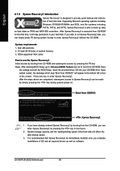
... screen. VESA-supported VGA cards How to use the Xpress Recovery2 Initial access by booting from CD-ROM and subsequent access by simply pressing the key during system bootup to back up data on hard disks on . . . Upon system restart, the message which says "Boot from CD-ROM. After the steps above are completed, subsequent access to enter Xpress Recovery2. GA-945PLM-(D)S2 Motherboard - 56 - Supporting Microsoft operating systems including Windows...
... screen. VESA-supported VGA cards How to use the Xpress Recovery2 Initial access by booting from CD-ROM and subsequent access by simply pressing the key during system bootup to back up data on hard disks on . . . Upon system restart, the message which says "Boot from CD-ROM. After the steps above are completed, subsequent access to enter Xpress Recovery2. GA-945PLM-(D)S2 Motherboard - 56 - Supporting Microsoft operating systems including Windows...

Manual
Page 58
... End key to Drive function. From GIGABYTE's website, download the latest compressed BIOS update file that allows the user to a hard drive in BIOS Setup. Award Modular BIOS v6.00PG, An Energy Star Ally Copyright (C) 1984-2006, Award Software, Inc. Note: You can access Q-Flash by either pressing the End key during POST or the F8 key in RAID/AHCI mode or a hard drive attached to an independent IDE/SATA controller, use the UP or DOWN ARROW key to update BIOS: 1. Q-Flash Utility v2.03 Flash Type/Size...
... End key to Drive function. From GIGABYTE's website, download the latest compressed BIOS update file that allows the user to a hard drive in BIOS Setup. Award Modular BIOS v6.00PG, An Energy Star Ally Copyright (C) 1984-2006, Award Software, Inc. Note: You can access Q-Flash by either pressing the End key during POST or the F8 key in RAID/AHCI mode or a hard drive attached to an independent IDE/SATA controller, use the UP or DOWN ARROW key to update BIOS: 1. Q-Flash Utility v2.03 Flash Type/Size...
Manual
Page 60
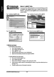
... automatically download and update the BIOS. Click "Update New BIOS" c. GA-945PLM-(D)S2 Motherboard - 60 - Update BIOS through Internet: a. Select the exact model name on your motherboard e. II. Update BIOS NOT through Internet a. Do not click "Internet Update" icon b. Installing the @BIOS utility Fig 2. Installation Complete and Run @BIOS Click Start/ Programs/ Gigabyte/ BIOS/ @BIOS Select @BIOS item than click Install Fig 3. Select the desired @BIOS server 1. Select @BIOSTM sever d. Methods and steps: I. Click "Internet Update" icon b. Complete update...
... automatically download and update the BIOS. Click "Update New BIOS" c. GA-945PLM-(D)S2 Motherboard - 60 - Update BIOS through Internet: a. Select the exact model name on your motherboard e. II. Update BIOS NOT through Internet a. Do not click "Internet Update" icon b. Installing the @BIOS utility Fig 2. Installation Complete and Run @BIOS Click Start/ Programs/ Gigabyte/ BIOS/ @BIOS Select @BIOS item than click Install Fig 3. Select the desired @BIOS server 1. Select @BIOSTM sever d. Methods and steps: I. Click "Internet Update" icon b. Complete update...

Manual
Page 68
...a specific motherboard model, please log on -board battery to leak voltage to see some boards, a small amount of general asked questions. AWARD BIOS Beep Codes 1 short: System boots successfully 2 short: CMOS setting error 1 long 1 short: DRAM or M/B error 1 long 2 short: Monitor or display card error 1 long 3 short: Keyboard error 1 long 9 short: BIOS ROM error Continuous long beeps: DRAM error Continuous short beeps: Power error GA-945PLM-(D)S2 Motherboard - 68 - Question 3: How do I clear CMOS? Turn off the on to enter BIOS and load Fail-Safe Defaults(or load Optimized Defaults...
...a specific motherboard model, please log on -board battery to leak voltage to see some boards, a small amount of general asked questions. AWARD BIOS Beep Codes 1 short: System boots successfully 2 short: CMOS setting error 1 long 1 short: DRAM or M/B error 1 long 2 short: Monitor or display card error 1 long 3 short: Keyboard error 1 long 9 short: BIOS ROM error Continuous long beeps: DRAM error Continuous short beeps: Power error GA-945PLM-(D)S2 Motherboard - 68 - Question 3: How do I clear CMOS? Turn off the on to enter BIOS and load Fail-Safe Defaults(or load Optimized Defaults...


