Manual
Page 4
... CPU 12 1-3-2 Installation of the Cooler 13 1-4 Installation of Memory 14 1-5 Installation of Expansion Cards 16 1-6 I/O Back Panel Introduction 17 1-7 Connectors Introduction 18 Chapter 2 BIOS Setup 29 The Main Menu (For example: GA-945PL-DS3P BIOS Ver.: E1 30 2-1 Standard CMOS Features 32 2-2 Advanced BIOS Features 34 2-3 IntegratedPeripherals 36 2-4 Power Management Setup 39 2-5 PnP/PCI Configurations 41 2-6 PC Health Status 42 2-7 MB Intelligent Tweaker(M.I.T 44 2-8 Load Fail-Safe Defaults 47 2-9 Load Optimized Defaults 47 2-10 Set Supervisor/User Password...
... CPU 12 1-3-2 Installation of the Cooler 13 1-4 Installation of Memory 14 1-5 Installation of Expansion Cards 16 1-6 I/O Back Panel Introduction 17 1-7 Connectors Introduction 18 Chapter 2 BIOS Setup 29 The Main Menu (For example: GA-945PL-DS3P BIOS Ver.: E1 30 2-1 Standard CMOS Features 32 2-2 Advanced BIOS Features 34 2-3 IntegratedPeripherals 36 2-4 Power Management Setup 39 2-5 PnP/PCI Configurations 41 2-6 PC Health Status 42 2-7 MB Intelligent Tweaker(M.I.T 44 2-8 Load Fail-Safe Defaults 47 2-9 Load Optimized Defaults 47 2-10 Set Supervisor/User Password...
Manual
Page 10
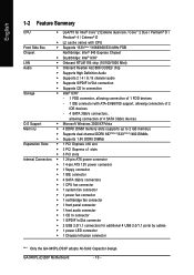
...connection of 4 SATA 3Gb/s devices O.S Support Š Microsoft Windows 2000/XP/Vista Memory Š 4 DDRII DIMM memory slots (supports up to 2 GB memory) Š Supports dual channel DDRII 667(Note 2)/533(Note 3)/400 DIMMs Š Supports 1.8V DDRII DIMMs Expanstion Slots Š 1 PCI Express x16 slot Š 3 PCI Express x1 slots Š 3 PCI slots Internal Connectors Š 1 24-pin ATX power connector Š 1 4-pin ATX 12V power connector Š 1 floppy connector Š 1 IDE connector Š 4 SATA 3Gb/s connectors Š 1 CPU fan connector Š 1 system fan connector...
...connection of 4 SATA 3Gb/s devices O.S Support Š Microsoft Windows 2000/XP/Vista Memory Š 4 DDRII DIMM memory slots (supports up to 2 GB memory) Š Supports dual channel DDRII 667(Note 2)/533(Note 3)/400 DIMMs Š Supports 1.8V DDRII DIMMs Expanstion Slots Š 1 PCI Express x16 slot Š 3 PCI Express x1 slots Š 3 PCI slots Internal Connectors Š 1 24-pin ATX power connector Š 1 4-pin ATX 12V power connector Š 1 floppy connector Š 1 IDE connector Š 4 SATA 3Gb/s connectors Š 1 CPU fan connector Š 1 system fan connector...
Manual
Page 11
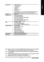
... port Š 1 serial port Š 4 USB 2.0/1.1 port Š 1 RJ-45 ports Š 6 audio jacks (Line In / Line Out / MIC In/Surround Speaker Out (Rear Speaker Out)/Center/Subwoofer Speaker Out/Side Speaker Out) I/O Control Š IT8718 chip Hardware Monitor Š System voltage detection Š CPU temperature detection Š CPU / Power / System fan speed detection Š CPU warning temperature Š CPU / Power / System fan failure warning Š Supports CPU Smart Fan function BIOS Š 1 4 Mbit flash ROM Š Use of a CoreTM 2 CPU with DDRII 533 (or above) memory...
... port Š 1 serial port Š 4 USB 2.0/1.1 port Š 1 RJ-45 ports Š 6 audio jacks (Line In / Line Out / MIC In/Surround Speaker Out (Rear Speaker Out)/Center/Subwoofer Speaker Out/Side Speaker Out) I/O Control Š IT8718 chip Hardware Monitor Š System voltage detection Š CPU temperature detection Š CPU / Power / System fan speed detection Š CPU warning temperature Š CPU / Power / System fan failure warning Š Supports CPU Smart Fan function BIOS Š 1 4 Mbit flash ROM Š Use of a CoreTM 2 CPU with DDRII 533 (or above) memory...
Manual
Page 13
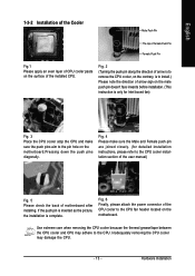
... joined closely. (for detailed installation instructions, please refer to the CPU fan header located on the surface of the installed CPU. Fig. 6 Finally, please attach the power connector of the CPU cooler to the CPU cooler installation section of the user manual) Fig. 5 Please check the back of motherboard after installing. Hardware Installation Fig. 4 Please make sure the push pins aim to the CPU. Inadequately removing the CPU cooler may adhere to...
... joined closely. (for detailed installation instructions, please refer to the CPU fan header located on the surface of the installed CPU. Fig. 6 Finally, please attach the power connector of the CPU cooler to the CPU cooler installation section of the user manual) Fig. 5 Please check the back of motherboard after installing. Hardware Installation Fig. 4 Please make sure the push pins aim to the CPU. Inadequately removing the CPU cooler may adhere to...
Manual
Page 15
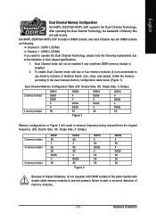
... DDRII4 X SS X DS/SS SS SS SS Because of chipset limitations, do not populate both DIMM sockets of the same channel with two or four memory modules (it is installed. 2. English Dual Channel Memory Configuration GA-945PL-DS3P/GA-945PL-S3P supports the Dual Channel Technology. To enable Dual Channel mode with double-sided memory modules to prevent system's failure to the limitation of identical brand, size, chips, and speed), install the memory according to the dual channel memory configuration table below (Figure 1).
... DDRII4 X SS X DS/SS SS SS SS Because of chipset limitations, do not populate both DIMM sockets of the same channel with two or four memory modules (it is installed. 2. English Dual Channel Memory Configuration GA-945PL-DS3P/GA-945PL-S3P supports the Dual Channel Technology. To enable Dual Channel mode with double-sided memory modules to prevent system's failure to the limitation of identical brand, size, chips, and speed), install the memory according to the dual channel memory configuration table below (Figure 1).
Manual
Page 18
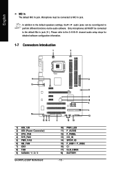
... MIC In jack. Only microphones still MUST be connected to the default Mic In jack ( ). In addition to the default speakers settings, the ~ audio jacks can be reconfigured to the 2-/4-/6-/8- channel audio setup steps for detailed software configuration information. 1-7 Connectors Introduction 1 3 6 11 16 13 14 4 1) ATX_12V 2) ATX (Power Connector) 3) CPU_FAN 4) SYS_FAN 5) PWR_FAN 6) NB_FAN 7) IDE1 8) FDD 9) SATAII0 / 1 / 2 / 3 GA-945PL-(D)S3P Motherboard 2 5 17 18 9 7 12 8 15 10 10) PWR_LED 11) F_AUDIO...
... MIC In jack. Only microphones still MUST be connected to the default Mic In jack ( ). In addition to the default speakers settings, the ~ audio jacks can be reconfigured to the 2-/4-/6-/8- channel audio setup steps for detailed software configuration information. 1-7 Connectors Introduction 1 3 6 11 16 13 14 4 1) ATX_12V 2) ATX (Power Connector) 3) CPU_FAN 4) SYS_FAN 5) PWR_FAN 6) NB_FAN 7) IDE1 8) FDD 9) SATAII0 / 1 / 2 / 3 GA-945PL-(D)S3P Motherboard 2 5 17 18 9 7 12 8 15 10 10) PWR_LED 11) F_AUDIO...
Manual
Page 20
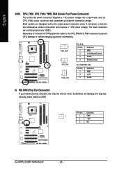
... direction, the chip fan will damage the chip fan. (Usually black cable is the ground wire (GND). English 3/4/5) CPU_FAN / SYS_FAN / PWR_FAN (Cooler Fan Power Connector) The cooler fan power connector supplies a +12V power voltage via a 3-pin/4-pin (only for CPU_FAN) power connector and possesses a foolproof connection design. Sometimes will not work. Most coolers are designed with color-coded power connector wires. A red power connector wire indicates a positive connection and requires a +12V power voltage. Definition 1 1 GND 2 +12V 3 NC GA-945PL-(D)S3P Motherboard - 20...
... direction, the chip fan will damage the chip fan. (Usually black cable is the ground wire (GND). English 3/4/5) CPU_FAN / SYS_FAN / PWR_FAN (Cooler Fan Power Connector) The cooler fan power connector supplies a +12V power voltage via a 3-pin/4-pin (only for CPU_FAN) power connector and possesses a foolproof connection design. Sometimes will not work. Most coolers are designed with color-coded power connector wires. A red power connector wire indicates a positive connection and requires a +12V power voltage. Definition 1 1 GND 2 +12V 3 NC GA-945PL-(D)S3P Motherboard - 20...
Manual
Page 21
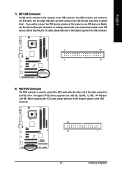
... IDE device as Master and the other end of FDD drives supported are: 360 KB, 720 KB, 1.2 MB, 1.44 MB and 2.88 MB. Hardware Installation One IDE connector can connect to the instructions located on one IDE cable, and the single IDE cable can then connect to the computer via an IDE connector. If you wish to connect two IDE devices, please set the jumper on the IDE device). English 7) IDE1 (IDE Connector) An IDE device connects to two IDE devices (hard drive...
... IDE device as Master and the other end of FDD drives supported are: 360 KB, 720 KB, 1.2 MB, 1.44 MB and 2.88 MB. Hardware Installation One IDE connector can connect to the instructions located on one IDE cable, and the single IDE cable can then connect to the computer via an IDE connector. If you wish to connect two IDE devices, please set the jumper on the IDE device). English 7) IDE1 (IDE Connector) An IDE device connects to two IDE devices (hard drive...
Manual
Page 22
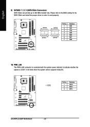
... system enters suspend mode(S1). SATAII0 7 17 SATAII2 1 1 71 7 SATAII1 SATAII3 Pin No. 1 2 3 4 5 6 7 Definition GND TXP TXN GND RXN RXP GND 10) PWR_LED The PWR_LED connector is on/off. GA-945PL-(D)S3P Motherboard - 22 - Please refer to the BIOS setting for the SATA 3Gb/s and install the proper driver in order to indicate whether the system is connected with the system power indicator to work properly...
... system enters suspend mode(S1). SATAII0 7 17 SATAII2 1 1 71 7 SATAII1 SATAII3 Pin No. 1 2 3 4 5 6 7 Definition GND TXP TXN GND RXN RXP GND 10) PWR_LED The PWR_LED connector is on/off. GA-945PL-(D)S3P Motherboard - 22 - Please refer to the BIOS setting for the SATA 3Gb/s and install the proper driver in order to indicate whether the system is connected with the system power indicator to work properly...
Manual
Page 24
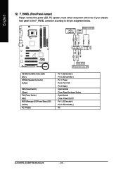
... panel to the F_PANEL connector according to the pin assignment below. Message LED/ Power/ Sleep LED Speaker Connector Power Switch MSG+ MSG- PW+ PWSPEAK+ SPEAK- 2 20 1 19 HD+ HD- Pin 3: NC Pin 4: Data(-) Open: Normal Close: Reset Hardware System Open: Normal Close: Power On/Off Pin 1: LED anode(+) Pin 2: LED cathode(-) NC GA-945PL-(D)S3P Motherboard - 24 - RESRES+ NC HD (IDE Hard Disk Active LED) (Blue) SPEAK (Speaker Connector) (Amber) RES (Reset Switch) (Green) PW (Power Switch) (Red) MSG (Message LED/Power/Sleep LED) (Yellow) NC ( Purple) Reset Switch IDE Hard Disk...
... panel to the F_PANEL connector according to the pin assignment below. Message LED/ Power/ Sleep LED Speaker Connector Power Switch MSG+ MSG- PW+ PWSPEAK+ SPEAK- 2 20 1 19 HD+ HD- Pin 3: NC Pin 4: Data(-) Open: Normal Close: Reset Hardware System Open: Normal Close: Power On/Off Pin 1: LED anode(+) Pin 2: LED cathode(-) NC GA-945PL-(D)S3P Motherboard - 24 - RESRES+ NC HD (IDE Hard Disk Active LED) (Blue) SPEAK (Speaker Connector) (Amber) RES (Reset Switch) (Green) PW (Power Switch) (Red) MSG (Message LED/Power/Sleep LED) (Yellow) NC ( Purple) Reset Switch IDE Hard Disk...
Manual
Page 32
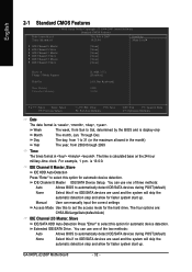
... IDE/SATA devices during POST(default) Select this option for faster system start up . Extended IDE/SATA Drive. English 2-1 Standard CMOS Features Date (mm:dd:yy) Time (hh:mm:ss) CMOS Setup Utility-Copyright (C) 1984-2007 Award Software Standard CMOS Features Thu, Feb 8 2007 18:25:04 Item Help Menu Level` ` IDE Channel 0 Master ` IDE Channel 0 Slave ` IDE Channel 2 Master ` IDE Channel 2 Slave ` IDE Channel 3 Master ` IDE Channel 3 Slave [None] [None] [None] [None] [None] [None] Drive A Floppy 3 Mode Support Halt On Base Memory Extended Memory [1.44M, 3.5"] [Disabled...
... IDE/SATA devices during POST(default) Select this option for faster system start up . Extended IDE/SATA Drive. English 2-1 Standard CMOS Features Date (mm:dd:yy) Time (hh:mm:ss) CMOS Setup Utility-Copyright (C) 1984-2007 Award Software Standard CMOS Features Thu, Feb 8 2007 18:25:04 Item Help Menu Level` ` IDE Channel 0 Master ` IDE Channel 0 Slave ` IDE Channel 2 Master ` IDE Channel 2 Slave ` IDE Channel 3 Master ` IDE Channel 3 Slave [None] [None] [None] [None] [None] [None] Drive A Floppy 3 Mode Support Halt On Base Memory Extended Memory [1.44M, 3.5"] [Disabled...

Manual
Page 37
... Disabled Enable USB 2.0 Controller. (Default value) Disable USB 2.0 Controller. English USB Controller Enabled Enable USB Controller. (Default value) Disabled Disable USB Controller. SMART LAN (LAN Cable Diagnostic Function) CMOS Setup Utility-Copyright (C) 1984-2007 Award Software SMART LAN Start detecting at Port..... Refer to detect USB storage devices, including USB flash drives and USB hard drives during POST. USB Keyboard Support Enabled Enable USB Keyboard Support. Disabled Disable USB Mouse Support. (Default value) Legacy USB storage detect This option allows users...
... Disabled Enable USB 2.0 Controller. (Default value) Disable USB 2.0 Controller. English USB Controller Enabled Enable USB Controller. (Default value) Disabled Disable USB Controller. SMART LAN (LAN Cable Diagnostic Function) CMOS Setup Utility-Copyright (C) 1984-2007 Award Software SMART LAN Start detecting at Port..... Refer to detect USB storage devices, including USB flash drives and USB hard drives during POST. USB Keyboard Support Enabled Enable USB Keyboard Support. Disabled Disable USB Mouse Support. (Default value) Legacy USB storage detect This option allows users...
Manual
Page 42
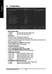
... FAN Speed (RPM) Detect CPU/POWER/SYSTEM Fan speed status automatically. GA-945PL-(D)S3P Motherboard - 42 - Monitor CPU temperature at 70oC / 158oF. Monitor CPU temperature at next boot. English 2-6 PC Health Status CMOS Setup Utility-Copyright (C) 1984-2007 Award Software PC Health Status Reset Case Open Status Case Opened Vcore DDR18V +3.3V +12V Current CPU Temperature Current CPU FAN Speed Current POWER FAN Speed Current SYSTEM FAN Speed CPU Warning Temperature CPU FAN Fail Warning POWER FAN Fail Warning SYSTEM FAN Fail Warning CPU Smart FAN Control CPU Smart FAN Mode [Disabled...
... FAN Speed (RPM) Detect CPU/POWER/SYSTEM Fan speed status automatically. GA-945PL-(D)S3P Motherboard - 42 - Monitor CPU temperature at 70oC / 158oF. Monitor CPU temperature at next boot. English 2-6 PC Health Status CMOS Setup Utility-Copyright (C) 1984-2007 Award Software PC Health Status Reset Case Open Status Case Opened Vcore DDR18V +3.3V +12V Current CPU Temperature Current CPU FAN Speed Current POWER FAN Speed Current SYSTEM FAN Speed CPU Warning Temperature CPU FAN Fail Warning POWER FAN Fail Warning SYSTEM FAN Fail Warning CPU Smart FAN Control CPU Smart FAN Mode [Disabled...
Manual
Page 48
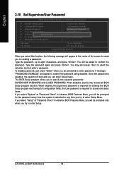
... to enter Setup Menu. Type the password, up to specify two separate passwords: SUPERVISOR PASSWORD and a USER PASSWORD. The BIOS Setup program allows you to eight characters, and press . When disabled, anyone may also press to enter password. GA-945PL-(D)S3P Motherboard - 48 - English 2-10 Set Supervisor/User Password CMOS Setup Utility-Copyright (C) 1984-2007 Award Software ` Standard CMOS Features ` Advanced BIOS Features ` Integrated Peripherals ` Power Management Setup ` PnP/PCI ConfigurationEsnter Password: ` PC Health Status ` MB Intelligent Tweaker(M.I.T.) Load Fail-Safe...
... to enter Setup Menu. Type the password, up to specify two separate passwords: SUPERVISOR PASSWORD and a USER PASSWORD. The BIOS Setup program allows you to eight characters, and press . When disabled, anyone may also press to enter password. GA-945PL-(D)S3P Motherboard - 48 - English 2-10 Set Supervisor/User Password CMOS Setup Utility-Copyright (C) 1984-2007 Award Software ` Standard CMOS Features ` Advanced BIOS Features ` Integrated Peripherals ` Power Management Setup ` PnP/PCI ConfigurationEsnter Password: ` PC Health Status ` MB Intelligent Tweaker(M.I.T.) Load Fail-Safe...

Manual
Page 49
... CMOS Type "Y" will quit the Setup Utility and save the user setup value to RTC CMOS. English 2-11 Save & Exit Setup CMOS Setup Utility-Copyright (C) 1984-2007 Award Software ` Standard CMOS Features Load Fail-Safe Defaults ` Advanced BIOS Features Load Optimized Defaults ` Integrated Peripherals Set Supervisor Password ` Power Management Setup Save to CMOS and EXIT (SYe/tNU)?seYr Password ` PnP/PCI Configurations Save & Exit Setup ` PC Health Status Exit Without Saving ` MB Intelligent Tweaker(M.I .T.) ESC: Quit F8: Q-Flash Load Fail-Safe Defaults Load Optimized Defaults...
... CMOS Type "Y" will quit the Setup Utility and save the user setup value to RTC CMOS. English 2-11 Save & Exit Setup CMOS Setup Utility-Copyright (C) 1984-2007 Award Software ` Standard CMOS Features Load Fail-Safe Defaults ` Advanced BIOS Features Load Optimized Defaults ` Integrated Peripherals Set Supervisor Password ` Power Management Setup Save to CMOS and EXIT (SYe/tNU)?seYr Password ` PnP/PCI Configurations Save & Exit Setup ` PC Health Status Exit Without Saving ` MB Intelligent Tweaker(M.I .T.) ESC: Quit F8: Q-Flash Load Fail-Safe Defaults Load Optimized Defaults...
Manual
Page 51
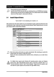
... drivers that recommended to install all items defaulted. Please remove the question mark and restart the system (System will restart your system automatically. Insert the driver CD-title that you can press "Xpress Install" to install. After restarting your CD-ROM drive, the driver CD-title will show the installation guide. Some device drivers will auto-detect the right USB2.0 driver). - 51 - Install Drivers After install Windows Service Pack, it will auto start...
... drivers that recommended to install all items defaulted. Please remove the question mark and restart the system (System will restart your system automatically. Insert the driver CD-title that you can press "Xpress Install" to install. After restarting your CD-ROM drive, the driver CD-title will show the installation guide. Some device drivers will auto-detect the right USB2.0 driver). - 51 - Install Drivers After install Windows Service Pack, it will auto start...
Manual
Page 56
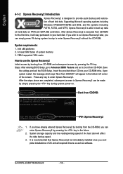
... installations of OS and all required drivers as well as software. If you wish to back up data on hard disks on . . . System requirements: 1. VESA-supported VGA cards How to startup XpressRecovery2..... Press any key to use the Xpress Recovery2 Initial access by booting from the CD-ROM, you can enter Xpress Recovery2 by pressing the F9 key: Steps: After entering BIOS Setup, go to Advanced BIOS Feature and set...
... installations of OS and all required drivers as well as software. If you wish to back up data on hard disks on . . . System requirements: 1. VESA-supported VGA cards How to startup XpressRecovery2..... Press any key to use the Xpress Recovery2 Initial access by booting from the CD-ROM, you can enter Xpress Recovery2 by pressing the F9 key: Steps: After entering BIOS Setup, go to Advanced BIOS Feature and set...
Manual
Page 58
...-DOS or Windows.Embedded in RAID/AHCI mode or a hard drive attached to an independent IDE/SATA controller, use the Save BIOS to access Q-Flash. b. Extract the file and save the new BIOS file (e.g. 9plds3p.F1) to back up the current BIOS file, use the End key during POST or the F8 key in system malfunction. If you from Drive Sa0vefilBeI(Os)SfotounDdrive EnteFr l:oRppuyn A :Move ESC:Reset :Power Off HDD 0-0 Total size : 0 F5 : Refresh GA-945PL-(D)S3P Motherboard Free size : 0 DEL : Delete...
...-DOS or Windows.Embedded in RAID/AHCI mode or a hard drive attached to an independent IDE/SATA controller, use the Save BIOS to access Q-Flash. b. Extract the file and save the new BIOS file (e.g. 9plds3p.F1) to back up the current BIOS file, use the End key during POST or the F8 key in system malfunction. If you from Drive Sa0vefilBeI(Os)SfotounDdrive EnteFr l:oRppuyn A :Move ESC:Reset :Power Off HDD 0-0 Total size : 0 F5 : Refresh GA-945PL-(D)S3P Motherboard Free size : 0 DEL : Delete...

Manual
Page 60
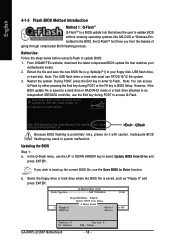
... motherboard e. Update BIOS NOT through Internet a. e. Complete update process following the instruction. Methods and steps: I. Click "Update New BIOS" icon c. Click "Update New BIOS" c. d. Please search for BIOS unzip file, downloading from internet or any other methods (such as: 9plds3p.F1). GA-945PL-(D)S3P Motherboard - 60 - English Method 2 : @BIOSTM Utility If you do not have a DOS startup disk, we recommend that you use the new @BIOS utility. @BIOS allows users to download the latest version...
... motherboard e. Update BIOS NOT through Internet a. e. Complete update process following the instruction. Methods and steps: I. Click "Update New BIOS" icon c. Click "Update New BIOS" c. d. Please search for BIOS unzip file, downloading from internet or any other methods (such as: 9plds3p.F1). GA-945PL-(D)S3P Motherboard - 60 - English Method 2 : @BIOSTM Utility If you do not have a DOS startup disk, we recommend that you use the new @BIOS utility. @BIOS allows users to download the latest version...

Manual
Page 67
...boots successfully 2 short: CMOS setting error 1 long 1 short: DRAM or M/B error 1 long 2 short: Monitor or display card error 1 long 3 short: Keyboard error 1 long 9 short: BIOS ROM error Continuous long beeps: DRAM error Continuous short beeps: Power error - 67 - English 4-2 Troubleshooting Below is a collection of general asked questions based on a specific motherboard model, please log on . Questions 2: Why is the light of my keyboard/optical mouse still on after entering BIOS menu and you will be able to MB again and turn on power. 6. Answer: If your board doesn't have such jumper...
...boots successfully 2 short: CMOS setting error 1 long 1 short: DRAM or M/B error 1 long 2 short: Monitor or display card error 1 long 3 short: Keyboard error 1 long 9 short: BIOS ROM error Continuous long beeps: DRAM error Continuous short beeps: Power error - 67 - English 4-2 Troubleshooting Below is a collection of general asked questions based on a specific motherboard model, please log on . Questions 2: Why is the light of my keyboard/optical mouse still on after entering BIOS menu and you will be able to MB again and turn on power. 6. Answer: If your board doesn't have such jumper...


