Manual
Page 1
GA-945PL-S3G LGA775 socket motherboard for Intel® CoreTM processor family/ Intel® Pentium® processor family/Intel® Celeron® processor family User's Manual Rev. 1001 12ME-945PLS3G-1001R
GA-945PL-S3G LGA775 socket motherboard for Intel® CoreTM processor family/ Intel® Pentium® processor family/Intel® Celeron® processor family User's Manual Rev. 1001 12ME-945PLS3G-1001R

Manual
Page 2
Motherboard GA-945PL-S3G Sept. 21, 2007 Motherboard GA-945PL-S3G Sept. 21, 2007
Motherboard GA-945PL-S3G Sept. 21, 2007 Motherboard GA-945PL-S3G Sept. 21, 2007
Manual
Page 3
...be reproduced, copied, translated, transmitted, or published in the use GIGABYTE's unique features, read or download the information on/from the Support\Motherboard\Technology Guide page on your motherboard revision before updating motherboard BIOS, drivers, or when looking for technical information. is 1.0....information, carefully read the User's Manual. „ For instructions on how to GIGABYTE UNITED INC. The logo is the property of GIGABYTE branded motherboards. Check your motherboard looks like this manual are legally registered to assist in any means without prior ...
...be reproduced, copied, translated, transmitted, or published in the use GIGABYTE's unique features, read or download the information on/from the Support\Motherboard\Technology Guide page on your motherboard revision before updating motherboard BIOS, drivers, or when looking for technical information. is 1.0....information, carefully read the User's Manual. „ For instructions on how to GIGABYTE UNITED INC. The logo is the property of GIGABYTE branded motherboards. Check your motherboard looks like this manual are legally registered to assist in any means without prior ...
Manual
Page 4
Table of Contents Box Contents ...6 OptionalItems ...6 GA-945PL-S3G Motherboard Layout 7 Block Diagram ...8 Chapter 1 Hardware Installation 9 1-1 Installation Precautions 9 1-2 Product Specifications 10 1-3 Installing the CPU and CPU Cooler 13 1-3-1 Installing the CPU 13 1-3-2 Installing the CPU ...
Table of Contents Box Contents ...6 OptionalItems ...6 GA-945PL-S3G Motherboard Layout 7 Block Diagram ...8 Chapter 1 Hardware Installation 9 1-1 Installation Precautions 9 1-2 Product Specifications 10 1-3 Installing the CPU and CPU Cooler 13 1-3-1 Installing the CPU 13 1-3-2 Installing the CPU ...
Manual
Page 6
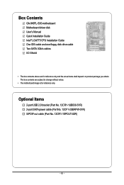
Box Contents GA-945PL-S3G motherboard Motherboard driver disk User's Manual Quick Installation Guide Intel® LGA775 CPU Installation Guide One IDE cable and one floppy disk drive cable Two SATA 3Gb/s cables I/O Shield • The box contents above are subject to change without notice. • The motherboard image is for reference only and the actual items...
Box Contents GA-945PL-S3G motherboard Motherboard driver disk User's Manual Quick Installation Guide Intel® LGA775 CPU Installation Guide One IDE cable and one floppy disk drive cable Two SATA 3Gb/s cables I/O Shield • The box contents above are subject to change without notice. • The motherboard image is for reference only and the actual items...

Manual
Page 7
GA-945PL-S3G Motherboard Layout KB_MS ATX_12V LGA775 CPU_FAN COMA LPT R_USB ATX IDE DDRII1 GA-945PL-S3G DDRII2 PWR_LED F_PANEL LAN USB AUDIO F_AUDIO RTL8111B IT8718 CODEC PCIE_1 PCIE_16 PCIE_2 PCIE_3 PCI1 CD_IN SPDIF_O PCI2 PCI3 Intel® 945 MBIOS Intel® ICH7 SATAII2 BAT SATAII3 CLR_CMOS F_USB1 F_USB2 SATAII0 SATAII1 FDD CI SYS_FAN - 7 -
GA-945PL-S3G Motherboard Layout KB_MS ATX_12V LGA775 CPU_FAN COMA LPT R_USB ATX IDE DDRII1 GA-945PL-S3G DDRII2 PWR_LED F_PANEL LAN USB AUDIO F_AUDIO RTL8111B IT8718 CODEC PCIE_1 PCIE_16 PCIE_2 PCIE_3 PCI1 CD_IN SPDIF_O PCI2 PCI3 Intel® 945 MBIOS Intel® ICH7 SATAII2 BAT SATAII3 CLR_CMOS F_USB1 F_USB2 SATAII0 SATAII1 FDD CI SYS_FAN - 7 -
Manual
Page 9
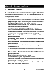
... - Hardware Installation These stickers are required for warranty validation. • Always remove the AC power by unplugging the power cord from the motherboard, make sure the power supply has been turned off. • Before turning on the power, make sure they are connected tightly and ...an electrostatic shielding container. • Before unplugging the power supply cable from the power outlet before installing or removing the motherboard or other hardware components. • When connecting hardware components to the internal connectors on the computer power during the installation...
... - Hardware Installation These stickers are required for warranty validation. • Always remove the AC power by unplugging the power cord from the motherboard, make sure the power supply has been turned off. • Before turning on the power, make sure they are connected tightly and ...an electrostatic shielding container. • Before unplugging the power supply cable from the power outlet before installing or removing the motherboard or other hardware components. • When connecting hardware components to the internal connectors on the computer power during the installation...
Manual
Page 10
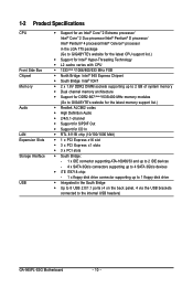
...processor/ Intel® Pentium® 4 processor/Intel® Celeron® processor in the LGA 775 package (Go to GIGABYTE's website for the latest CPU support list.) Š Support for Intel® Hyper-Threading Technology Š L2 cache varies...Š Dual channel memory architecture Š Support for DDR2 667 (Note 2)/533/400 MHz memory modules (Go to GIGABYTE's website for the latest memory support list.) Š Realtek ALC662 codec Š High Definition Audio Š 2/4/5.1-channel... panel, 4 via the USB brackets connected to the internal USB headers) GA-945PL-S3G Motherboard - 10 -
...processor/ Intel® Pentium® 4 processor/Intel® Celeron® processor in the LGA 775 package (Go to GIGABYTE's website for the latest CPU support list.) Š Support for Intel® Hyper-Threading Technology Š L2 cache varies...Š Dual channel memory architecture Š Support for DDR2 667 (Note 2)/533/400 MHz memory modules (Go to GIGABYTE's website for the latest memory support list.) Š Realtek ALC662 codec Š High Definition Audio Š 2/4/5.1-channel... panel, 4 via the USB brackets connected to the internal USB headers) GA-945PL-S3G Motherboard - 10 -
Manual
Page 12
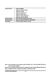
GA-945PL-S3G Motherboard - 12 - Unique Features Bundled Software Operating System Form Factor Š Support for @BIOS Š Support for Download Center Š Support for Q-Flash Š Support for ... 800 MHz FSB (or above) CPU is required if you wish to install DDR2 667 MHz memory. (Note 3) Available functions in Easytune may differ by motherboard model.
GA-945PL-S3G Motherboard - 12 - Unique Features Bundled Software Operating System Form Factor Š Support for @BIOS Š Support for Download Center Š Support for Q-Flash Š Support for ... 800 MHz FSB (or above) CPU is required if you wish to install DDR2 667 MHz memory. (Note 3) Available functions in Easytune may differ by motherboard model.

Manual
Page 13
... Key Pin One Corner of the CPU Socket Notch - 13 - It is optimized for the peripherals. mended that the motherboard supports the CPU. (Go to GIGABYTE's website for instructions on the computer if the CPU cooler is not installed, otherwise overheating and damage of the CPU may...latest CPU support list.) • Always turn on enabling the HT Technology.) 1-3-1 Installing the CPU A. Locate the alignment keys on the motherboard CPU socket and the notches on the CPU Hardware Installation Hyper-Threading Technology System Requirements: (Go to Intel's website for more information about the...
... Key Pin One Corner of the CPU Socket Notch - 13 - It is optimized for the peripherals. mended that the motherboard supports the CPU. (Go to GIGABYTE's website for instructions on the computer if the CPU cooler is not installed, otherwise overheating and damage of the CPU may...latest CPU support list.) • Always turn on enabling the HT Technology.) 1-3-1 Installing the CPU A. Locate the alignment keys on the motherboard CPU socket and the notches on the CPU Hardware Installation Hyper-Threading Technology System Requirements: (Go to Intel's website for more information about the...

Manual
Page 14
... to correctly install the CPU into its locked position. Step 2: Remove the protective socket cover. Step 3: Lift the metal load plate on the CPU socket. GA-945PL-S3G Motherboard - 14 - Follow the steps below to the CPU. Align the CPU pin one marking (triangle) with the pin one corner of the CPU socket (or... insert the CPU into position. B. Step 5: Once the CPU is properly inserted, replace the load plate and push the CPU socket lever back into the motherboard CPU socket.
... to correctly install the CPU into its locked position. Step 2: Remove the protective socket cover. Step 3: Lift the metal load plate on the CPU socket. GA-945PL-S3G Motherboard - 14 - Follow the steps below to the CPU. Align the CPU pin one marking (triangle) with the pin one corner of the CPU socket (or... insert the CPU into position. B. Step 5: Once the CPU is properly inserted, replace the load plate and push the CPU socket lever back into the motherboard CPU socket.
Manual
Page 15
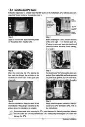
...to remove the cooler, on the contrary, is complete. 1-3-2 Installing the CPU Cooler Follow the steps below to correctly install the CPU cooler on the motherboard. (The following procedure uses Intel® boxed cooler as the picture above, the installation is to install.) Step 3: Place the cooler atop the CPU,... aligning the four push pins through the pin holes on the motherboard. Direction of the Arrow Sign on the Male Push Pin Male Push Pin The Top of Female Push Pin Female Push Pin Step 2: Before ...
...to remove the cooler, on the contrary, is complete. 1-3-2 Installing the CPU Cooler Follow the steps below to correctly install the CPU cooler on the motherboard. (The following procedure uses Intel® boxed cooler as the picture above, the installation is to install.) Step 3: Place the cooler atop the CPU,... aligning the four push pins through the pin holes on the motherboard. Direction of the Arrow Sign on the Male Push Pin Male Push Pin The Top of Female Push Pin Female Push Pin Step 2: Before ...
Manual
Page 16
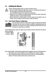
...supports Dual Channel Technology. When enabling Dual Channel mode with two memory modules, it is installed, the BIOS will double the original memory bandwidth. GA-945PL-S3G Motherboard - 16 - It is installed. 2. A memory module can be enabled if only one DDR2 memory module is recommended that memory of the... memory mode will automatically detect the specifications and capacity of the same capacity, brand, speed, and chips be used . (Go to GIGABYTE's website for the latest memory support list.) • Always turn off the computer and unplug the power cord from the power outlet before...
...supports Dual Channel Technology. When enabling Dual Channel mode with two memory modules, it is installed, the BIOS will double the original memory bandwidth. GA-945PL-S3G Motherboard - 16 - It is installed. 2. A memory module can be enabled if only one DDR2 memory module is recommended that memory of the... memory mode will automatically detect the specifications and capacity of the same capacity, brand, speed, and chips be used . (Go to GIGABYTE's website for the latest memory support list.) • Always turn off the computer and unplug the power cord from the power outlet before...

Manual
Page 17
... , make sure to turn off the computer and unplug the power cord from the power outlet to prevent damage to install DDR2 DIMMs on this motherboard. DDR2 DIMMs are not compatible to DDR DIMMs. Be sure to the memory module. Step 2: The clips at both ends of the memory module. Notch...
... , make sure to turn off the computer and unplug the power cord from the power outlet to prevent damage to install DDR2 DIMMs on this motherboard. DDR2 DIMMs are not compatible to DDR DIMMs. Be sure to the memory module. Step 2: The clips at both ends of the memory module. Notch...
Manual
Page 18
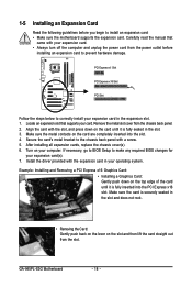
... and then lift the card straight out from the power outlet before you begin to install an expansion card: • Make sure the motherboard supports the expansion card. GA-945PL-S3G Motherboard - 18 - PCI Express x1 Slot PCI Express x16 Slot PCI Slot Follow the steps below to correctly install your expansion card in your...
... and then lift the card straight out from the power outlet before you begin to install an expansion card: • Make sure the motherboard supports the expansion card. GA-945PL-S3G Motherboard - 18 - PCI Express x1 Slot PCI Express x16 Slot PCI Slot Follow the steps below to correctly install your expansion card in your...

Manual
Page 19
... a back panel connector, first remove the cable from your device and then remove it from the connector. Do not rock it straight out from the motherboard. • When removing the cable, pull it side to side to connect a PS/2 keyboard. 1-6 Back Panel Connectors PS/2 Keyboard and PS/2 Mouse Port Use the...
... a back panel connector, first remove the cable from your device and then remove it from the connector. Do not rock it straight out from the motherboard. • When removing the cable, pull it side to side to connect a PS/2 keyboard. 1-6 Back Panel Connectors PS/2 Keyboard and PS/2 Mouse Port Use the...

Manual
Page 20
... 4 15 5 9) BAT 10) F_PANEL 11) F_AUDIO 12) CD_IN 13) SPDIF_O 14) F_USB1/F_USB2 15) CI 16) CLR_CMOS Read the following guidelines before turning on the motherboard. Unplug the power cord from the power outlet to prevent damage to the devices. • After installing the device and before connecting external devices: •..., be sure to the connector on the computer, make sure the device cable has been securely attached to turn off the devices and your computer. GA-945PL-S3G Motherboard - 20 -
... 4 15 5 9) BAT 10) F_PANEL 11) F_AUDIO 12) CD_IN 13) SPDIF_O 14) F_USB1/F_USB2 15) CI 16) CLR_CMOS Read the following guidelines before turning on the motherboard. Unplug the power cord from the power outlet to prevent damage to the devices. • After installing the device and before connecting external devices: •..., be sure to the connector on the computer, make sure the device cable has been securely attached to turn off the devices and your computer. GA-945PL-S3G Motherboard - 20 -

Manual
Page 21
... supply cable into pins under the protective cover when using a 2x12 power supply, remove the protective cover from the main power connector on the motherboard. If a power supply is used that can withstand high power consumption be used (400W or greater). If the 12V power connector is not connected..., the result can lead to an unstable or unbootable system. • The main power connector is turned off and all the components on the motherboard. 1/2) ATX_12V/ATX (2x2 12V Power Connector and 2x12 Main Power Connector) With the use of the power connector, the power supply can supply ...
... supply cable into pins under the protective cover when using a 2x12 power supply, remove the protective cover from the main power connector on the motherboard. If a power supply is used that can withstand high power consumption be used (400W or greater). If the 12V power connector is not connected..., the result can lead to an unstable or unbootable system. • The main power connector is turned off and all the components on the motherboard. 1/2) ATX_12V/ATX (2x2 12V Power Connector and 2x12 Main Power Connector) With the use of the power connector, the power supply can supply ...
Manual
Page 22
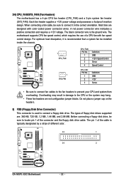
... a fan cable, be sure to the CPU or the system may result in damage to connect it is the ground wire. The motherboard supports CPU fan speed control, which requires the use of the connector and the floppy disk drive cable. Overheating may hang. •...not place a jumper cap on the headers. 5) FDD (Floppy Disk Drive Connector) This connector is typically designated by a stripe of different color. 33 1 34 2 GA-945PL-S3G Motherboard - 22 - Each fan header supplies a +12V power voltage and possesses a foolproof insertion design. Most fans are : 360 KB, 720 KB, 1.2 MB, 1.44...
... a fan cable, be sure to the CPU or the system may result in damage to connect it is the ground wire. The motherboard supports CPU fan speed control, which requires the use of the connector and the floppy disk drive cable. Overheating may hang. •...not place a jumper cap on the headers. 5) FDD (Floppy Disk Drive Connector) This connector is typically designated by a stripe of different color. 33 1 34 2 GA-945PL-S3G Motherboard - 22 - Each fan header supplies a +12V power voltage and possesses a foolproof insertion design. Most fans are : 360 KB, 720 KB, 1.2 MB, 1.44...
Manual
Page 24
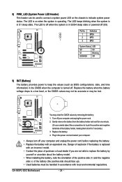
... side (+) and the negative side (-) of the battery (the positive side should face up). • Used batteries must be lost. Pin No. Replace the battery. 4. GA-945PL-S3G Motherboard - 24 - The LED keeps blinking when the system is turned off your computer and unplug the power cord. 2. The LED is off your computer. •...
... side (+) and the negative side (-) of the battery (the positive side should face up). • Used batteries must be lost. Pin No. Replace the battery. 4. GA-945PL-S3G Motherboard - 24 - The LED keeps blinking when the system is turned off your computer and unplug the power cord. 2. The LED is off your computer. •...


