Manual
Page 4
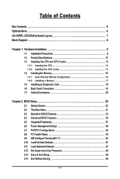
... ...6 GA-945PL-S3G Motherboard Layout 7 Block Diagram ...8 Chapter 1 Hardware Installation 9 1-1 Installation Precautions 9 1-2 Product Specifications 10 1-3 Installing the CPU and CPU Cooler 13 1-3-1 Installing the CPU 13 1-3-2 Installing the CPU Cooler 15 1-4 Installing the Memory 16 1-4-1 Dual Channel Memory Configuration 16 1-4-2 Installing a Memory 17 1-5 Installing an Expansion Card 18 1-6 Back Panel Connectors 19 1-7 Internal Connectors 20 Chapter 2 BIOS Setup 29 2-1 Startup Screen 30 2-2 The Main Menu 31 2-3 Standard CMOS Features 33 2-4 Advanced BIOS Features...
... ...6 GA-945PL-S3G Motherboard Layout 7 Block Diagram ...8 Chapter 1 Hardware Installation 9 1-1 Installation Precautions 9 1-2 Product Specifications 10 1-3 Installing the CPU and CPU Cooler 13 1-3-1 Installing the CPU 13 1-3-2 Installing the CPU Cooler 15 1-4 Installing the Memory 16 1-4-1 Dual Channel Memory Configuration 16 1-4-2 Installing a Memory 17 1-5 Installing an Expansion Card 18 1-6 Back Panel Connectors 19 1-7 Internal Connectors 20 Chapter 2 BIOS Setup 29 2-1 Startup Screen 30 2-2 The Main Menu 31 2-3 Standard CMOS Features 33 2-4 Advanced BIOS Features...
Manual
Page 10
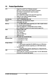
... In Š RTL 8111B chip (10/100/1000 Mbit) Š 1 x PCI Express x16 slot Š 3 x PCI Express x1 slots Š 3 x PCI slots Š South Bridge: - 1 x IDE connector supporting ATA-100/66/33 and up to 2 IDE devices - 4 x SATA 3Gb/s connectors supporting up to 4 SATA 3Gb/s devices Š iTE IT8718 chip: - 1 x floppy disk drive connector supporting up to 1 floppy disk drive Š Integrated in the South Bridge Š Up to 8 USB 2.0/1.1 ports (4 on the back panel, 4 via the USB brackets connected to the internal USB headers) GA-945PL-S3G Motherboard - 10 -
... In Š RTL 8111B chip (10/100/1000 Mbit) Š 1 x PCI Express x16 slot Š 3 x PCI Express x1 slots Š 3 x PCI slots Š South Bridge: - 1 x IDE connector supporting ATA-100/66/33 and up to 2 IDE devices - 4 x SATA 3Gb/s connectors supporting up to 4 SATA 3Gb/s devices Š iTE IT8718 chip: - 1 x floppy disk drive connector supporting up to 1 floppy disk drive Š Integrated in the South Bridge Š Up to 8 USB 2.0/1.1 ports (4 on the back panel, 4 via the USB brackets connected to the internal USB headers) GA-945PL-S3G Motherboard - 10 -
Manual
Page 16
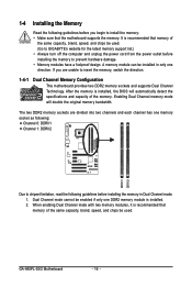
...Dual Channel mode. 1. GA-945PL-S3G Motherboard - 16 - The two DDR2 memory sockets are unable to insert the memory, switch the direction. 1-4-1 Dual Channel Memory Configuration This motherboard provides two DDR2 memory sockets and supports Dual Channel Technology. When enabling Dual Channel mode with two memory modules, it is installed. 2. After the memory is recommended that memory of the same capacity, brand, speed, and chips be used . Enabling Dual Channel memory mode will automatically detect the specifications and capacity of the memory. 1-4 Installing the Memory...
...Dual Channel mode. 1. GA-945PL-S3G Motherboard - 16 - The two DDR2 memory sockets are unable to insert the memory, switch the direction. 1-4-1 Dual Channel Memory Configuration This motherboard provides two DDR2 memory sockets and supports Dual Channel Technology. When enabling Dual Channel mode with two memory modules, it is installed. 2. After the memory is recommended that memory of the same capacity, brand, speed, and chips be used . Enabling Dual Channel memory mode will automatically detect the specifications and capacity of the memory. 1-4 Installing the Memory...
Manual
Page 18
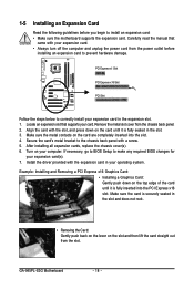
... damage. PCI Express x1 Slot PCI Express x16 Slot PCI Slot Follow the steps below to make any required BIOS changes for your card. Make sure the card is securely seated in the slot. 3. GA-945PL-S3G Motherboard - 18 - Remove the metal slot cover from the power outlet before you begin to the chassis back panel with the expansion card in the expansion slot. 1. If necessary, go to BIOS Setup to correctly install your expansion card in your...
... damage. PCI Express x1 Slot PCI Express x16 Slot PCI Slot Follow the steps below to make any required BIOS changes for your card. Make sure the card is securely seated in the slot. 3. GA-945PL-S3G Motherboard - 18 - Remove the metal slot cover from the power outlet before you begin to the chassis back panel with the expansion card in the expansion slot. 1. If necessary, go to BIOS Setup to correctly install your expansion card in your...
Manual
Page 22
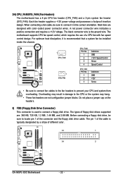
...8226; Be sure to connect fan cables to the fan headers to locate pin 1 of the connector and the floppy disk drive cable. The pin 1 of a CPU fan with color-coded power connector wires. Overheating may hang. • These fan headers are not configuration jumper blocks. 3/4) CPU_FAN/SYS_FAN (Fan Headers) The motherboard has a 4-pin CPU fan header (CPU_FAN) and a 3-pin system fan header (SYS_FAN). Each fan header supplies a +12V power voltage and possesses a foolproof insertion design. The motherboard supports CPU fan speed control, which requires the use of the cable is the ground...
...8226; Be sure to connect fan cables to the fan headers to locate pin 1 of the connector and the floppy disk drive cable. The pin 1 of a CPU fan with color-coded power connector wires. Overheating may hang. • These fan headers are not configuration jumper blocks. 3/4) CPU_FAN/SYS_FAN (Fan Headers) The motherboard has a 4-pin CPU fan header (CPU_FAN) and a 3-pin system fan header (SYS_FAN). Each fan header supplies a +12V power voltage and possesses a foolproof insertion design. The motherboard supports CPU fan speed control, which requires the use of the cable is the ground...
Manual
Page 24
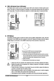
....) 3. Plug in the CMOS when the computer is turned off your computer and unplug the power cord before replacing the battery. • Replace the battery with an incorrect model. • Contact the place of purchase or local dealer if you are not able to replace the battery by removing the battery: 1. GA-945PL-S3G Motherboard - 24 - The LED keeps blinking when the system is in S3/S4 sleep state...
....) 3. Plug in the CMOS when the computer is turned off your computer and unplug the power cord before replacing the battery. • Replace the battery with an incorrect model. • Contact the place of purchase or local dealer if you are not able to replace the battery by removing the battery: 1. GA-945PL-S3G Motherboard - 24 - The LED keeps blinking when the system is in S3/S4 sleep state...
Manual
Page 26
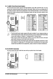
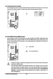
... Panel Audio: 2 10 Pin No. You may connect the audio cable that has different wire assignments, please contact the chassis manufacturer. 12) CD_IN (CD In Connector) You may connect your optical drive to this header. For information about connecting the front panel audio module that came with your chassis front panel audio module to the header. 1 Pin No. Definition 1 CD-L 2 GND 3 GND 4 CD-R GA-945PL-S3G Motherboard - 26 - 11) F_AUDIO (Front Panel Audio Header) The front panel audio header supports Intel High...
... Panel Audio: 2 10 Pin No. You may connect the audio cable that has different wire assignments, please contact the chassis manufacturer. 12) CD_IN (CD In Connector) You may connect your optical drive to this header. For information about connecting the front panel audio module that came with your chassis front panel audio module to the header. 1 Pin No. Definition 1 CD-L 2 GND 3 GND 4 CD-R GA-945PL-S3G Motherboard - 26 - 11) F_AUDIO (Front Panel Audio Header) The front panel audio header supports Intel High...
Manual
Page 28
... BIOS configurations). GA-945PL-S3G Motherboard - 28 - Open: Normal Short: Clear CMOS Values • Always turn off your computer and unplug the power cord from the power outlet before clearing the CMOS values. • After clearing the CMOS values and before turning on the two pins to temporarily short the two pins or use a metal object like a screwdriver to remove the jumper cap from the jumper. date information and BIOS configurations) and reset the CMOS values to Chapter 2, "BIOS Setup...
... BIOS configurations). GA-945PL-S3G Motherboard - 28 - Open: Normal Short: Clear CMOS Values • Always turn off your computer and unplug the power cord from the power outlet before clearing the CMOS values. • After clearing the CMOS values and before turning on the two pins to temporarily short the two pins or use a metal object like a screwdriver to remove the jumper cap from the jumper. date information and BIOS configurations) and reset the CMOS values to Chapter 2, "BIOS Setup...
Manual
Page 29
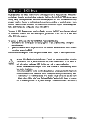
... Power-On Self-Test (POST) during the POST. To upgrade the BIOS, use either the GIGABYTE Q-Flash or @BIOS utility. • Q-Flash allows the user to quickly and easily upgrade or back up BIOS without entering the operating system. • @BIOS is recommended that you need to) to the "Load Optimized Defaults" section in this chapter or introductions of the battery/clearing CMOS jumper in the main menu of the BIOS Setup program. For instructions on . Inadequate BIOS flashing...
... Power-On Self-Test (POST) during the POST. To upgrade the BIOS, use either the GIGABYTE Q-Flash or @BIOS utility. • Q-Flash allows the user to quickly and easily upgrade or back up BIOS without entering the operating system. • @BIOS is recommended that you need to) to the "Load Optimized Defaults" section in this chapter or introductions of the battery/clearing CMOS jumper in the main menu of the BIOS Setup program. For instructions on . Inadequate BIOS flashing...
Manual
Page 30
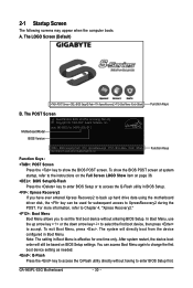
... first boot device, then press to enter BIOS Setup first. The system will still be used for 945PL-S3G D11 . . . . : BIOS Setup/Q-Flash : XpressRecovery2 : Boot Menu : Qflash 09/10/2007-945-ICH7-6A89TG03C-00 Function Keys Function Keys: : POST Screen Press the key to show the BIOS POST screen at system startup, refer to the instructions on the Full Screen LOGO Show item on BIOS Setup settings. Note: The setting in Boot Menu. Motherboard Model BIOS Version Intel 945 BIOS for subsequent access to access the Q-Flash utility...
... first boot device, then press to enter BIOS Setup first. The system will still be used for 945PL-S3G D11 . . . . : BIOS Setup/Q-Flash : XpressRecovery2 : Boot Menu : Qflash 09/10/2007-945-ICH7-6A89TG03C-00 Function Keys Function Keys: : POST Screen Press the key to show the BIOS POST screen at system startup, refer to the instructions on the Full Screen LOGO Show item on BIOS Setup settings. Note: The setting in Boot Menu. Motherboard Model BIOS Version Intel 945 BIOS for subsequent access to access the Q-Flash utility...
Manual
Page 32
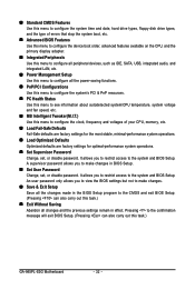
... configure the device boot order, advanced features available on the CPU, and the primary display adapter. „ Integrated Peripherals Use this menu to configure all peripheral devices, such as IDE, SATA, USB, integrated audio, and integrated LAN, etc. „ Power Management Setup Use this menu to configure all changes and the previous settings remain in BIOS Setup. „ Set User Password Change, set , or disable password. Pressing to the confirmation message will exit BIOS Setup. (Pressing can also carry out this task.) GA-945PL-S3G Motherboard...
... configure the device boot order, advanced features available on the CPU, and the primary display adapter. „ Integrated Peripherals Use this menu to configure all peripheral devices, such as IDE, SATA, USB, integrated audio, and integrated LAN, etc. „ Power Management Setup Use this menu to configure all changes and the previous settings remain in BIOS Setup. „ Set User Password Change, set , or disable password. Pressing to the confirmation message will exit BIOS Setup. (Pressing can also carry out this task.) GA-945PL-S3G Motherboard...
Manual
Page 33
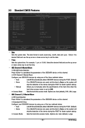
...; Manual skip the detection of the device during the POST. (Default) If no IDE/SATA devices are used , set the date. Select the desired field and use the up arrow or down arrow key to set this channel. IDE Channel 0 Master/Slave IDE HDD Auto-Detection Press to CHS. Options are : Auto (default), Large. - 33 - Time Sets the system time. Access Mode Sets the hard drive access mode. BIOS Setup Sets the hard drive access mode. is week (read-only), month, date and year. Options are : Auto (default), CHS...
...; Manual skip the detection of the device during the POST. (Default) If no IDE/SATA devices are used , set the date. Select the desired field and use the up arrow or down arrow key to set this channel. IDE Channel 0 Master/Slave IDE HDD Auto-Detection Press to CHS. Options are : Auto (default), Large. - 33 - Time Sets the system time. Access Mode Sets the hard drive access mode. BIOS Setup Sets the hard drive access mode. is week (read-only), month, date and year. Options are : Auto (default), CHS...
Manual
Page 35
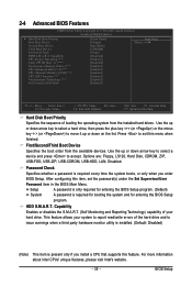
... your hard drive. After configuring this feature. Options are: Floppy, LS120, Hard Disk, CDROM, ZIP, USB-FDD, USB-ZIP, USB-CDROM, USB-HDD, LAN, Disabled. Capability CPU Hyper-Threading (Note) Limit CPUID Max. Password Check Specifies whether a password is required for booting the system and for entering the BIOS Setup program. (Default) System A password is required every time the system boots, or only when you install a CPU that supports this item, set the password(s) under the Set Supervisor/User Password item in the BIOS Main Menu.
... your hard drive. After configuring this feature. Options are: Floppy, LS120, Hard Disk, CDROM, ZIP, USB-FDD, USB-ZIP, USB-CDROM, USB-HDD, LAN, Disabled. Capability CPU Hyper-Threading (Note) Limit CPUID Max. Password Check Specifies whether a password is required for booting the system and for entering the BIOS Setup program. (Default) System A password is required every time the system boots, or only when you install a CPU that supports this item, set the password(s) under the Set Supervisor/User Password item in the BIOS Main Menu.
Manual
Page 36
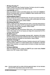
... Windows XP operating system; GA-945PL-S3G Motherboard - 36 - For more information about Intel CPUs' unique features, please visit Intel's website. Set this feature. When enabled, the CPU core frequency and voltage will allow a platform to limit CPUID maximum value. Virtualization enhanced by Intel® Virtualization Technology will be reduced when the CPU is present only if you install a CPU that support multi-processors mode. (Default: Enabled) Limit CPUID Max. This feature only works...
... Windows XP operating system; GA-945PL-S3G Motherboard - 36 - For more information about Intel CPUs' unique features, please visit Intel's website. Set this feature. When enabled, the CPU core frequency and voltage will allow a platform to limit CPUID maximum value. Virtualization enhanced by Intel® Virtualization Technology will be reduced when the CPU is present only if you install a CPU that support multi-processors mode. (Default: Enabled) Limit CPUID Max. This feature only works...
Manual
Page 37
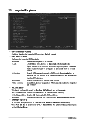
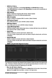
... Mode is set SATA devices to Combined. BIOS Setup Disabled Disables the integrated SATA controller. Auto Lets BIOS set to Combined or Enhanced mode. Non-Combined Sets all SATA devices to operate in SATA mode. Ch.0 Master/Slave Sets the IDE channels to Ch. 0 Master/Slave. (Default) Ch.1 Master/Slave Sets the IDE channels to USB Controller USB 2.0 Controller USB Keyboard Support USB Mouse Support Legacy USB storage detect Azalia Codec Onboard H/W LAN ` SMART LAN Onboard LAN Boot ROM Onboard Serial Port 1 Onboard Parallel Port Parallel Port Mode x ECP Mode Use DMA [Enabled...
... Mode is set SATA devices to Combined. BIOS Setup Disabled Disables the integrated SATA controller. Auto Lets BIOS set to Combined or Enhanced mode. Non-Combined Sets all SATA devices to operate in SATA mode. Ch.0 Master/Slave Sets the IDE channels to Ch. 0 Master/Slave. (Default) Ch.1 Master/Slave Sets the IDE channels to USB Controller USB 2.0 Controller USB Keyboard Support USB Mouse Support Legacy USB storage detect Azalia Codec Onboard H/W LAN ` SMART LAN Onboard LAN Boot ROM Onboard Serial Port 1 Onboard Parallel Port Parallel Port Mode x ECP Mode Use DMA [Enabled...
Manual
Page 38
.... GA-945PL-S3G Motherboard - 38 - SMART LAN (LAN Cable Diagnostic Function) CMOS Setup Utility-Copyright (C) 1984-2007 Award Software SMART LAN Start detecting at Port..... Refer to settings. USB Controller Enables or disables the integrated USB controller. (Default: Enabled) Disabled will show Open and the Length fields show 0.0m, as shown in audio card instead of the attached LAN cable. USB 2.0 Controller Enables or disables the integrated USB 2.0 controller. (Default: Enabled) USB Keyboard Support Allows USB keyboard to be used in MS-DOS. (Default: Disabled) USB Mouse Support...
.... GA-945PL-S3G Motherboard - 38 - SMART LAN (LAN Cable Diagnostic Function) CMOS Setup Utility-Copyright (C) 1984-2007 Award Software SMART LAN Start detecting at Port..... Refer to settings. USB Controller Enables or disables the integrated USB controller. (Default: Enabled) Disabled will show Open and the Length fields show 0.0m, as shown in audio card instead of the attached LAN cable. USB 2.0 Controller Enables or disables the integrated USB 2.0 controller. (Default: Enabled) USB Keyboard Support Allows USB keyboard to be used in MS-DOS. (Default: Disabled) USB Mouse Support...

Manual
Page 39
... item is configurable only if Parallel Port Mode is activated. Options are not used in a 10/100 Mbps environment, so their Status fields will show Short and thenlength shown will only operate at about 1.6m on the LAN cable connected to activate the boot ROM integrated with the onboard LAN chip. (Default: Disabled) Onboard Serial Port 1 Enables or disables the first serial port and specifies its base I /O address and corresponding interrupt. Onboard LAN Boot ROM Allows you...
... item is configurable only if Parallel Port Mode is activated. Options are not used in a 10/100 Mbps environment, so their Status fields will show Short and thenlength shown will only operate at about 1.6m on the LAN cable connected to activate the boot ROM integrated with the onboard LAN chip. (Default: Disabled) Onboard Serial Port 1 Enables or disables the first serial port and specifies its base I /O address and corresponding interrupt. Onboard LAN Boot ROM Allows you...
Manual
Page 44
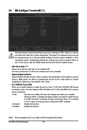
... installed CPU. Robust Graphics Booster Robust Graphics Booster (R.G.B.) helps to enable the use of a FSB 1333 CoreTM 2 processor through overclocking. O.C. Or press any key to alter the clock ratio for advanced users only and we recommend you to continue the POST. (Default) Disables this feature. The item is present only if a CPU with DDR2 533 (or above) memory module(s). Auto Sets this occurs, clear the CMOS values and reset the board to default...
... installed CPU. Robust Graphics Booster Robust Graphics Booster (R.G.B.) helps to enable the use of a FSB 1333 CoreTM 2 processor through overclocking. O.C. Or press any key to alter the clock ratio for advanced users only and we recommend you to continue the POST. (Default) Disables this feature. The item is present only if a CPU with DDR2 533 (or above) memory module(s). Auto Sets this occurs, clear the CMOS values and reset the board to default...

Manual
Page 49
... the key. BIOS Setup This saves the changes to the BIOS Setup Main Menu. - 49 - Press or to return to the CMOS and exits the BIOS Setup program. Press or to return to the BIOS Setup Main Menu. 2-14 Exit Without Saving CMOS Setup Utility-Copyright (C) 1984-2007 Award Software ` Standard CMOS Features Load Fail-Safe Defaults ` Advanced BIOS Features Load Optimized Defaults ` Integrated Peripherals Set Supervisor Password ` Power Management Setup Quit Without Saving (SYe/tNU)?seNr Password ` PnP/PCI Configurations Save & Exit Setup ` PC...
... the key. BIOS Setup This saves the changes to the BIOS Setup Main Menu. - 49 - Press or to return to the CMOS and exits the BIOS Setup program. Press or to return to the BIOS Setup Main Menu. 2-14 Exit Without Saving CMOS Setup Utility-Copyright (C) 1984-2007 Award Software ` Standard CMOS Features Load Fail-Safe Defaults ` Advanced BIOS Features Load Optimized Defaults ` Integrated Peripherals Set Supervisor Password ` Power Management Setup Quit Without Saving (SYe/tNU)?seNr Password ` PnP/PCI Configurations Save & Exit Setup ` PC...
Manual
Page 75
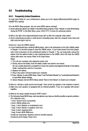
... computer. 5. A: Some advanced options are some BIOS options missing? Replace the battery. 4. A: The following Award BIOS beep code descriptions may help you identify possible computer problems. (For reference only.) 1 short: System boots successfully 2 short: CMOS setting error 1 long, 1 short: Memory or motherboard error 1 long, 2 short: Monitor or graphics card error 1 long, 3 short: Keyboard error 1 long, 9 short: BIOS ROM error Continuous long beeps: Graphics card not inserted properly Continuous short beeps: Power error - 75 - 5-2 Troubleshooting 5-2-1 Frequently Asked Questions To...
... computer. 5. A: Some advanced options are some BIOS options missing? Replace the battery. 4. A: The following Award BIOS beep code descriptions may help you identify possible computer problems. (For reference only.) 1 short: System boots successfully 2 short: CMOS setting error 1 long, 1 short: Memory or motherboard error 1 long, 2 short: Monitor or graphics card error 1 long, 3 short: Keyboard error 1 long, 9 short: BIOS ROM error Continuous long beeps: Graphics card not inserted properly Continuous short beeps: Power error - 75 - 5-2 Troubleshooting 5-2-1 Frequently Asked Questions To...


