
User Manual
Page 1
... golden finger is compatible with 2X(3.3V) / 4X(1.5V) mode AGP slot, but they support 2X(3.3V) only. The GA-8KNXP / GA-8IK1100 (or any AGP Pro 4X/8X only) motherboards might not function properly, If you install this card in it . Example 2: Some ATi Rage 128 Pro graphics cards made ... with 2X/4X mode AGP slot. Note : Although Gigabyte's AG32S(G) graphics card is based on ATi Rage 128 Pro chip, the design of AG32S(G) is compliance with Intel® 845(GE/PE) / 845(E/G) / 850(E) / E7205 / 865(G/PE/P) / 875P based motherboards. Before you install PCI cards, please remove the Dual...
... golden finger is compatible with 2X(3.3V) / 4X(1.5V) mode AGP slot, but they support 2X(3.3V) only. The GA-8KNXP / GA-8IK1100 (or any AGP Pro 4X/8X only) motherboards might not function properly, If you install this card in it . Example 2: Some ATi Rage 128 Pro graphics cards made ... with 2X/4X mode AGP slot. Note : Although Gigabyte's AG32S(G) graphics card is based on ATi Rage 128 Pro chip, the design of AG32S(G) is compliance with Intel® 845(GE/PE) / 845(E/G) / 850(E) / E7205 / 865(G/PE/P) / 875P based motherboards. Before you install PCI cards, please remove the Dual...

User Manual
Page 2
Third-party brands and names are the property of this motherboard. Due to update the information contained herein. The author assumes no responsibility for any labels on motherboard, this may appear in this document nor does the author make a commitment to rapid change in technology, some of the specifications might be out of date before publication of this booklet. Please do not remove any errors or omissions that may void the warranty of their respective owners.
Third-party brands and names are the property of this motherboard. Due to update the information contained herein. The author assumes no responsibility for any labels on motherboard, this may appear in this document nor does the author make a commitment to rapid change in technology, some of the specifications might be out of date before publication of this booklet. Please do not remove any errors or omissions that may void the warranty of their respective owners.

User Manual
Page 4
... the following two conditions: (1) This device may not cause harmful and (2) this device must accept any inference received, including that the product Product Name: Motherboard Model Number: GA-8KNXP / GA-8IK1100 Conforms to the following specifications: FCC Part 15, Subpart B, Section 15.107(a) and Section 15.109(a), Class B Digital Device Supplementary Information: This device...
... the following two conditions: (1) This device may not cause harmful and (2) this device must accept any inference received, including that the product Product Name: Motherboard Model Number: GA-8KNXP / GA-8IK1100 Conforms to the following specifications: FCC Part 15, Subpart B, Section 15.107(a) and Section 15.109(a), Class B Digital Device Supplementary Information: This device...

User Manual
Page 5
GA-8KNXP / GA-8IK1100 P4 Titan Series Motherboard USER'S MANUAL Pentium® 4 Processor Motherboard Rev. 1002 12ME-8KNXP-1002
GA-8KNXP / GA-8IK1100 P4 Titan Series Motherboard USER'S MANUAL Pentium® 4 Processor Motherboard Rev. 1002 12ME-8KNXP-1002

User Manual
Page 6
English Table of Content Warning 4 Chapter 1 Introduction 5 Features Summary 5 GA-8KNXP / GA-8IK1100 Motherboard Layout 8 Block Diagram 9 Chapter 2 Hardware Installation Process 11 Step 1: Install the Central Processing Unit (CPU 12 Step 1-1: CPU Installation 12 Step 1-2: CPU Cooling Fan Installation ... Main Menu (For example: BIOS Ver. : E4 40 Standard CMOS Features 42 Advanced BIOS Features 45 Integrated Peripherals 47 Power Management Setup 53 * Only for GA-8KNXP. GA-8KNXP / GA-8IK1100 Motherboard - 2 -
English Table of Content Warning 4 Chapter 1 Introduction 5 Features Summary 5 GA-8KNXP / GA-8IK1100 Motherboard Layout 8 Block Diagram 9 Chapter 2 Hardware Installation Process 11 Step 1: Install the Central Processing Unit (CPU 12 Step 1-1: CPU Installation 12 Step 1-2: CPU Cooling Fan Installation ... Main Menu (For example: BIOS Ver. : E4 40 Standard CMOS Features 42 Advanced BIOS Features 45 Integrated Peripherals 47 Power Management Setup 53 * Only for GA-8KNXP. GA-8KNXP / GA-8IK1100 Motherboard - 2 -

User Manual
Page 8
... the bottom portion of your computer. 1. GA-8KNXP / GA-8IK1100 Motherboard - 4 - Hold components by the hole. Installing the motherboard to the base without worrying about short circuits. In this way you work on the motherboard. English Warning Computer motherboards and expansion cards contain very delicate Integrated Circuit... on the base and there are separated from the system. 5. Just cut off before handling computer components. If the motherboard has mounting holes, but they don't line up with the components whenever the components are no slots to the mounting holes...
... the bottom portion of your computer. 1. GA-8KNXP / GA-8IK1100 Motherboard - 4 - Hold components by the hole. Installing the motherboard to the base without worrying about short circuits. In this way you work on the motherboard. English Warning Computer motherboards and expansion cards contain very delicate Integrated Circuit... on the base and there are separated from the system. 5. Just cut off before handling computer components. If the motherboard has mounting holes, but they don't line up with the components whenever the components are no slots to the mounting holes...

User Manual
Page 9
... support DDR333 and DDR266 memory module. English Chapter 1 Introduction Features Summary Form Factor Motherboard CPU Chipset Memory I/O Control Slots On-Board IDE Serial ATA y 30.5cm x 24.4cm ATX size form factor, 6 layers PCB y GA-8KNXP or GA-8IK1100 y Socket 478 for GA-8KNXP. - 5 - Due to be continued...... A FSB 533 Pentium 4 processor will only support...
... support DDR333 and DDR266 memory module. English Chapter 1 Introduction Features Summary Form Factor Motherboard CPU Chipset Memory I/O Control Slots On-Board IDE Serial ATA y 30.5cm x 24.4cm ATX size form factor, 6 layers PCB y GA-8KNXP or GA-8IK1100 y Socket 478 for GA-8KNXP. - 5 - Due to be continued...... A FSB 533 Pentium 4 processor will only support...

User Manual
Page 10
GA-8KNXP / GA-8IK1100 Motherboard - 6 - to 2 SATA devices y ACPI and ATA/ATAPI6 y Only supports Windows XP # Only for GA-8IK1100. English On-Board Peripherals Hardware Monitor On-Board LAN On-Board Sound On-Board IDE RAID* On-Board SATA RAID * Only for HDD y Supports IDE ... data striping (RAID 0) or mirroring (RAID 1) or striping+mirroring (RAID 0+RAID 1) y Supports JBOD function y Supports concurrent dual ATA133 IDE controller operation y Support ATAPI mode for GA-8KNXP.
GA-8KNXP / GA-8IK1100 Motherboard - 6 - to 2 SATA devices y ACPI and ATA/ATAPI6 y Only supports Windows XP # Only for GA-8IK1100. English On-Board Peripherals Hardware Monitor On-Board LAN On-Board Sound On-Board IDE RAID* On-Board SATA RAID * Only for HDD y Supports IDE ... data striping (RAID 0) or mirroring (RAID 1) or striping+mirroring (RAID 0+RAID 1) y Supports JBOD function y Supports concurrent dual ATA133 IDE controller operation y Support ATAPI mode for GA-8KNXP.

User Manual
Page 12
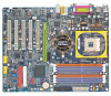
English GA-8KNXP / GA-8IK1100 Motherboard Layout KB_MS R_USB CPU_FAN RAM_LED COMA SOCKET 478 ATX FDD VRM_CONN* LPT GA-8KNXP (or GA-8IK1100) DDR1 DDR2 DDR3 DDR4 DDR5 DDR6 IDE2 ATX_12V NB_FAN COMB LAN USB F_AUDIO CD_IN AUDIO1 SPDIF_IO Intel® 875P Intel KENAI II* Intel Kinnereth ...SIL3112* SATA1_SII* SATA1_SB TSB43AB23 IDE4* F2_1394 IT8712F WOL P4 Titan IR_CIR GAME SYS_FAN PCI5 IDE3* BACKUP MAIN BIOS BIOS F_USB1 F1_1394 F_USB2 * Only for GA-8KNXP. # Only for GA-8IK1100. INFO_LINK PWR_LED F_PANEL CLR_PWD IDE1 PWR_FAN GA-8KNXP / GA-8IK1100 Motherboard - 8 -
English GA-8KNXP / GA-8IK1100 Motherboard Layout KB_MS R_USB CPU_FAN RAM_LED COMA SOCKET 478 ATX FDD VRM_CONN* LPT GA-8KNXP (or GA-8IK1100) DDR1 DDR2 DDR3 DDR4 DDR5 DDR6 IDE2 ATX_12V NB_FAN COMB LAN USB F_AUDIO CD_IN AUDIO1 SPDIF_IO Intel® 875P Intel KENAI II* Intel Kinnereth ...SIL3112* SATA1_SII* SATA1_SB TSB43AB23 IDE4* F2_1394 IT8712F WOL P4 Titan IR_CIR GAME SYS_FAN PCI5 IDE3* BACKUP MAIN BIOS BIOS F_USB1 F1_1394 F_USB2 * Only for GA-8KNXP. # Only for GA-8IK1100. INFO_LINK PWR_LED F_PANEL CLR_PWD IDE1 PWR_FAN GA-8KNXP / GA-8IK1100 Motherboard - 8 -

User Manual
Page 14
English GA-8KNXP / GA-8IK1100 Motherboard - 10 -
English GA-8KNXP / GA-8IK1100 Motherboard - 10 -

User Manual
Page 16
... into the socket. - 12 - Please make sure the CPU type is supported by the motherboard. 2. If you do not match the CPU socket Pin 1 and CPU cut edge on the CPU upper corner. CPU Top View GA-8KNXP / GA-8IK1100 Motherboard 4. Please change the insert orientation. Angling the rod to 65-degree maybe feel a kind...
... into the socket. - 12 - Please make sure the CPU type is supported by the motherboard. 2. If you do not match the CPU socket Pin 1 and CPU cut edge on the CPU upper corner. CPU Top View GA-8KNXP / GA-8IK1100 Motherboard 4. Please change the insert orientation. Angling the rod to 65-degree maybe feel a kind...

User Manual
Page 17
Fasten the cooling fan supportingbase onto the CPU socket on the motherboard. 2. Make sure the CPU fan is plugged in to CPU cooling fan user's manual for more detail installation procedure. 1. English Step 1-2: CPU Cooling Fan Installation ...
Fasten the cooling fan supportingbase onto the CPU socket on the motherboard. 2. Make sure the CPU fan is plugged in to CPU cooling fan user's manual for more detail installation procedure. 1. English Step 1-2: CPU Cooling Fan Installation ...

User Manual
Page 18
When DIMM LED is ON, do not install / remove DIMM from socket. 2. Please change the insert orientation. The motherboard has 6 dual inline memory module (DIMM) sockets. Memory size can only fit in one direction due to the one direction. 2. The DIMM socket has a ...The DIMM module can only fit in one direction due to remove the DIMM module. Insert the DIMM memory module vertically into the DIMM socket. GA-8KNXP / GA-8IK1100 Motherboard - 14 - Wrong orientation will automatically detects memory type and size. Close the plastic clip at both edges of the DIMM sockets to the following...
When DIMM LED is ON, do not install / remove DIMM from socket. 2. Please change the insert orientation. The motherboard has 6 dual inline memory module (DIMM) sockets. Memory size can only fit in one direction due to the one direction. 2. The DIMM socket has a ...The DIMM module can only fit in one direction due to remove the DIMM module. Insert the DIMM memory module vertically into the DIMM socket. GA-8KNXP / GA-8IK1100 Motherboard - 14 - Wrong orientation will automatically detects memory type and size. Close the plastic clip at both edges of the DIMM sockets to the following...

User Manual
Page 20
...: Single Side) 1 memory module 2 memory modules 3 memory modules DIMM 1 DS/SS X X DS/SS DS/SS DIMM 3 X DS/SS X DS/SS SS DIMM5 X X DS/SS X SS GA-8KNXP / GA-8IK1100 Motherboard - 16 - English 5.
...: Single Side) 1 memory module 2 memory modules 3 memory modules DIMM 1 DS/SS X X DS/SS DS/SS DIMM 3 X DS/SS X DS/SS SS DIMM5 X X DS/SS X SS GA-8KNXP / GA-8IK1100 Motherboard - 16 - English 5.
User Manual
Page 21
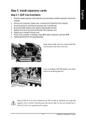
.... 7. Hardware Installation Process Power on the card are installing a AGP PRO graphic card, please remove the protecting plate first. If you are indeed seated in motherboard. 4. Replace your computer's chassis cover, screws and slot bracket from the operating system. Be sure the metal contacts on the computer, if necessary, setup BIOS...
.... 7. Hardware Installation Process Power on the card are installing a AGP PRO graphic card, please remove the protecting plate first. If you are indeed seated in motherboard. 4. Replace your computer's chassis cover, screws and slot bracket from the operating system. Be sure the metal contacts on the computer, if necessary, setup BIOS...

User Manual
Page 22
...2. The DPS2connector has a notch, so the DPS2 can only fit in a Dual Power System: • Parallel Mode : DPS2 and motherboard CPU power can work simultaneously, providing a total of 6-phase power circuit. Insert the DPS2 vertically into the socket and then push it down... to remove the DPS2. * Only for the new generation Intel® platform. Reverse the installation steps if you the Dual Power System function. GA-8KNXP / GA-8IK1100 Motherboard - 18 - English Step 3-2: DPS2 (Dual Power System 2) Installation* What is a daughter card which can provide you want to install a DPS2...
...2. The DPS2connector has a notch, so the DPS2 can only fit in a Dual Power System: • Parallel Mode : DPS2 and motherboard CPU power can work simultaneously, providing a total of 6-phase power circuit. Insert the DPS2 vertically into the socket and then push it down... to remove the DPS2. * Only for the new generation Intel® platform. Reverse the installation steps if you the Dual Power System function. GA-8KNXP / GA-8IK1100 Motherboard - 18 - English Step 3-2: DPS2 (Dual Power System 2) Installation* What is a daughter card which can provide you want to install a DPS2...
User Manual
Page 24
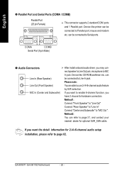
can be connected to Parallel port; If you want the detail information for hardware connection. GA-8KNXP / GA-8IK1100 Motherboard - 20 - Device like printer can be connected to Line-In jack. Method1: Connect "Front Speaker" to "Line Out" Connect "Rear Speaker" to "Line In" Connect "...
can be connected to Parallel port; If you want the detail information for hardware connection. GA-8KNXP / GA-8IK1100 Motherboard - 20 - Device like printer can be connected to Line-In jack. Method1: Connect "Front Speaker" to "Line Out" Connect "Rear Speaker" to "Line In" Connect "...

User Manual
Page 26
... 11 3.3V 12 -12V 13 GND 20 10 14 PS_ON(soft on/off) 15 GND 16 GND 17 GND 18 -5V 19 VCC 20 VCC GA-8KNXP / GA-8IK1100 Motherboard - 22 - Pin No. Pin No. English 1) ATX_12V (+12V Power Connector) This connector (ATX_12V) supplies the CPU operation voltage (Vcore).
... 11 3.3V 12 -12V 13 GND 20 10 14 PS_ON(soft on/off) 15 GND 16 GND 17 GND 18 -5V 19 VCC 20 VCC GA-8KNXP / GA-8IK1100 Motherboard - 22 - Pin No. Pin No. English 1) ATX_12V (+12V Power Connector) This connector (ATX_12V) supplies the CPU operation voltage (Vcore).

User Manual
Page 28
Definition 1 VCC 2 GND GA-8KNXP / GA-8IK1100 Motherboard - 24 - Sometimes will not work. English 5) PWR_FAN (Power Fan Connector) This connector allows you installed wrong direction, the chip fan will damage the chip fan. (Usually black cable is GND) 1 Pin No. Definition 1 GND 2 +12V 3 Sense 6) NB_FAN (Chip Fan Connector) If you to link with the cooling fan on the system case to lower the system temperature. 1 Pin No.
Definition 1 VCC 2 GND GA-8KNXP / GA-8IK1100 Motherboard - 24 - Sometimes will not work. English 5) PWR_FAN (Power Fan Connector) This connector allows you installed wrong direction, the chip fan will damage the chip fan. (Usually black cable is GND) 1 Pin No. Definition 1 GND 2 +12V 3 Sense 6) NB_FAN (Chip Fan Connector) If you to link with the cooling fan on the system case to lower the system temperature. 1 Pin No.

User Manual
Page 30
If you high speed transfer rates (150MB/sec). Then, install the correct driver to this connector, it in unity with BIOS (either RAID or ATA133). GA-8KNXP / GA-8IK1100 Motherboard - 26 - English 9) IDE3 / IDE4 (RAID/ATA133, Green Connector) * Important Notice: The red stripe of the ribbon cable must be the same side with WinXP. 7 1 SATA0_SB...
If you high speed transfer rates (150MB/sec). Then, install the correct driver to this connector, it in unity with BIOS (either RAID or ATA133). GA-8KNXP / GA-8IK1100 Motherboard - 26 - English 9) IDE3 / IDE4 (RAID/ATA133, Green Connector) * Important Notice: The red stripe of the ribbon cable must be the same side with WinXP. 7 1 SATA0_SB...


