Manual
Page 4
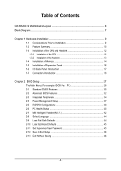
Table of Contents GA-8I925X-G Motherboard Layout 6 Block Diagram ...7 Chapter 1 Hardware Installation 9 1-1 Considerations Prior to Installation 9 1-2 Feature Summary 10 1-3 Installation of the CPU and Heatsink 12 1-3-1 Installation of the CPU 12 1-3-2 Installation of the Heatsink 13 1-4 Installation of Memory 14 1-5 Installation of Expansion Cards 16 1-6 I/O Back Panel Introduction 17 1-7 Connectors Introduction 18 Chapter 2 BIOS Setup...
Table of Contents GA-8I925X-G Motherboard Layout 6 Block Diagram ...7 Chapter 1 Hardware Installation 9 1-1 Considerations Prior to Installation 9 1-2 Feature Summary 10 1-3 Installation of the CPU and Heatsink 12 1-3-1 Installation of the CPU 12 1-3-2 Installation of the Heatsink 13 1-4 Installation of Memory 14 1-5 Installation of Expansion Cards 16 1-6 I/O Back Panel Introduction 17 1-7 Connectors Introduction 18 Chapter 2 BIOS Setup...
Manual
Page 9
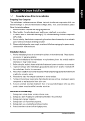
...is switched off the computer and unplug its components. 5. Prior to wear an electrostatic discharge (ESD) cuff when handling electronic components (CPU, RAM). 4. Before using the product, please verify that you are no leftover screws or metal components placed on the motherboard or ... as well as a result of electrostatic discharge (ESD). Prior to installing the electronic components, please have a problem related to be an unofficial Gigabyte product. - 9 - Turning on the motherboard. Damage due to use of an antistatic pad or within the computer casing. 6. Damage due to...
...is switched off the computer and unplug its components. 5. Prior to wear an electrostatic discharge (ESD) cuff when handling electronic components (CPU, RAM). 4. Before using the product, please verify that you are no leftover screws or metal components placed on the motherboard or ... as well as a result of electrostatic discharge (ESD). Prior to installing the electronic components, please have a problem related to be an unofficial Gigabyte product. - 9 - Turning on the motherboard. Damage due to use of an antistatic pad or within the computer casing. 6. Damage due to...
Manual
Page 10
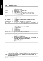
... of memory is reserved for system usage and therefore the actual memory size is less than the stated amount. Center/Subwoofer Speaker Out ; GA-8I925X-G Motherboard - 10 - Side Speaker Out connection Š SPDIF In/Out connection Š CD In connection (Note 1) Due to 4GB...138; Supports Jack Sensing function Š Supports 2 / 4 / 6 / 8 channel audio Š Supports Line In ; MIC ; English 1-2 Feature Summary CPU Chipset Memory Slots IDE Connections FDD Connections Onboard SATA Peripherals Onboard LAN Onboard Audio Š Supports the latest Intel® Pentium® 4 LGA775...
... of memory is reserved for system usage and therefore the actual memory size is less than the stated amount. Center/Subwoofer Speaker Out ; GA-8I925X-G Motherboard - 10 - Side Speaker Out connection Š SPDIF In/Out connection Š CD In connection (Note 1) Due to 4GB...138; Supports Jack Sensing function Š Supports 2 / 4 / 6 / 8 channel audio Š Supports Line In ; MIC ; English 1-2 Feature Summary CPU Chipset Memory Slots IDE Connections FDD Connections Onboard SATA Peripherals Onboard LAN Onboard Audio Š Supports the latest Intel® Pentium® 4 LGA775...
Manual
Page 11
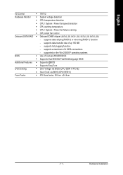
... English I/O Control Š IT8712 Hardware Monitor Š System voltage detection Š CPU temperature detection Š CPU / System / Power fan speed detection Š CPU warning temperature Š CPU / System / Power fan failure warning Š CPU smart fan control Onboard SATA RAID Š Onboard ICH6R chipset (SATA0_SB, SATA1_SB, SATA2_SB,... Additional Features Š Supports @BIOS Š Supports EasyTune Overclocking Š Over Voltage via BIOS (CPU/ DDR II/ PCI-E) Š Over Clock via BIOS (CPU/ DDR II) Form Factor Š ATX form factor; 30.5cm x 24.4cm - 11 -
... English I/O Control Š IT8712 Hardware Monitor Š System voltage detection Š CPU temperature detection Š CPU / System / Power fan speed detection Š CPU warning temperature Š CPU / System / Power fan failure warning Š CPU smart fan control Onboard SATA RAID Š Onboard ICH6R chipset (SATA0_SB, SATA1_SB, SATA2_SB,... Additional Features Š Supports @BIOS Š Supports EasyTune Overclocking Š Over Voltage via BIOS (CPU/ DDR II/ PCI-E) Š Over Clock via BIOS (CPU/ DDR II) Form Factor Š ATX form factor; 30.5cm x 24.4cm - 11 -
Manual
Page 12
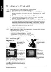
...overheating and permanent damage of the CPU may occur. 5. BIOS: A BIOS that the system bus frequency be set beyond the proper specifications, please do so according to the CPU during installation.) GA-8I925X-G Motherboard - 12 - Align the indented corner of the CPU with HT Technology - Please take... note of the one indented corner of the CPU. 3. Please add an even layer of heat sink ...
...overheating and permanent damage of the CPU may occur. 5. BIOS: A BIOS that the system bus frequency be set beyond the proper specifications, please do so according to the CPU during installation.) GA-8I925X-G Motherboard - 12 - Align the indented corner of the CPU with HT Technology - Please take... note of the one indented corner of the CPU. 3. Please add an even layer of heat sink ...
Manual
Page 13
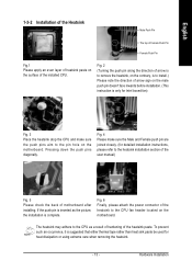
...is suggested that either thermal tape rather than heat sink paste be used for Intel boxed fan) Fig. 3 Place the heatsink atop the CPU and make sure the Male and Female push pin are joined closely. (for detailed installation instructions, please refer to the heatsink installation section...male push pin doesn't face inwards before installation. (This instruction is complete. Fig. 6 Finally, please attach the power connector of the installed CPU. English 1-3-2 Installation of the Heatsink Male Push Pin The top of Female Push Pin Female Push Pin Fig.1 Please apply an even layer of...
...is suggested that either thermal tape rather than heat sink paste be used for Intel boxed fan) Fig. 3 Place the heatsink atop the CPU and make sure the Male and Female push pin are joined closely. (for detailed installation instructions, please refer to the heatsink installation section...male push pin doesn't face inwards before installation. (This instruction is complete. Fig. 6 Finally, please attach the power connector of the installed CPU. English 1-3-2 Installation of the Heatsink Male Push Pin The top of Female Push Pin Female Push Pin Fig.1 Please apply an even layer of...
Manual
Page 19
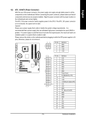
... that is able to handle the system voltage requirements. Before connecting the power connector, please make sure that can supply enough stable power to the CPU.
... that is able to handle the system voltage requirements. Before connecting the power connector, please make sure that can supply enough stable power to the CPU.
Manual
Page 20
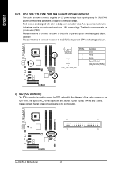
... and requires a +12V power voltage. The black connector wire is used to the FDD drive. Please remember to connect the power to the CPU fan to prevent CPU overheating and failure. 1 CPU_FAN Pin No. 1 2 3 4 1 SYS_FAN / PWR_FAN Definition GND +12V Sense Speed Control (Only for CPU_FAN... designed with color-coded power connector wires. Please remember to connect the power to the cooler to the pin1 position. 2 34 1 33 GA-8I925X-G Motherboard - 20 - Please connect the red power connector wire to prevent system overheating and failure. Most coolers are : 360KB, 720KB, 1....
... and requires a +12V power voltage. The black connector wire is used to the FDD drive. Please remember to connect the power to the CPU fan to prevent CPU overheating and failure. 1 CPU_FAN Pin No. 1 2 3 4 1 SYS_FAN / PWR_FAN Definition GND +12V Sense Speed Control (Only for CPU_FAN... designed with color-coded power connector wires. Please remember to connect the power to the cooler to the pin1 position. 2 34 1 33 GA-8I925X-G Motherboard - 20 - Please connect the red power connector wire to prevent system overheating and failure. Most coolers are : 360KB, 720KB, 1....
Manual
Page 28
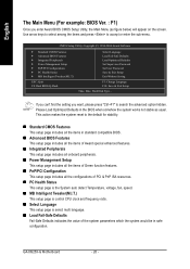
... ` Standard CMOS Features ` Advanced BIOS Features ` Integrated Peripherals ` Power Management Setup ` PnP/PCI Configurations ` PC Health Status ` MB Intelligent Tweaker(M.I .T.) This setup page is control CPU clock and frequency ratio. „ Select Language This setup page is select multi language. „ Load Fail-Safe Defaults Fail-Safe Defaults indicates the value...+F1" to search the advanced option hidden. If you can't find the setting you enter Award BIOS CMOS Setup Utility, the Main Menu (as usual. GA-8I925X-G Motherboard - 28 -
... ` Standard CMOS Features ` Advanced BIOS Features ` Integrated Peripherals ` Power Management Setup ` PnP/PCI Configurations ` PC Health Status ` MB Intelligent Tweaker(M.I .T.) This setup page is control CPU clock and frequency ratio. „ Select Language This setup page is select multi language. „ Load Fail-Safe Defaults Fail-Safe Defaults indicates the value...+F1" to search the advanced option hidden. If you can't find the setting you enter Award BIOS CMOS Setup Utility, the Main Menu (as usual. GA-8I925X-G Motherboard - 28 -
Manual
Page 31
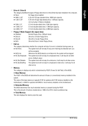
...; BIOS Setup Both Drive A & B are 3 mode Floppy Drives. it will determine the amount of floppy disk drive A or drive B that has been installed in the CPU's memory address map. it will stop for all other errors. (Default value) All, But Diskette The system boot will stop for all other errors. it...
...; BIOS Setup Both Drive A & B are 3 mode Floppy Drives. it will determine the amount of floppy disk drive A or drive B that has been installed in the CPU's memory address map. it will stop for all other errors. (Default value) All, But Diskette The system boot will stop for all other errors. it...

Manual
Page 32
...your boot device priority by CDROM. USB-FDD Select your boot device priority by LAN. CDROM Select your boot device priority by USB-CDROM. GA-8I925X-G Motherboard - 32 - ZIP Select your boot device priority by USB-FDD. USB-CDROM Select your boot device priority by USB-HDD. ...(C) 1984-2004 Award Software Advanced BIOS Features ` Hard Disk Boot Priority First Boot Device Second Boot Device Third Boot Device Password Check # CPU Hyper-Threading Limit CPUID Max. Press to Setup page if the correct password is not entered at the prompt. (Default value) The system...
...your boot device priority by CDROM. USB-FDD Select your boot device priority by LAN. CDROM Select your boot device priority by USB-CDROM. GA-8I925X-G Motherboard - 32 - ZIP Select your boot device priority by USB-FDD. USB-CDROM Select your boot device priority by USB-HDD. ...(C) 1984-2004 Award Software Advanced BIOS Features ` Hard Disk Boot Priority First Boot Device Second Boot Device Third Boot Device Password Check # CPU Hyper-Threading Limit CPUID Max. Press to Setup page if the correct password is not entered at the prompt. (Default value) The system...
Manual
Page 33
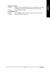
Please note that this feature is only working Disabled for windows XP. - 33 - BIOS Setup English CPU Hyper-Threading Enabled Enables CPU Hyper Threading Feature. to 3 Enabled Disabled Limit CPUID Maximum value to 3 when use older OS like NT4. (Default value) Disables CPUID Limit for operating system with multi processors mode supported. (Default value) Disables CPU Hyper Threading. Limit CPUID Max.
Please note that this feature is only working Disabled for windows XP. - 33 - BIOS Setup English CPU Hyper-Threading Enabled Enables CPU Hyper Threading Feature. to 3 Enabled Disabled Limit CPUID Maximum value to 3 when use older OS like NT4. (Default value) Disables CPUID Limit for operating system with multi processors mode supported. (Default value) Disables CPU Hyper Threading. Limit CPUID Max.
Manual
Page 40
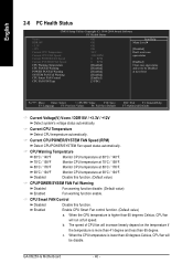
... / +3.3V / +12V Detect system's voltage status automatically. GA-8I925X-G Motherboard - 40 - English 2-6 PC Health Status CMOS Setup Utility-Copyright (C) 1984-2004 Award Software PC Health Status Vcore DDR18V +3.3V +12V Current CPU Temperature Current CPU FAN Speed Current POWER FAN Speed Current SYSTEM FAN Speed CPU Warning Temperature CPU FAN Fail Warning POWER FAN Fail Warning...
... / +3.3V / +12V Detect system's voltage status automatically. GA-8I925X-G Motherboard - 40 - English 2-6 PC Health Status CMOS Setup Utility-Copyright (C) 1984-2004 Award Software PC Health Status Vcore DDR18V +3.3V +12V Current CPU Temperature Current CPU FAN Speed Current POWER FAN Speed Current SYSTEM FAN Speed CPU Warning Temperature CPU FAN Fail Warning POWER FAN Fail Warning...
Manual
Page 41
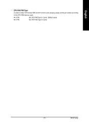
English CPU FAN PIN Type In order to make "CPU Smart FAN Control" function work properly, please set the pin number according to the CPU FAN that you used. 3 PIN Set CPU FAN Type to 3 pins. (Default value) 4 PIN Set CPU FAN Type to 4 pins. - 41 - BIOS Setup
English CPU FAN PIN Type In order to make "CPU Smart FAN Control" function work properly, please set the pin number according to the CPU FAN that you used. 3 PIN Set CPU FAN Type to 3 pins. (Default value) 4 PIN Set CPU FAN Type to 4 pins. - 41 - BIOS Setup
Manual
Page 42
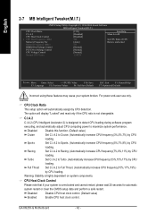
...%) by CPU loading. Disabled Disable CPU host clock control. (Default value) Enabled Enable CPU host clock control. C.I.A.2 C.I .A.2 to maximize system performance. Disabled Disable this function. (Default value) Cruise Set C.I .A.2 (CPU Intelligent Acelerator 2) is designed to detect CPU loading during software program executing, and automatically adjust CPU computing power to Cruise. (Automatically increase CPU frequency(3%,5%,7%) by CPU detection. GA-8I925X-G Motherboard...
...%) by CPU loading. Disabled Disable CPU host clock control. (Default value) Enabled Enable CPU host clock control. C.I.A.2 C.I .A.2 to maximize system performance. Disabled Disable this function. (Default value) Cruise Set C.I .A.2 (CPU Intelligent Acelerator 2) is designed to detect CPU loading during software program executing, and automatically adjust CPU computing power to Cruise. (Automatically increase CPU frequency(3%,5%,7%) by CPU detection. GA-8I925X-G Motherboard...
Manual
Page 43
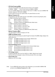
... Set DIMM OverVoltage Control to +0.2V. For power End-User use an 800MHz FSB processor, please set to Enabled. 100MHz ~ 355MHz Set CPU Host Clock from 0.8375V to +0.1V. Set DIMM OverVoltage Control to +0.1V. for FSB(Front Side Bus) frequency=800MHz, 2.00 Memory ...Host clock x 3. 4 Memory Frequency = Host clock x 4. BIOS Setup Set DIMM OverVoltage Control to overcome wrong frequency issue. Normal CPU Vcore Display your CPU vcore voltage. (Note) To use a 533MHz FSB processor, please set Memory Frequency For to the memory may cause your system through...
... Set DIMM OverVoltage Control to +0.2V. For power End-User use an 800MHz FSB processor, please set to Enabled. 100MHz ~ 355MHz Set CPU Host Clock from 0.8375V to +0.1V. Set DIMM OverVoltage Control to +0.1V. for FSB(Front Side Bus) frequency=800MHz, 2.00 Memory ...Host clock x 3. 4 Memory Frequency = Host clock x 4. BIOS Setup Set DIMM OverVoltage Control to overcome wrong frequency issue. Normal CPU Vcore Display your CPU vcore voltage. (Note) To use a 533MHz FSB processor, please set Memory Frequency For to the memory may cause your system through...
Manual
Page 51
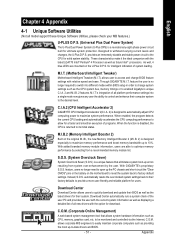
.... S.O.S. (System Overclock Saver) System Overclock Saver (S.O.S.) is returned to withstand varying current levels and changes, the U-Plus D.P.S. C.I.A.2 (CPU Intelligent Accelerator 2) GIGABYTE CPU Intelligent Accelerator 2(C.I .B. 2 features. automatically resets the overclocked system settings back to their system. Through GIGABYTE M.I .B.2 (Memory Intelligent Booster 2) Built on the U-Plus D.P.S. M.I .T. to 10%. English Chapter 4 Appendix 4-1 Unique Software Utilities (Not all...
.... S.O.S. (System Overclock Saver) System Overclock Saver (S.O.S.) is returned to withstand varying current levels and changes, the U-Plus D.P.S. C.I.A.2 (CPU Intelligent Accelerator 2) GIGABYTE CPU Intelligent Accelerator 2(C.I .B. 2 features. automatically resets the overclocked system settings back to their system. Through GIGABYTE M.I .B.2 (Memory Intelligent Booster 2) Built on the U-Plus D.P.S. M.I .T. to 10%. English Chapter 4 Appendix 4-1 Unique Software Utilities (Not all...


