Manual
Page 1
GA-8I915PC Duo Intel® Pentium® 4 LGA775 Processor Motherboard User's Manual Rev. 1001 12ME-8I915PCD-1001
GA-8I915PC Duo Intel® Pentium® 4 LGA775 Processor Motherboard User's Manual Rev. 1001 12ME-8I915PCD-1001

Manual
Page 2
Motherboard GA-8I915PC Duo Jan. 21, 2005 Motherboard GA-8I915PC Duo Jan. 21, 2005
Motherboard GA-8I915PC Duo Jan. 21, 2005 Motherboard GA-8I915PC Duo Jan. 21, 2005
Manual
Page 4
Table of Contents GA-8I915PC Duo Motherboard Layout 6 Block Diagram ...7 Chapter 1 Hardware Installation 9 1-1 Considerations Prior to Installation 9 1-2 Feature Summary 10 1-3 Installation of the CPU and Heatsink 12 1-3-1 Installation of the CPU 12 1-3-2 ...
Table of Contents GA-8I915PC Duo Motherboard Layout 6 Block Diagram ...7 Chapter 1 Hardware Installation 9 1-1 Considerations Prior to Installation 9 1-2 Feature Summary 10 1-3 Installation of the CPU and Heatsink 12 1-3-1 Installation of the CPU 12 1-3-2 ...
Manual
Page 6
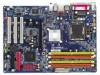
GA-8I915PC Duo Motherboard Layout KB_MS ATX_12V LGA775 CPU_FAN COMA LPT LAN COMB GA-8I915PC Duo ATX R_USB USB DDRII1 DDR1 DDRII2 DDR2 AUDIO1 AUDIO2 IT8712 F_AUDIO Intel 915P PCIE_16 Marvell 8001 CODEC CD_IN PCIE_1 PCIE_2 BIOS IR SPDIF_IO CI SATA3 ICH6 SATA2 SATA1 PCI1 SATA0 SYS_FAN CLR_CMOS IDE1 PCI2 PCI3 F_USB1 FDD BAT F_USB2 PWR_LED F_PANEL - 6 -
GA-8I915PC Duo Motherboard Layout KB_MS ATX_12V LGA775 CPU_FAN COMA LPT LAN COMB GA-8I915PC Duo ATX R_USB USB DDRII1 DDR1 DDRII2 DDR2 AUDIO1 AUDIO2 IT8712 F_AUDIO Intel 915P PCIE_16 Marvell 8001 CODEC CD_IN PCIE_1 PCIE_2 BIOS IR SPDIF_IO CI SATA3 ICH6 SATA2 SATA1 PCI1 SATA0 SYS_FAN CLR_CMOS IDE1 PCI2 PCI3 F_USB1 FDD BAT F_USB2 PWR_LED F_PANEL - 6 -
Manual
Page 7
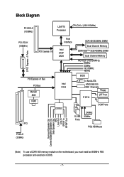
... Center/Subwoofer Speaker Out Side Speaker Out MIC Line-Out Line-In SPDIF In SPDIF Out (Note) To use a DDRII 600 memory module on the motherboard, you must install an 800MHz FSB processor and overclock in BIOS. - 7 -
... Center/Subwoofer Speaker Out Side Speaker Out MIC Line-Out Line-In SPDIF In SPDIF Out (Note) To use a DDRII 600 memory module on the motherboard, you must install an 800MHz FSB processor and overclock in BIOS. - 7 -

Manual
Page 9
... an electrostatic discharge (ESD) cuff when handling electronic components (CPU, RAM). 4. Hardware Installation Damage as a result of the motherboard or any hardware, please first carefully read the information in the provided manual. 3. Product determined to natural disaster, accident or ...pad or within the computer casing. 6. Damage due to be an unofficial Gigabyte product. - 9 - Please turn off before unplugging the power supply connector from the motherboard. To prevent damage to the motherboard, please do not remove the stickers on an uneven surface. 7. English...
... an electrostatic discharge (ESD) cuff when handling electronic components (CPU, RAM). 4. Hardware Installation Damage as a result of the motherboard or any hardware, please first carefully read the information in the provided manual. 3. Product determined to natural disaster, accident or ...pad or within the computer casing. 6. Damage due to be an unofficial Gigabyte product. - 9 - Please turn off before unplugging the power supply connector from the motherboard. To prevent damage to the motherboard, please do not remove the stickers on an uneven surface. 7. English...

Manual
Page 10
...; 1 PS/2 mouse port Š Onboard Marvell 8001 chip (10/100/1000 Mbit) Š 1 RJ 45 port (Note) To use a DDRII 600 memory module on the motherboard, you must install an 800MHz FSB processor and overclock in BIOS. GA-8I915PC Duo Motherboard - 10 -
...; 1 PS/2 mouse port Š Onboard Marvell 8001 chip (10/100/1000 Mbit) Š 1 RJ 45 port (Note) To use a DDRII 600 memory module on the motherboard, you must install an 800MHz FSB processor and overclock in BIOS. GA-8I915PC Duo Motherboard - 10 -
Manual
Page 12
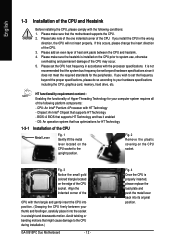
...An operation system that the system bus frequency be set beyond the proper specifications, please do so according to the CPU during installation.) GA-8I915PC Duo Motherboard - 12 - Please add an even layer of the CPU and Heatsink Before installing the CPU, please comply with the triangle and ...gently insert the CPU into the socket in a straight and downwards motion. BIOS: A BIOS that the motherboard supports the CPU. 2. Please make sure that supports HT Technology and has it into position. (Grasping the CPU firmly between the CPU and...
...An operation system that the system bus frequency be set beyond the proper specifications, please do so according to the CPU during installation.) GA-8I915PC Duo Motherboard - 12 - Please add an even layer of the CPU and Heatsink Before installing the CPU, please comply with the triangle and ...gently insert the CPU into the socket in a straight and downwards motion. BIOS: A BIOS that the motherboard supports the CPU. 2. Please make sure that supports HT Technology and has it into position. (Grasping the CPU firmly between the CPU and...
Manual
Page 13
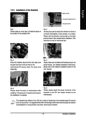
...heatsink, on the contrary, is to install.) Please note the direction of arrow sign on the motherboard.Pressing down the push pins diagonally. If the push pin is inserted as a result of hardening...Pin Female Push Pin Fig.1 Please apply an even layer of heatsink paste on the motherboard. Fig. 4 Please make sure the push pins aim to the heatsink installation section of the user manual...) Fig. 5 Please check the back of motherboard after installing. Fig. 6 Finally, please attach the power connector of the installed CPU. The ...
...heatsink, on the contrary, is to install.) Please note the direction of arrow sign on the motherboard.Pressing down the push pins diagonally. If the push pin is inserted as a result of hardening...Pin Female Push Pin Fig.1 Please apply an even layer of heatsink paste on the motherboard. Fig. 4 Please make sure the push pins aim to the heatsink installation section of the user manual...) Fig. 5 Please check the back of motherboard after installing. Fig. 6 Finally, please attach the power connector of the installed CPU. The ...

Manual
Page 14
...the memory used can be used. 2. Then push it down. Memory modules are unable to insert the module, please switch the direction. GA-8I915PC Duo Motherboard - 14 - English 1-4 Installation of the DIMM sockets to lock the DIMM module. Insert the DIMM memory module vertically into the DIMM socket...wish to remove the DIMM module. Before installing or removing memory modules, please make sure that the computer power is supported by the motherboard. Fig.2 Close the plastic clip at both edges of Memory Before installing the memory modules, please comply with each slot. A memory...
...the memory used can be used. 2. Then push it down. Memory modules are unable to insert the module, please switch the direction. GA-8I915PC Duo Motherboard - 14 - English 1-4 Installation of the DIMM sockets to lock the DIMM module. Insert the DIMM memory module vertically into the DIMM socket...wish to remove the DIMM module. Before installing or removing memory modules, please make sure that the computer power is supported by the motherboard. Fig.2 Close the plastic clip at both edges of Memory Before installing the memory modules, please comply with each slot. A memory...
Manual
Page 16
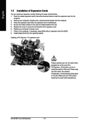
...the expansion card into expansion slot in the slot. 5. Replace the screw to secure the slot bracket of expansion card from BIOS. 8. GA-8I915PC Duo Motherboard - 16 - Remove your computer's chassis cover. 7. Replace your computer's chassis cover, screws and slot bracket from the operating system. ... contacts on the computer, if necessary, setup BIOS utility of the expansion card. 6. Power on the card are indeed seated in motherboard. 4. Installing a PCI Express x 16 expansion card: Please carefully pull out the small whitedrawable bar at the end of Expansion Cards...
...the expansion card into expansion slot in the slot. 5. Replace the screw to secure the slot bracket of expansion card from BIOS. 8. GA-8I915PC Duo Motherboard - 16 - Remove your computer's chassis cover. 7. Replace your computer's chassis cover, screws and slot bracket from the operating system. ... contacts on the computer, if necessary, setup BIOS utility of the expansion card. 6. Power on the card are indeed seated in motherboard. 4. Installing a PCI Express x 16 expansion card: Please carefully pull out the small whitedrawable bar at the end of Expansion Cards...
Manual
Page 18
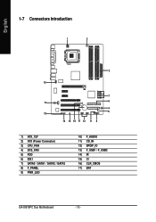
English 1-7 Connectors Introduction 1 3 2 10 7 11 6 4 5 12 14 15 16 17 13 9 8 1) ATX_12V 2) ATX (Power Connector) 3) CPU_FAN 4) SYS_FAN 5) FDD 6) IDE1 7) SATA0 / SATA1 / SATA2 / SATA3 8) F_PANEL 9) PWR_LED 10) F_AUDIO 11) CD_IN 12) SPDIF_IO 13) F_USB1 / F_USB2 14) IR 15) CI 16) CLR_CMOS 17) BAT GA-8I915PC Duo Motherboard - 18 -
English 1-7 Connectors Introduction 1 3 2 10 7 11 6 4 5 12 14 15 16 17 13 9 8 1) ATX_12V 2) ATX (Power Connector) 3) CPU_FAN 4) SYS_FAN 5) FDD 6) IDE1 7) SATA0 / SATA1 / SATA2 / SATA3 8) F_PANEL 9) PWR_LED 10) F_AUDIO 11) CD_IN 12) SPDIF_IO 13) F_USB1 / F_USB2 14) IR 15) CI 16) CLR_CMOS 17) BAT GA-8I915PC Duo Motherboard - 18 -
Manual
Page 19
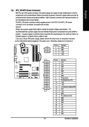
... - Please use a 24-pin ATX power supply, please remove the small cover on the power connector on the motherboard and connect tightly. Align the power connector with its proper location on the motherboard before plugging in the power cord ; The ATX_12V power connector mainly supplies power to the CPU. If you use... a power supply that can lead to an unstable system or a system that all the components on the motherboard. Definition 1 GND 3 4 2 GND 1 2 3 +12V 4 +12V Pin No. It is not connected, the system will not start .
... - Please use a 24-pin ATX power supply, please remove the small cover on the power connector on the motherboard and connect tightly. Align the power connector with its proper location on the motherboard before plugging in the power cord ; The ATX_12V power connector mainly supplies power to the CPU. If you use... a power supply that can lead to an unstable system or a system that all the components on the motherboard. Definition 1 GND 3 4 2 GND 1 2 3 +12V 4 +12V Pin No. It is not connected, the system will not start .
Manual
Page 20
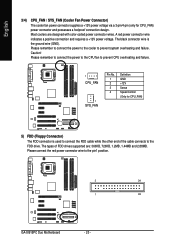
... red power connector wire to prevent system overheating and failure. Please remember to connect the power to the cooler to the pin1 position. 2 34 1 33 GA-8I915PC Duo Motherboard - 20 - English 3/4) CPU_FAN / SYS_FAN (Cooler Fan Power Connector) The cooler fan power connector supplies a +12V power voltage via a 3-pin/4-pin (only for CPU_FAN) 5) FDD (Floppy...
... red power connector wire to prevent system overheating and failure. Please remember to connect the power to the cooler to the pin1 position. 2 34 1 33 GA-8I915PC Duo Motherboard - 20 - English 3/4) CPU_FAN / SYS_FAN (Cooler Fan Power Connector) The cooler fan power connector supplies a +12V power voltage via a 3-pin/4-pin (only for CPU_FAN) 5) FDD (Floppy...

Manual
Page 22
... HD+ HD- Pin 3: NC Pin 4: Data(-) Open: Normal Close: Reset Hardware System Open: Normal Close: Power On/Off Pin 1: LED anode(+) Pin 2: LED cathode(-) NC GA-8I915PC Duo Motherboard - 22 - RESRES+ NC Reset Switch IDE Hard Disk Active LED HD (IDE Hard Disk Active LED) (Blue) SPEAK (Speaker Connector) (Amber) RES (Reset Switch) (Green...
... HD+ HD- Pin 3: NC Pin 4: Data(-) Open: Normal Close: Reset Hardware System Open: Normal Close: Power On/Off Pin 1: LED anode(+) Pin 2: LED cathode(-) NC GA-8I915PC Duo Motherboard - 22 - RESRES+ NC Reset Switch IDE Hard Disk Active LED HD (IDE Hard Disk Active LED) (Blue) SPEAK (Speaker Connector) (Amber) RES (Reset Switch) (Green...
Manual
Page 24
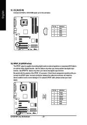
... Digital Decoder. Pin No. Use SPDIF IN feature only when your local dealer. 26 15 Pin No. 1 2 3 4 5 6 Definition Power No Pin SPDIF SPDIFI GND GND GA-8I915PC Duo Motherboard - 24 - Check the pin assignment carefully while you connect the SPDIF cable, incorrect connection between the cable and connector will make the device unable to...
... Digital Decoder. Pin No. Use SPDIF IN feature only when your local dealer. 26 15 Pin No. 1 2 3 4 5 6 Definition Power No Pin SPDIF SPDIFI GND GND GA-8I915PC Duo Motherboard - 24 - Check the pin assignment carefully while you connect the SPDIF cable, incorrect connection between the cable and connector will make the device unable to...
Manual
Page 26
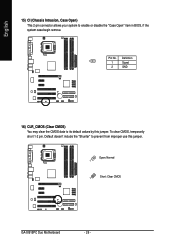
Definition 1 1 Signal 2 GND 16) CLR_CMOS (Clear CMOS) You may clear the CMOS data to prevent from improper use this jumper. Open: Normal 1 1 Short: Clear CMOS GA-8I915PC Duo Motherboard - 26 - To clear CMOS, temporarily short 1-2 pin. Default doesn't include the "Shunter" to its default values by this jumper. Pin No. English 15) CI (Chassis Intrusion, Case Open) This 2-pin connector allows your system to enable or disable the "Case Open" item in BIOS, if the system case begin remove.
Definition 1 1 Signal 2 GND 16) CLR_CMOS (Clear CMOS) You may clear the CMOS data to prevent from improper use this jumper. Open: Normal 1 1 Short: Clear CMOS GA-8I915PC Duo Motherboard - 26 - To clear CMOS, temporarily short 1-2 pin. Default doesn't include the "Shunter" to its default values by this jumper. Pin No. English 15) CI (Chassis Intrusion, Case Open) This 2-pin connector allows your system to enable or disable the "Case Open" item in BIOS, if the system case begin remove.

Manual
Page 29
... Help Restore the previous CMOS value from CMOS, only for the highlighted item. Quit and not save the current BIOS to a new BIOS, either Gigabyte's Q-Flash or @BIOS utility can enter the BIOS setup screen by pressing "Ctrl + F1". BIOS Setup Exit current page and return to use...Load the file-safe default CMOS value from the Internet. To exit the Help Window press . - 29 - When the power is turned on the motherboard supplies the necessary power to activate certain system features. English Chapter 2 BIOS Setup BIOS (Basic Input and Output System) includes a CMOS SETUP utility ...
... Help Restore the previous CMOS value from CMOS, only for the highlighted item. Quit and not save the current BIOS to a new BIOS, either Gigabyte's Q-Flash or @BIOS utility can enter the BIOS setup screen by pressing "Ctrl + F1". BIOS Setup Exit current page and return to use...Load the file-safe default CMOS value from the Internet. To exit the Help Window press . - 29 - When the power is turned on the motherboard supplies the necessary power to activate certain system features. English Chapter 2 BIOS Setup BIOS (Basic Input and Output System) includes a CMOS SETUP utility ...
Manual
Page 30
GA-8I915PC Duo Motherboard - 30 - Please Load Optimized Defaults in the BIOS when somehow the system works not stable as figure below) will appear on the screen. CMOS Setup ...
GA-8I915PC Duo Motherboard - 30 - Please Load Optimized Defaults in the BIOS when somehow the system works not stable as figure below) will appear on the screen. CMOS Setup ...
Manual
Page 32
... . Drive A / Drive B The category identifies the types of three methods: Auto Allows BIOS to automatically detect IDE devices during POST(default) None Select this information. GA-8I915PC Duo Motherboard - 32 - You can use one of floppy disk drive A or drive B that has been installed in the computer.
... . Drive A / Drive B The category identifies the types of three methods: Auto Allows BIOS to automatically detect IDE devices during POST(default) None Select this information. GA-8I915PC Duo Motherboard - 32 - You can use one of floppy disk drive A or drive B that has been installed in the computer.


