Manual
Page 4
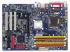
... Contents GA-8I915PC Duo Motherboard Layout 6 Block Diagram ...7 Chapter 1 Hardware Installation 9 1-1 Considerations Prior to Installation 9 1-2 Feature Summary 10 1-3 Installation of the CPU and Heatsink 12 1-3-1 Installation of the CPU 12 1-3-2 Installation of the Heatsink 13 1-4 Installation of Memory 14 1-5 Installation of Expansion Cards 16 1-6 I/O Back Panel Introduction 17 1-7 Connectors Introduction 18 Chapter 2 BIOS Setup 29 The Main Menu (For example: BIOS Ver. : D2 30 2-1 Standard CMOS Features 31 2-2 Advanced BIOS Features 34 2-3 Integrated Peripherals 36 2-4 Power...
... Contents GA-8I915PC Duo Motherboard Layout 6 Block Diagram ...7 Chapter 1 Hardware Installation 9 1-1 Considerations Prior to Installation 9 1-2 Feature Summary 10 1-3 Installation of the CPU and Heatsink 12 1-3-1 Installation of the CPU 12 1-3-2 Installation of the Heatsink 13 1-4 Installation of Memory 14 1-5 Installation of Expansion Cards 16 1-6 I/O Back Panel Introduction 17 1-7 Connectors Introduction 18 Chapter 2 BIOS Setup 29 The Main Menu (For example: BIOS Ver. : D2 30 2-1 Standard CMOS Features 31 2-2 Advanced BIOS Features 34 2-3 Integrated Peripherals 36 2-4 Power...
Manual
Page 11
... function Š Supports 2 / 4 / 6 / 8 channel audio Š Supports Line In ; Side Speaker Out connection Š Supports SPDIF In/Out connection Š CD In Š IT8712 Š System voltage detection Š CPU temperature detection Š CPU / System fan speed detection Š CPU warning temperature Š CPU / System fan failure warning Š CPU smart fan control Š Use of licensed AWARD BIOS Š Supports Q-Flash Š Supports @BIOS Š Supports EasyTune 5 Š Over Voltage via BIOS (CPU/DDR/PCI-E/FSB) Š Over Clock via BIOS (CPU/DDR/PCIE) Š ATX form factor...
... function Š Supports 2 / 4 / 6 / 8 channel audio Š Supports Line In ; Side Speaker Out connection Š Supports SPDIF In/Out connection Š CD In Š IT8712 Š System voltage detection Š CPU temperature detection Š CPU / System fan speed detection Š CPU warning temperature Š CPU / System fan failure warning Š CPU smart fan control Š Use of licensed AWARD BIOS Š Supports Q-Flash Š Supports @BIOS Š Supports EasyTune 5 Š Over Voltage via BIOS (CPU/DDR/PCI-E/FSB) Š Over Clock via BIOS (CPU/DDR/PCIE) Š ATX form factor...
Manual
Page 12
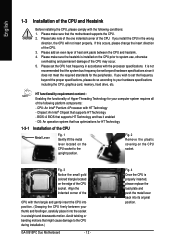
... that the system bus frequency be set the frequency beyond the proper specifications, please do so according to set beyond hardware specifications since it enabled - Please make sure the heatsink is not recommended that might cause damage to the upright position. HT functionality requirement content : Enabling the functionality of Hyper-Threading Technology for your hardware specifications including the CPU, graphics card, memory, hard drive, etc. BIOS: A BIOS that has optimizations...
... that the system bus frequency be set the frequency beyond the proper specifications, please do so according to set beyond hardware specifications since it enabled - Please make sure the heatsink is not recommended that might cause damage to the upright position. HT functionality requirement content : Enabling the functionality of Hyper-Threading Technology for your hardware specifications including the CPU, graphics card, memory, hard drive, etc. BIOS: A BIOS that has optimizations...
Manual
Page 20
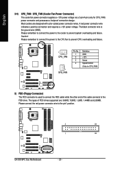
... a +12V power voltage. Please remember to connect the power to the cooler to the pin1 position. 2 34 1 33 GA-8I915PC Duo Motherboard - 20 - Most coolers are : 360KB, 720KB, 1.2MB, 1.44MB and 2.88MB. The black connector wire is used to connect the FDD cable while the other end of FDD drives supported are designed with color-coded power connector wires. The types of the cable connects to prevent CPU overheating and failure. 1 CPU_FAN 1 SYS_FAN Pin No...
... a +12V power voltage. Please remember to connect the power to the cooler to the pin1 position. 2 34 1 33 GA-8I915PC Duo Motherboard - 20 - Most coolers are : 360KB, 720KB, 1.2MB, 1.44MB and 2.88MB. The black connector wire is used to connect the FDD cable while the other end of FDD drives supported are designed with color-coded power connector wires. The types of the cable connects to prevent CPU overheating and failure. 1 CPU_FAN 1 SYS_FAN Pin No...
Manual
Page 21
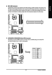
... the Serial ATA and install the proper driver in order to two IDE devices (hard drive or optical drive). Please refer to the BIOS setting for information on settings, please refer to the instructions located on the IDE device). 2 40 1 39 7) SATA0/SATA1/SATA2/SATA3 (Serial ATA Connector) Serial ATA can then connect to work properly. Pin No. English 6) IDE1 (IDE Connector) An IDE device connects to connect two IDE devices, please set the jumper on one IDE cable, and the single IDE cable can...
... the Serial ATA and install the proper driver in order to two IDE devices (hard drive or optical drive). Please refer to the BIOS setting for information on settings, please refer to the instructions located on the IDE device). 2 40 1 39 7) SATA0/SATA1/SATA2/SATA3 (Serial ATA Connector) Serial ATA can then connect to work properly. Pin No. English 6) IDE1 (IDE Connector) An IDE device connects to connect two IDE devices, please set the jumper on one IDE cable, and the single IDE cable can...

Manual
Page 22
... Pin 1: LED anode(+) Pin 2: LED cathode(-) NC GA-8I915PC Duo Motherboard - 22 - Message LED/ Power/ Sleep LED Speaker Connector Power Switch MSG+ MSG- PW+ PWSPEAK+ SPEAK- 2 20 1 19 HD+ HD- RESRES+ NC Reset Switch IDE Hard Disk Active LED HD (IDE Hard Disk Active LED) (Blue) SPEAK (Speaker Connector) (Amber) RES (Reset Switch) (Green) PW (Power Switch) (Red) MSG(Message LED/Power/Sleep LED) (Yellow) NC( Purple) Pin 1: LED anode(+) Pin 2: LED cathode(-) Pin 1: Power Pin 2- English 8) F_PANEL (Front Panel Jumper) Please connect the power LED, PC speaker, reset switch and power...
... Pin 1: LED anode(+) Pin 2: LED cathode(-) NC GA-8I915PC Duo Motherboard - 22 - Message LED/ Power/ Sleep LED Speaker Connector Power Switch MSG+ MSG- PW+ PWSPEAK+ SPEAK- 2 20 1 19 HD+ HD- RESRES+ NC Reset Switch IDE Hard Disk Active LED HD (IDE Hard Disk Active LED) (Blue) SPEAK (Speaker Connector) (Amber) RES (Reset Switch) (Green) PW (Power Switch) (Red) MSG(Message LED/Power/Sleep LED) (Yellow) NC( Purple) Pin 1: LED anode(+) Pin 2: LED cathode(-) Pin 1: Power Pin 2- English 8) F_PANEL (Front Panel Jumper) Please connect the power LED, PC speaker, reset switch and power...
Manual
Page 26
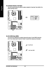
English 15) CI (Chassis Intrusion, Case Open) This 2-pin connector allows your system to its default values by this jumper. Default doesn't include the "Shunter" to prevent from improper use this jumper. Open: Normal 1 1 Short: Clear CMOS GA-8I915PC Duo Motherboard - 26 - To clear CMOS, temporarily short 1-2 pin. Pin No. Definition 1 1 Signal 2 GND 16) CLR_CMOS (Clear CMOS) You may clear the CMOS data to enable or disable the "Case Open" item in BIOS, if the system case begin remove.
English 15) CI (Chassis Intrusion, Case Open) This 2-pin connector allows your system to its default values by this jumper. Default doesn't include the "Shunter" to prevent from improper use this jumper. Open: Normal 1 1 Short: Clear CMOS GA-8I915PC Duo Motherboard - 26 - To clear CMOS, temporarily short 1-2 pin. Pin No. Definition 1 1 Signal 2 GND 16) CLR_CMOS (Clear CMOS) You may clear the CMOS data to enable or disable the "Case Open" item in BIOS, if the system case begin remove.
Manual
Page 30
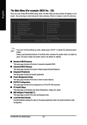
... BIOS CMOS Setup Utility, the Main Menu (as usual. GA-8I915PC Duo Motherboard - 30 - Please Load Optimized Defaults in safe configuration. CMOS Setup Utility-Copyright (C) 1984-2004 Award Software ` Standard CMOS Features ` Advanced BIOS Features ` Integrated Peripherals ` Power Management Setup ` PnP/PCI Configurations ` PC Health Status ` MB Intelligent Tweaker(M.I .T.) This setup page is the System auto detect Temperature, voltage, fan, speed. „ MB Intelligent Tweaker(M.I .T.) ESC: Quit F8: Q-Flash Load Fail-Safe Defaults Load Optimized Defaults Set Supervisor Password Set User...
... BIOS CMOS Setup Utility, the Main Menu (as usual. GA-8I915PC Duo Motherboard - 30 - Please Load Optimized Defaults in safe configuration. CMOS Setup Utility-Copyright (C) 1984-2004 Award Software ` Standard CMOS Features ` Advanced BIOS Features ` Integrated Peripherals ` Power Management Setup ` PnP/PCI Configurations ` PC Health Status ` MB Intelligent Tweaker(M.I .T.) This setup page is the System auto detect Temperature, voltage, fan, speed. „ MB Intelligent Tweaker(M.I .T.) ESC: Quit F8: Q-Flash Load Fail-Safe Defaults Load Optimized Defaults Set Supervisor Password Set User...
Manual
Page 32
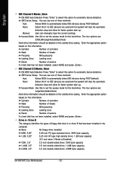
... no IDE devices are : CHS/LBA/Large/Auto(default:Auto) Hard drive information should be labeled on the outside drive casing. English IDE Channel 0 Master, Slave IDE HDD Auto-Detection Press "Enter" to select this option for automatic device detection. None No floppy drive installed 360K, 5.25" 5.25 inch PC-type standard drive; 360K byte capacity. 1.2M, 5.25" 720K, 3.5" 1.44M, 3.5" 2.88M, 3.5" 5.25 inch AT-type high-density drive; 1.2M byte capacity (3.5 inch when 3 Mode is Enabled). 3.5 inch...
... no IDE devices are : CHS/LBA/Large/Auto(default:Auto) Hard drive information should be labeled on the outside drive casing. English IDE Channel 0 Master, Slave IDE HDD Auto-Detection Press "Enter" to select this option for automatic device detection. None No floppy drive installed 360K, 5.25" 5.25 inch PC-type standard drive; 360K byte capacity. 1.2M, 5.25" 720K, 3.5" 1.44M, 3.5" 2.88M, 3.5" 5.25 inch AT-type high-density drive; 1.2M byte capacity (3.5 inch when 3 Mode is Enabled). 3.5 inch...
Manual
Page 43
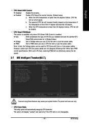
.... CPU Clock Ratio This setup option will be used for it. (Default Value) Voltage PWM Set to PWM when you use a CPU fan with 3-pin or 4-pin power cables. BIOS Setup Note: In fact, the Voltage option can be disable. Enable CPU Smart Fan control function. (Default value) a. When the CPU temperature is enabled. English CPU Smart FAN Control Disabled Enabled Disable this function. c. Set to Voltage when you use only. For power end-user use a CPU fan with a 4-pin fan power cable. CPU Smart FAN Mode This option is available only when CPU Smart FAN Control is...
.... CPU Clock Ratio This setup option will be used for it. (Default Value) Voltage PWM Set to PWM when you use a CPU fan with 3-pin or 4-pin power cables. BIOS Setup Note: In fact, the Voltage option can be disable. Enable CPU Smart Fan control function. (Default value) a. When the CPU temperature is enabled. English CPU Smart FAN Control Disabled Enabled Disable this function. c. Set to Voltage when you use only. For power end-user use a CPU fan with a 4-pin fan power cable. CPU Smart FAN Mode This option is available only when CPU Smart FAN Control is...
Manual
Page 47
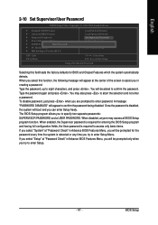
... also press to enter password. BIOS Setup English 2-10 Set Supervisor/User Password CMOS Setup Utility-Copyright (C) 1984-2004 Award Software ` Standard CMOS Features ` Advanced BIOS Features ` Integrated Peripherals ` Power Management Setup ` PnP/PCI ConfigurationEsnter Password: ` PC Health Status ` MB Intelligent Tweaker(M.I.T.) ESC: Quit F8: Q-Flash Load Fail-Safe Defaults Load Optimized Defaults Set Supervisor Password Set User Password Save & Exit Setup Exit Without Saving KLJI: Select Item F10: Save & Exit Setup Change/Set/Disable Password Selecting this function...
... also press to enter password. BIOS Setup English 2-10 Set Supervisor/User Password CMOS Setup Utility-Copyright (C) 1984-2004 Award Software ` Standard CMOS Features ` Advanced BIOS Features ` Integrated Peripherals ` Power Management Setup ` PnP/PCI ConfigurationEsnter Password: ` PC Health Status ` MB Intelligent Tweaker(M.I.T.) ESC: Quit F8: Q-Flash Load Fail-Safe Defaults Load Optimized Defaults Set Supervisor Password Set User Password Save & Exit Setup Exit Without Saving KLJI: Select Item F10: Save & Exit Setup Change/Set/Disable Password Selecting this function...
Manual
Page 49
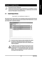
....exe. 3-1 Install Chipset Drivers After insert the driver CD, "Xpress Install" will restart your CD-ROM drive, the driver CD-title will auto start and show a question mark "?" Some device drivers will scan automatically the system and then list all the drivers that came with your motherboard into your system automatically. English Chapter 3 Install Drivers Pictures below are shown in "Universal Serial Bus controller" under Windows XP operating system, please use Windows Service Pack...
....exe. 3-1 Install Chipset Drivers After insert the driver CD, "Xpress Install" will restart your CD-ROM drive, the driver CD-title will auto start and show a question mark "?" Some device drivers will scan automatically the system and then list all the drivers that came with your motherboard into your system automatically. English Chapter 3 Install Drivers Pictures below are shown in "Universal Serial Bus controller" under Windows XP operating system, please use Windows Service Pack...
Manual
Page 53
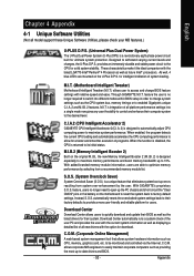
... all model support these Unique Software Utilities, please check your MB features.) U-PLUS D.P.S. (Universal Plus Dual Power System) The U-Plus Dual Power System (U-Plus DPS) is no longer need to open up -to quickly download and update their BIOS as well as the CPU system bus, memory timings or to factory default settings. feature, users no longer required to switch into a single mode now gives any user the ability to control...
... all model support these Unique Software Utilities, please check your MB features.) U-PLUS D.P.S. (Universal Plus Dual Power System) The U-Plus Dual Power System (U-Plus DPS) is no longer need to open up -to quickly download and update their BIOS as well as the CPU system bus, memory timings or to factory default settings. feature, users no longer required to switch into a single mode now gives any user the ability to control...
Manual
Page 54
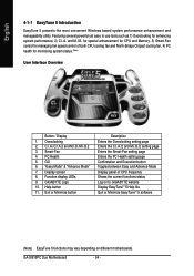
... CPU and Memory, 3) Smart-Fan control for monitoring system status.(Note) User Interface Overview Button / Display 1. PC Health 5. GA-8I915PC Duo Motherboard - 54 - C.I.A./C.I.A.2 and M.I.B./M.I .B. Help button 11. Exit or Minimize button Description Enters the Overclocking setting page Enters the C.I.A./2 and M.I .A. Display screen 8. English 4-1-1 EasyTune 5 Introduction EasyTune 5 presents the most convenient Windows based system performance enhancement and manageability utility. and M.I .B.2 3. Smart-Fan 4. Featuring several powerful yet easy to GIGABYTE website Display...
... CPU and Memory, 3) Smart-Fan control for monitoring system status.(Note) User Interface Overview Button / Display 1. PC Health 5. GA-8I915PC Duo Motherboard - 54 - C.I.A./C.I.A.2 and M.I.B./M.I .B. Help button 11. Exit or Minimize button Description Enters the Overclocking setting page Enters the C.I.A./2 and M.I .A. Display screen 8. English 4-1-1 EasyTune 5 Introduction EasyTune 5 presents the most convenient Windows based system performance enhancement and manageability utility. and M.I .B.2 3. Smart-Fan 4. Featuring several powerful yet easy to GIGABYTE website Display...

Manual
Page 59
... Enter key on your keyboard to Floppy Enter : Run :Move ESC:Reset F10:Power Off Dual BIOS utility bar Q-FlashTM utility title bar Action bar Task menu for Q-FlashTM utility Dual BIOS Utility Boot From Main Bios Main ROM Type/Size SST 49LF003A Backup ROM Type/Size SST 49LF003A 512K 512K Wide Range Protection Disable Boot From Main Bios Auto Recovery Enable Halt On Error Disable Copy Main ROM Data to Backup Load Default Settings Save Settings to CMOS Q-Flash Utility Load Main BIOS from Floppy Load Backup BIOS from Floppy Save Main BIOS to Floppy Save Backup BIOS to enable...
... Enter key on your keyboard to Floppy Enter : Run :Move ESC:Reset F10:Power Off Dual BIOS utility bar Q-FlashTM utility title bar Action bar Task menu for Q-FlashTM utility Dual BIOS Utility Boot From Main Bios Main ROM Type/Size SST 49LF003A Backup ROM Type/Size SST 49LF003A 512K 512K Wide Range Protection Disable Boot From Main Bios Auto Recovery Enable Halt On Error Disable Copy Main ROM Data to Backup Load Default Settings Save Settings to CMOS Q-Flash Utility Load Main BIOS from Floppy Load Backup BIOS from Floppy Save Main BIOS to Floppy Save Backup BIOS to enable...

Manual
Page 60
...!! Dual BIOS Utility Boot From Main Bios Main ROM Type/Size SST 49LF003A Backup ROM Type/Size SST 49LF003A 512K 512K Wide Range Protection Disable 8KNXPU.FAbuatoBRooect oF1vreofrimlye(s)MEfnoaauibnnldeBios 512K Halt On Error Disable Total size C: o1p.3y9MMain ROM DataFtroeeBsaiczkeu:p911.50K F5 : Refresh Load Default SeDttEinLg:sDelete Save Settings to CMOS Q-Flash Utility Load Main BIOS from Floppy Load Backup BIOS from Floppy Save Main BIOS to Floppy Save Backup BIOS to the floppy disk so only one BIOS file to Floppy Enter : Run :Move ESC:Reset F10:Power Off BIOS file in...
...!! Dual BIOS Utility Boot From Main Bios Main ROM Type/Size SST 49LF003A Backup ROM Type/Size SST 49LF003A 512K 512K Wide Range Protection Disable 8KNXPU.FAbuatoBRooect oF1vreofrimlye(s)MEfnoaauibnnldeBios 512K Halt On Error Disable Total size C: o1p.3y9MMain ROM DataFtroeeBsaiczkeu:p911.50K F5 : Refresh Load Default SeDttEinLg:sDelete Save Settings to CMOS Q-Flash Utility Load Main BIOS from Floppy Load Backup BIOS from Floppy Save Main BIOS to Floppy Save Backup BIOS to the floppy disk so only one BIOS file to Floppy Enter : Run :Move ESC:Reset F10:Power Off BIOS file in...
Manual
Page 61
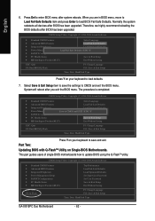
... automatically after updating. Please do not take out the floppy disk when it will be displayed. Halt On Error Disable CPolpeyasMe apirneRssOaMnyDkaetya to cBoanctkiunpue Load Default Settings Save Settings to CMOS Q-Flash Utility Load Main BIOS from Floppy Load Backup BIOS from Floppy Save Main BIOS to Floppy Save Backup BIOS to flash the backup BIOS, too. 5. Load Default Settings Save Settings to CMOS Q-Flash Utility Load Main BIOS from Floppy Load Backup BIOS from Floppy Save Main BIOS to Floppy Save Backup BIOS to Floppy Enter : Run :Move ESC:Reset F10:Power Off You...
... automatically after updating. Please do not take out the floppy disk when it will be displayed. Halt On Error Disable CPolpeyasMe apirneRssOaMnyDkaetya to cBoanctkiunpue Load Default Settings Save Settings to CMOS Q-Flash Utility Load Main BIOS from Floppy Load Backup BIOS from Floppy Save Main BIOS to Floppy Save Backup BIOS to flash the backup BIOS, too. 5. Load Default Settings Save Settings to CMOS Q-Flash Utility Load Main BIOS from Floppy Load Backup BIOS from Floppy Save Main BIOS to Floppy Save Backup BIOS to Floppy Enter : Run :Move ESC:Reset F10:Power Off You...
Manual
Page 62
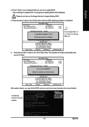
...: Dual BIOS/Q-Flash F3: Change Language F10: Save & Exit Setup Time, Date, Hard Disk Type... When you exit the BIOS menu. Press Y on your keyboard to save the settings to CMOS and exit the BIOS menu. Part Two: Updating BIOS with Q-FlashTM Utility on your keyboard to update BIOS using the Q-FlashTM utility. System will reboot after system reboots. Select Save & Exit Setup item to load BIOS Fail-Safe Defaults. GA-8I915PC Duo Motherboard - 62 - Normally the system redetects all devices after BIOS has been upgraded...
...: Dual BIOS/Q-Flash F3: Change Language F10: Save & Exit Setup Time, Date, Hard Disk Type... When you exit the BIOS menu. Press Y on your keyboard to save the settings to CMOS and exit the BIOS menu. Part Two: Updating BIOS with Q-FlashTM Utility on your keyboard to update BIOS using the Q-FlashTM utility. System will reboot after system reboots. Select Save & Exit Setup item to load BIOS Fail-Safe Defaults. GA-8I915PC Duo Motherboard - 62 - Normally the system redetects all devices after BIOS has been upgraded...
Manual
Page 73
... voltage to clear CMOS. Turn off the on . Press Del to the battery holder. 5. English 4-2 Troubleshooting Below is plugged in, so you don't need to change another speaker with an internal amplifier. To check general asked questions. Why? Please press Ctrl and F1 keys after entering BIOS menu and you will auto-detect the external VGA card after updating BIOS? Question 3: How do I disable onboard VGA card in previous BIOS after flashing BIOS. If your board has a Clear CMOS jumper...
... voltage to clear CMOS. Turn off the on . Press Del to the battery holder. 5. English 4-2 Troubleshooting Below is plugged in, so you don't need to change another speaker with an internal amplifier. To check general asked questions. Why? Please press Ctrl and F1 keys after entering BIOS menu and you will auto-detect the external VGA card after updating BIOS? Question 3: How do I disable onboard VGA card in previous BIOS after flashing BIOS. If your board has a Clear CMOS jumper...

Manual
Page 74
... use the IDE 2? gate A20 failure 7 beeps Processor exception interrupt error 8 beeps Display memory read/write failure 9 beeps ROM checksum error 10 beeps CMOS shutdown register read/write error 11 beeps Cache memory bad AWARD BIOS Beep Codes 1 short: System boots successfully 2 short: CMOS setting error 1 long 1 short: DRAM or M/B error 1 long 2 short: Monitor or display card error 1 long 3 short: Keyboard error 1 long 9 short: BIOS ROM error Continuous long beeps: DRAM error Continuous short beeps: Power error GA-8I915PC Duo Motherboard - 74 - The situations might differ from case...
... use the IDE 2? gate A20 failure 7 beeps Processor exception interrupt error 8 beeps Display memory read/write failure 9 beeps ROM checksum error 10 beeps CMOS shutdown register read/write error 11 beeps Cache memory bad AWARD BIOS Beep Codes 1 short: System boots successfully 2 short: CMOS setting error 1 long 1 short: DRAM or M/B error 1 long 2 short: Monitor or display card error 1 long 3 short: Keyboard error 1 long 9 short: BIOS ROM error Continuous long beeps: DRAM error Continuous short beeps: Power error GA-8I915PC Duo Motherboard - 74 - The situations might differ from case...


