Manual
Page 1
GA-8I915PC Duo Intel® Pentium® 4 LGA775 Processor Motherboard User's Manual Rev. 1001 12ME-8I915PCD-1001
GA-8I915PC Duo Intel® Pentium® 4 LGA775 Processor Motherboard User's Manual Rev. 1001 12ME-8I915PCD-1001

Manual
Page 2
Motherboard GA-8I915PC Duo Jan. 21, 2005 Motherboard GA-8I915PC Duo Jan. 21, 2005
Motherboard GA-8I915PC Duo Jan. 21, 2005 Motherboard GA-8I915PC Duo Jan. 21, 2005
Manual
Page 4
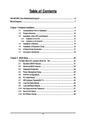
Table of Contents GA-8I915PC Duo Motherboard Layout 6 Block Diagram ...7 Chapter 1 Hardware Installation 9 1-1 Considerations Prior to Installation 9 1-2 Feature Summary 10 1-3 Installation of the CPU and Heatsink 12 1-3-1 Installation of the CPU ...
Table of Contents GA-8I915PC Duo Motherboard Layout 6 Block Diagram ...7 Chapter 1 Hardware Installation 9 1-1 Considerations Prior to Installation 9 1-2 Feature Summary 10 1-3 Installation of the CPU and Heatsink 12 1-3-1 Installation of the CPU ...
Manual
Page 6
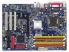
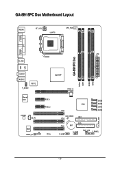
GA-8I915PC Duo Motherboard Layout KB_MS ATX_12V LGA775 CPU_FAN COMA LPT LAN COMB GA-8I915PC Duo ATX R_USB USB DDRII1 DDR1 DDRII2 DDR2 AUDIO1 AUDIO2 IT8712 F_AUDIO Intel 915P PCIE_16 Marvell 8001 CODEC CD_IN PCIE_1 PCIE_2 BIOS IR SPDIF_IO CI SATA3 ICH6 SATA2 SATA1 PCI1 SATA0 SYS_FAN CLR_CMOS IDE1 PCI2 PCI3 F_USB1 FDD BAT F_USB2 PWR_LED F_PANEL - 6 -
GA-8I915PC Duo Motherboard Layout KB_MS ATX_12V LGA775 CPU_FAN COMA LPT LAN COMB GA-8I915PC Duo ATX R_USB USB DDRII1 DDR1 DDRII2 DDR2 AUDIO1 AUDIO2 IT8712 F_AUDIO Intel 915P PCIE_16 Marvell 8001 CODEC CD_IN PCIE_1 PCIE_2 BIOS IR SPDIF_IO CI SATA3 ICH6 SATA2 SATA1 PCI1 SATA0 SYS_FAN CLR_CMOS IDE1 PCI2 PCI3 F_USB1 FDD BAT F_USB2 PWR_LED F_PANEL - 6 -

Manual
Page 10
...) Š 1 RJ 45 port (Note) To use a DDRII 600 memory module on the motherboard, you must install an 800MHz FSB processor and overclock in BIOS. GA-8I915PC Duo Motherboard - 10 -
...) Š 1 RJ 45 port (Note) To use a DDRII 600 memory module on the motherboard, you must install an 800MHz FSB processor and overclock in BIOS. GA-8I915PC Duo Motherboard - 10 -
Manual
Page 12
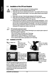
Please make sure that supports HT Technology - Fig. 3 Notice the small gold colored triangle located on the CPU prior to the CPU during installation.) GA-8I915PC Duo Motherboard - 12 - Align the indented corner of the CPU with the following platform components: - Please take note of the one indented corner of the CPU ...
Please make sure that supports HT Technology - Fig. 3 Notice the small gold colored triangle located on the CPU prior to the CPU during installation.) GA-8I915PC Duo Motherboard - 12 - Align the indented corner of the CPU with the following platform components: - Please take note of the one indented corner of the CPU ...

Manual
Page 14
... and specifications. Memory modules are unable to lock the DIMM module. English 1-4 Installation of Memory Before installing the memory modules, please comply with each slot. GA-8I915PC Duo Motherboard - 14 - Please make sure that the memory used . 2. Then push it down. Before installing or removing memory modules, please make sure that the computer...
... and specifications. Memory modules are unable to lock the DIMM module. English 1-4 Installation of Memory Before installing the memory modules, please comply with each slot. GA-8I915PC Duo Motherboard - 14 - Please make sure that the memory used . 2. Then push it down. Before installing or removing memory modules, please make sure that the computer...

Manual
Page 15
... supported. - 15 - Two DDR/DDR II memory modules are installed (the same memory size and type): The Dual Channel Technology will add double. Hardware Installation GA-8I915PC Duo includes 4 DIMM sockets, and each Channel has two DIMM sockets as following: Channel A : DDR 1 or Channel A : DDR II 1 Channel B : DDR 2 Channel B : DDR II 2 If you... of Intel chipset specifications. 1. The following explanations due to slot two DDR/DDR II memory modules into Channel A and B. English Dual Channel DDR/DDR II GA-8I915PC Duo supports the Dual Channel Technology.
... supported. - 15 - Two DDR/DDR II memory modules are installed (the same memory size and type): The Dual Channel Technology will add double. Hardware Installation GA-8I915PC Duo includes 4 DIMM sockets, and each Channel has two DIMM sockets as following: Channel A : DDR 1 or Channel A : DDR II 1 Channel B : DDR 2 Channel B : DDR II 2 If you... of Intel chipset specifications. 1. The following explanations due to slot two DDR/DDR II memory modules into Channel A and B. English Dual Channel DDR/DDR II GA-8I915PC Duo supports the Dual Channel Technology.
Manual
Page 16
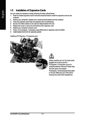
... into expansion slot in the slot. 5. Install related driver from the computer. 3. Be sure the metal contacts on the card are indeed seated in motherboard. 4. GA-8I915PC Duo Motherboard - 16 - English 1-5 Installation of Expansion Cards You can install your expansion card by the small white-drawable bar.
... into expansion slot in the slot. 5. Install related driver from the computer. 3. Be sure the metal contacts on the card are indeed seated in motherboard. 4. GA-8I915PC Duo Motherboard - 16 - English 1-5 Installation of Expansion Cards You can install your expansion card by the small white-drawable bar.
Manual
Page 18
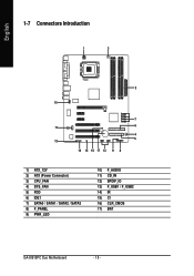
English 1-7 Connectors Introduction 1 3 2 10 7 11 6 4 5 12 14 15 16 17 13 9 8 1) ATX_12V 2) ATX (Power Connector) 3) CPU_FAN 4) SYS_FAN 5) FDD 6) IDE1 7) SATA0 / SATA1 / SATA2 / SATA3 8) F_PANEL 9) PWR_LED 10) F_AUDIO 11) CD_IN 12) SPDIF_IO 13) F_USB1 / F_USB2 14) IR 15) CI 16) CLR_CMOS 17) BAT GA-8I915PC Duo Motherboard - 18 -
English 1-7 Connectors Introduction 1 3 2 10 7 11 6 4 5 12 14 15 16 17 13 9 8 1) ATX_12V 2) ATX (Power Connector) 3) CPU_FAN 4) SYS_FAN 5) FDD 6) IDE1 7) SATA0 / SATA1 / SATA2 / SATA3 8) F_PANEL 9) PWR_LED 10) F_AUDIO 11) CD_IN 12) SPDIF_IO 13) F_USB1 / F_USB2 14) IR 15) CI 16) CLR_CMOS 17) BAT GA-8I915PC Duo Motherboard - 18 -
Manual
Page 20
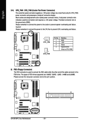
... wire indicates a positive connection and requires a +12V power voltage. Caution! Please remember to connect the power to the cooler to the pin1 position. 2 34 1 33 GA-8I915PC Duo Motherboard - 20 - Please remember to connect the power to the CPU fan to prevent CPU overheating and failure. 1 CPU_FAN 1 SYS_FAN Pin No. 1 2 3 4 Definition GND +12V...
... wire indicates a positive connection and requires a +12V power voltage. Caution! Please remember to connect the power to the cooler to the pin1 position. 2 34 1 33 GA-8I915PC Duo Motherboard - 20 - Please remember to connect the power to the CPU fan to prevent CPU overheating and failure. 1 CPU_FAN 1 SYS_FAN Pin No. 1 2 3 4 Definition GND +12V...

Manual
Page 22
... assignment below. Pin 3: NC Pin 4: Data(-) Open: Normal Close: Reset Hardware System Open: Normal Close: Power On/Off Pin 1: LED anode(+) Pin 2: LED cathode(-) NC GA-8I915PC Duo Motherboard - 22 - Message LED/ Power/ Sleep LED Speaker Connector Power Switch MSG+ MSG- PW+ PWSPEAK+ SPEAK- 2 20 1 19 HD+ HD- RESRES+ NC Reset Switch IDE...
... assignment below. Pin 3: NC Pin 4: Data(-) Open: Normal Close: Reset Hardware System Open: Normal Close: Power On/Off Pin 1: LED anode(+) Pin 2: LED cathode(-) NC GA-8I915PC Duo Motherboard - 22 - Message LED/ Power/ Sleep LED Speaker Connector Power Switch MSG+ MSG- PW+ PWSPEAK+ SPEAK- 2 20 1 19 HD+ HD- RESRES+ NC Reset Switch IDE...
Manual
Page 24
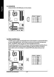
... has digital output function. Use SPDIF IN feature only when your local dealer. 26 15 Pin No. 1 2 3 4 5 6 Definition Power No Pin SPDIF SPDIFI GND GND GA-8I915PC Duo Motherboard - 24 - English 11) CD_IN (CD IN) Connect CD-ROM or DVD-ROM audio out to work or even damage it. Definition 1 1 CD-L 2 GND 3 GND...
... has digital output function. Use SPDIF IN feature only when your local dealer. 26 15 Pin No. 1 2 3 4 5 6 Definition Power No Pin SPDIF SPDIFI GND GND GA-8I915PC Duo Motherboard - 24 - English 11) CD_IN (CD IN) Connect CD-ROM or DVD-ROM audio out to work or even damage it. Definition 1 1 CD-L 2 GND 3 GND...
Manual
Page 26
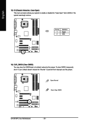
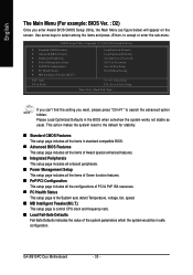
Pin No. Open: Normal 1 1 Short: Clear CMOS GA-8I915PC Duo Motherboard - 26 - To clear CMOS, temporarily short 1-2 pin. Default doesn't include the "Shunter" to prevent from improper use this jumper. English 15) CI (Chassis Intrusion, Case Open) This 2-pin connector allows your system to its default values by this jumper. Definition 1 1 Signal 2 GND 16) CLR_CMOS (Clear CMOS) You may clear the CMOS data to enable or disable the "Case Open" item in BIOS, if the system case begin remove.
Pin No. Open: Normal 1 1 Short: Clear CMOS GA-8I915PC Duo Motherboard - 26 - To clear CMOS, temporarily short 1-2 pin. Default doesn't include the "Shunter" to prevent from improper use this jumper. English 15) CI (Chassis Intrusion, Case Open) This 2-pin connector allows your system to its default values by this jumper. Definition 1 1 Signal 2 GND 16) CLR_CMOS (Clear CMOS) You may clear the CMOS data to enable or disable the "Case Open" item in BIOS, if the system case begin remove.
Manual
Page 30
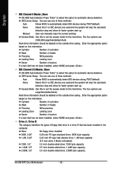
... in the BIOS when somehow the system works not stable as figure below) will appear on the screen. Please Load Optimized Defaults in safe configuration. GA-8I915PC Duo Motherboard - 30 - English The Main Menu (For example: BIOS Ver. : D2) Once you want, please press "Ctrl+F1" to search the advanced option hidden. If...
... in the BIOS when somehow the system works not stable as figure below) will appear on the screen. Please Load Optimized Defaults in safe configuration. GA-8I915PC Duo Motherboard - 30 - English The Main Menu (For example: BIOS Ver. : D2) Once you want, please press "Ctrl+F1" to search the advanced option hidden. If...
Manual
Page 32
... Mode Use this if no IDE devices are : CHS/LBA/Large/Auto(default:Auto) Hard drive information should be labeled on the outside drive casing. GA-8I915PC Duo Motherboard - 32 - User can manually input the correct settings Access Mode Use this option for automatic device detection. IDE Channel 2/3 Master, Slave IDE HDD Auto...
... Mode Use this if no IDE devices are : CHS/LBA/Large/Auto(default:Auto) Hard drive information should be labeled on the outside drive casing. GA-8I915PC Duo Motherboard - 32 - User can manually input the correct settings Access Mode Use this option for automatic device detection. IDE Channel 2/3 Master, Slave IDE HDD Auto...
Manual
Page 34
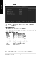
...: Save F6: Fail-Safe Defaults ESC: Exit F1: General Help F7: Optimized Defaults " # " System will show up when you install a processor which supports this menu. GA-8I915PC Duo Motherboard - 34 - Hard Disk Boot Priority Select boot sequence for onboard(or add-on cards) SCSI, RAID, etc.
...: Save F6: Fail-Safe Defaults ESC: Exit F1: General Help F7: Optimized Defaults " # " System will show up when you install a processor which supports this menu. GA-8I915PC Duo Motherboard - 34 - Hard Disk Boot Priority Select boot sequence for onboard(or add-on cards) SCSI, RAID, etc.
Manual
Page 36
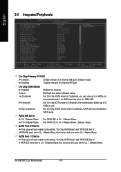
... other for PATA IDE. SATA Port 1/3 Set to This value will auto make by the setting "On-Chip SATA Mode" and "PATA IDE Set to ". GA-8I915PC Duo Motherboard - 36 - English 2-3 Integrated Peripherals CMOS Setup Utility-Copyright (C) 1984-2004 Award Software Integrated Peripherals On-Chip Primary PCI IDE On-Chip SATA Mode x PATA...
... other for PATA IDE. SATA Port 1/3 Set to This value will auto make by the setting "On-Chip SATA Mode" and "PATA IDE Set to ". GA-8I915PC Duo Motherboard - 36 - English 2-3 Integrated Peripherals CMOS Setup Utility-Copyright (C) 1984-2004 Award Software Integrated Peripherals On-Chip Primary PCI IDE On-Chip SATA Mode x PATA...
Manual
Page 38
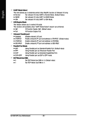
... LPT port and address is 278/IRQ5. 3BC/IRQ7 Enable onboard LPT port and address is 3BC/IRQ7. Using Parallel port as ECP & EPP mode. GA-8I915PC Duo Motherboard - 38 - Normal Set onboard I/O chip UART to Normal Mode. (Default Value) ASKIR IrDA Set onboard I /O chip UART to IrDA Mode. English UART Mode Select...
... LPT port and address is 278/IRQ5. 3BC/IRQ7 Enable onboard LPT port and address is 3BC/IRQ7. Using Parallel port as ECP & EPP mode. GA-8I915PC Duo Motherboard - 38 - Normal Set onboard I/O chip UART to Normal Mode. (Default Value) ASKIR IrDA Set onboard I /O chip UART to IrDA Mode. English UART Mode Select...

Manual
Page 40
... AC-power back to the system, the system always in "On" state. Enter Input password (from 1 to 5 characters to set the Keyboard Power On Password. GA-8I915PC Duo Motherboard - 40 - English Power On By Keyboard Password Disabled Enter from 1 to 5 characters) and press Enter to set the Keyboard Power On password. AC Back...
... AC-power back to the system, the system always in "On" state. Enter Input password (from 1 to 5 characters to set the Keyboard Power On Password. GA-8I915PC Duo Motherboard - 40 - English Power On By Keyboard Password Disabled Enter from 1 to 5 characters) and press Enter to set the Keyboard Power On password. AC Back...


