Manual
Page 4
... GA-8I915GL-MF Motherboard Layout 6 Block Diagram ...7 Chapter 1 Hardware Installation 9 1-1 Considerations Prior to Installation 9 1-2 Feature Summary 10 1-3 Installation of the CPU and Heatsink 12 1-3-1 Installation of the CPU 12 1-3-2 Installation of the Heatsink 13 1-4 Installation of Memory 14 1-5 Install expansion cards 16 1-6 I/O Back Panel Introduction 17 1-7 Connectors Introduction 18 Chapter 2 BIOS Setup 29 The Main Menu (For example: BIOS Ver. : E3 30 2-1 Standard CMOS Features 32 2-2 Advanced BIOS Features 34 2-3 IntegratedPeripherals 36 2-4 Power Management Setup...
... GA-8I915GL-MF Motherboard Layout 6 Block Diagram ...7 Chapter 1 Hardware Installation 9 1-1 Considerations Prior to Installation 9 1-2 Feature Summary 10 1-3 Installation of the CPU and Heatsink 12 1-3-1 Installation of the CPU 12 1-3-2 Installation of the Heatsink 13 1-4 Installation of Memory 14 1-5 Install expansion cards 16 1-6 I/O Back Panel Introduction 17 1-7 Connectors Introduction 18 Chapter 2 BIOS Setup 29 The Main Menu (For example: BIOS Ver. : E3 30 2-1 Standard CMOS Features 32 2-2 Advanced BIOS Features 34 2-3 IntegratedPeripherals 36 2-4 Power Management Setup...
Manual
Page 10
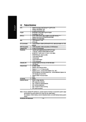
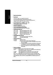
... of 2 FDD devices Š 4 Serial ATA connections Š 1 parallel port supporting Normal/EPP/ECP mode Š 1 VGA port, onboard COMA/COMB connection Š 8 USB 2.0/1.1 ports (rear x 4, front x 4 via cable) Š 3 IEEE1394 ports (requires cable) Š 1 front audio connector Š 1 IR connector Š 1 PS/2 keyboard port Š 1 PS/2 mouse port Š Onboard Realtek 8110S chip (10/100/1000 Mbit) Š 1 RJ 45 port Š ALC880 CODEC Š Supports Jack Sensing function Š Supports 2 / 4 / 6 / 8 channel audio Š Supports Line In ; GA-8I915GL-MF Motherboard - 10...
... of 2 FDD devices Š 4 Serial ATA connections Š 1 parallel port supporting Normal/EPP/ECP mode Š 1 VGA port, onboard COMA/COMB connection Š 8 USB 2.0/1.1 ports (rear x 4, front x 4 via cable) Š 3 IEEE1394 ports (requires cable) Š 1 front audio connector Š 1 IR connector Š 1 PS/2 keyboard port Š 1 PS/2 mouse port Š Onboard Realtek 8110S chip (10/100/1000 Mbit) Š 1 RJ 45 port Š ALC880 CODEC Š Supports Jack Sensing function Š Supports 2 / 4 / 6 / 8 channel audio Š Supports Line In ; GA-8I915GL-MF Motherboard - 10...
Manual
Page 12
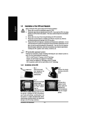
... CPU during installation.) GA-8I915GL-MF Motherboard - 12 - Please make sure the heatsink is properly inserted, please replace the load plate and push the metal lever back into the socket in the wrong direction, the CPU will not insert properly. Please make sure that the system bus frequency be set the frequency beyond hardware specifications since it enabled - Fig. 3 Notice the small gold colored triangle located on the CPU socket...
... CPU during installation.) GA-8I915GL-MF Motherboard - 12 - Please make sure the heatsink is properly inserted, please replace the load plate and push the metal lever back into the socket in the wrong direction, the CPU will not insert properly. Please make sure that the system bus frequency be set the frequency beyond hardware specifications since it enabled - Fig. 3 Notice the small gold colored triangle located on the CPU socket...
Manual
Page 20
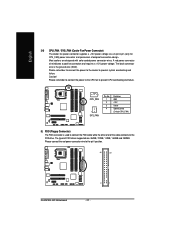
... 33 GA-8I915GL-MF Motherboard 2 1 - 20 - Please connect the red power connector wire to prevent system overheating and failure. The black connector wire is used to the FDD drive. The types of the cable connects to connect the FDD cable while the other end of FDD drives supported are designed with color-coded power connector wires. English 3/4) CPU_FAN / SYS_FAN (Cooler Fan Power Connector) The cooler fan power connector supplies a +12V power voltage via a 3-pin/4-pin (only for CPU_FAN) 5) FDD (Floppy Connector) The FDD connector is the ground wire (GND...
... 33 GA-8I915GL-MF Motherboard 2 1 - 20 - Please connect the red power connector wire to prevent system overheating and failure. The black connector wire is used to the FDD drive. The types of the cable connects to connect the FDD cable while the other end of FDD drives supported are designed with color-coded power connector wires. English 3/4) CPU_FAN / SYS_FAN (Cooler Fan Power Connector) The cooler fan power connector supplies a +12V power voltage via a 3-pin/4-pin (only for CPU_FAN) 5) FDD (Floppy Connector) The FDD connector is the ground wire (GND...
Manual
Page 21
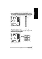
Hardware Installation Pin No. English 6) IDE (IDE Connector) An IDE device connects to connect two IDE devices, please set the jumper on the IDE device). 40 39 2 1 7) SATA0/SATA1/SATA2/SATA3 (Serial ATA Connector, Controlled by ICH6) Serial ATA can then connect to work properly. Please refer to the BIOS setting for information on settings, please refer to the instructions located on one IDE cable, and the single IDE cable can provide 150MB/s transfer rate. One IDE connector can connect to one IDE device as Master...
Hardware Installation Pin No. English 6) IDE (IDE Connector) An IDE device connects to connect two IDE devices, please set the jumper on the IDE device). 40 39 2 1 7) SATA0/SATA1/SATA2/SATA3 (Serial ATA Connector, Controlled by ICH6) Serial ATA can then connect to work properly. Please refer to the BIOS setting for information on settings, please refer to the instructions located on one IDE cable, and the single IDE cable can provide 150MB/s transfer rate. One IDE connector can connect to one IDE device as Master...
Manual
Page 22
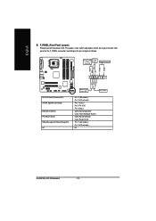
...GA-8I915GL-MF Motherboard - 22 - English 8) F_PANEL (Front Panel Jumper) Please connect the power LED, PC peaker, reset switch and power switch etc of your chassis front panel to the F_PANEL connector according to the pin assignment below. Message LED/ Power/ Sleep LED Power Switch Speaker Connector SPEAK- SPEAK+ PWPW+ MSGMSG+ 2 20 1 19 NC RES+ RESHD- HD+ HD (IDE Hard Disk Active LED) SPEAK (Speaker Connector) RES (Reset Switch) PW (Power Switch) MSG(Message LED/Power/Sleep LED) NC IDE Hard Disk Active LED Reset Switch Pin 1: LED anode(+) Pin 2: LED cathode(-) Pin 1: VCC(+) Pin...
...GA-8I915GL-MF Motherboard - 22 - English 8) F_PANEL (Front Panel Jumper) Please connect the power LED, PC peaker, reset switch and power switch etc of your chassis front panel to the F_PANEL connector according to the pin assignment below. Message LED/ Power/ Sleep LED Power Switch Speaker Connector SPEAK- SPEAK+ PWPW+ MSGMSG+ 2 20 1 19 NC RES+ RESHD- HD+ HD (IDE Hard Disk Active LED) SPEAK (Speaker Connector) RES (Reset Switch) PW (Power Switch) MSG(Message LED/Power/Sleep LED) NC IDE Hard Disk Active LED Reset Switch Pin 1: LED anode(+) Pin 2: LED cathode(-) Pin 1: VCC(+) Pin...
Manual
Page 30
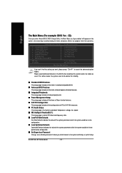
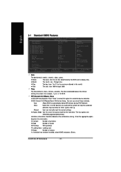
... & Exit Setup Exit Without Saving KLJI: Select Item F10: Save & Exit Setup Time, Date, Hard Disk Type... This action makes the system reset to Setup. It allows you want, please press "Ctrl+F1" to accept or enter the sub-menu. Please Load Optimized Defaults in best performance configuration. „ Set Supervisor Password Change, set, or disable password. English The Main Menu (For example: BIOS Ver. : E3) Once you enter Award BIOS CMOS Setup Utility, the Main Menu (as usual. GA-8I915GL-MF Motherboard...
... & Exit Setup Exit Without Saving KLJI: Select Item F10: Save & Exit Setup Time, Date, Hard Disk Type... This action makes the system reset to Setup. It allows you want, please press "Ctrl+F1" to accept or enter the sub-menu. Please Load Optimized Defaults in best performance configuration. „ Set Supervisor Password Change, set, or disable password. English The Main Menu (For example: BIOS Ver. : E3) Once you enter Award BIOS CMOS Setup Utility, the Main Menu (as usual. GA-8I915GL-MF Motherboard...
Manual
Page 32
... a hard disk has not been installed, select NONE and press . GA-8I915GL-MF Motherboard - 32 - to Dec. 1 to 31 (or maximum allowed in . The time is , , , . For example, 1 p.m. Through Dec. You can manually input the correct settings Access Mode Use this to automatically detect IDE devices during POST(default) None Select this if no IDE devices are : CHS/LBA/Large/Auto(default:Auto) Hard drive information should be labeled on the outside drive casing. Cylinder...
... a hard disk has not been installed, select NONE and press . GA-8I915GL-MF Motherboard - 32 - to Dec. 1 to 31 (or maximum allowed in . The time is , , , . For example, 1 p.m. Through Dec. You can manually input the correct settings Access Mode Use this to automatically detect IDE devices during POST(default) None Select this if no IDE devices are : CHS/LBA/Large/Auto(default:Auto) Hard drive information should be labeled on the outside drive casing. Cylinder...

Manual
Page 41
... to PCI 1. (Default value) Set IRQ 3,4,5,7,9,10,11,12,14,15 to PCI 2. 2-6 PC Health Status CMOS Setup Utility-Copyright (C) 1984-2005 Award Software PC Health Status Reset Case Open Status Case Opened Vcore DDR25V +3.3V +12V Current CPU Temperature Current CPU FAN Speed Current SYSTEM FAN Speed CPU Warning Temperature CPU FAN Fail Warning SYSTEM FAN Fail Warning CPU Smart FAN Control CPU Smart FAN Mode [Disabled] Yes OK OK OK OK 33oC 4687 RPM 0 RPM [Disabled] [Disabled] [Disabled] [Enabled] [Auto] Item Help Menu Level` KLJI: Move Enter: Select...
... to PCI 1. (Default value) Set IRQ 3,4,5,7,9,10,11,12,14,15 to PCI 2. 2-6 PC Health Status CMOS Setup Utility-Copyright (C) 1984-2005 Award Software PC Health Status Reset Case Open Status Case Opened Vcore DDR25V +3.3V +12V Current CPU Temperature Current CPU FAN Speed Current SYSTEM FAN Speed CPU Warning Temperature CPU FAN Fail Warning SYSTEM FAN Fail Warning CPU Smart FAN Control CPU Smart FAN Mode [Disabled] Yes OK OK OK OK 33oC 4687 RPM 0 RPM [Disabled] [Disabled] [Disabled] [Enabled] [Auto] Item Help Menu Level` KLJI: Move Enter: Select...
Manual
Page 42
..., the Voltage option can be used for it. (Default Value) Voltage Set to Voltage when you installed and sets the optimal CPU Smart FAN control mode for CPU fans with a 4-pin fan power cable. CPU Smart FAN Control Disabled Disable this function. (Default value) CPU/SYSTEM FAN Fail Warning Disabled Fan warning function disable. (Default value) Enabled Fan warning function enable. GA-8I915GL-MF Motherboard - 42 - If the case have been opened, "Case Opened" will not effectively reduce the fan speed. CPU Warning Temperature 60oC / 140oF Monitor CPU temperature at 60oC...
..., the Voltage option can be used for it. (Default Value) Voltage Set to Voltage when you installed and sets the optimal CPU Smart FAN control mode for CPU fans with a 4-pin fan power cable. CPU Smart FAN Control Disabled Disable this function. (Default value) CPU/SYSTEM FAN Fail Warning Disabled Fan warning function disable. (Default value) Enabled Fan warning function enable. GA-8I915GL-MF Motherboard - 42 - If the case have been opened, "Case Opened" will not effectively reduce the fan speed. CPU Warning Temperature 60oC / 140oF Monitor CPU temperature at 60oC...
Manual
Page 45
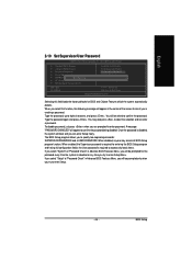
... 2-10 Set Supervisor/User Password CMOS Setup Utility-Copyright (C) 1984-2005 Award Software ` Standard CMOS Features ` Advanced BIOS Features ` Integrated Peripherals ` Power Management Setup ` PnP/PCI ConfigurationEsnter Password: ` PC Health Status ` MB Intelligent Tweaker(M.I.T.) ESC: Quit F8: Q-Flash Load Fail-Safe Defaults Load Optimized Defaults Set Supervisor Password Set User Password Save & Exit Setup Exit Without Saving KLJI: Select Item F10: Save & Exit Setup Change/Set/Disable Password Selecting this function, the following message will boot and you can enter Setup freely...
... 2-10 Set Supervisor/User Password CMOS Setup Utility-Copyright (C) 1984-2005 Award Software ` Standard CMOS Features ` Advanced BIOS Features ` Integrated Peripherals ` Power Management Setup ` PnP/PCI ConfigurationEsnter Password: ` PC Health Status ` MB Intelligent Tweaker(M.I.T.) ESC: Quit F8: Q-Flash Load Fail-Safe Defaults Load Optimized Defaults Set Supervisor Password Set User Password Save & Exit Setup Exit Without Saving KLJI: Select Item F10: Save & Exit Setup Change/Set/Disable Password Selecting this function, the following message will boot and you can enter Setup freely...
Manual
Page 47
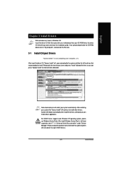
... system (System will auto start and show a question mark "?" English Chapter 3 Install Drivers Pictures below are shown in "My computer", and execute the Run.exe. 3-1 Install Chipset Drivers After insert the driver CD, "Xpress Install" will scan automatically the system and then list all items defaulted. Insert the driver CD-title that came with your motherboard into your CD-ROM drive, the driver CD-title will...
... system (System will auto start and show a question mark "?" English Chapter 3 Install Drivers Pictures below are shown in "My computer", and execute the Run.exe. 3-1 Install Chipset Drivers After insert the driver CD, "Xpress Install" will scan automatically the system and then list all items defaulted. Insert the driver CD-title that came with your motherboard into your CD-ROM drive, the driver CD-title will...
Manual
Page 51
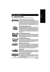
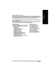
... CPU system bus, memory timings or to enabled Gigabyte's unique C.I.A. 2 and M.I .T.'s integration of all platform performance settings into different modes within BIOS setup in order to change system settings such as displaying a detailed list of programs. When the function is disabled, the CPU is a revolutionary eight-phase power circuit built for download. Download Center automatically runs a system check of system loading. English Chapter 4 Appendix 4-1 Unique Software Utilities (Not all model support these Unique Software Utilities...
... CPU system bus, memory timings or to enabled Gigabyte's unique C.I.A. 2 and M.I .T.'s integration of all platform performance settings into different modes within BIOS setup in order to change system settings such as displaying a detailed list of programs. When the function is disabled, the CPU is a revolutionary eight-phase power circuit built for download. Download Center automatically runs a system check of system loading. English Chapter 4 Appendix 4-1 Unique Software Utilities (Not all model support these Unique Software Utilities...
Manual
Page 52
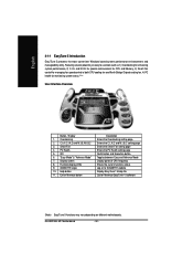
... powerful yet easy to GIGABYTE website Display EasyTuneTM 5 Help file Quit or Minimize EasyTuneTM 5 software (Note) EasyTune 5 functions may vary depending on to use tools such as 1) Overclocking for monitoring system status.(Note) User Interface Overview Button / Display 1. "Easy Mode" & "Advance Mode" 7. Help button 11. GA-8I915GL-MF Motherboard - 52 - GIGABYTE Logo 10. C.I.A./C.I.A.2 and M.I.B./M.I .A. Display screen 8. Function display LEDs 9. Exit or Minimize button Description Enters the Overclocking setting page Enters the C.I.A./2 and M.I .B. Smart-Fan...
... powerful yet easy to GIGABYTE website Display EasyTuneTM 5 Help file Quit or Minimize EasyTuneTM 5 software (Note) EasyTune 5 functions may vary depending on to use tools such as 1) Overclocking for monitoring system status.(Note) User Interface Overview Button / Display 1. "Easy Mode" & "Advance Mode" 7. Help button 11. GA-8I915GL-MF Motherboard - 52 - GIGABYTE Logo 10. C.I.A./C.I.A.2 and M.I.B./M.I .A. Display screen 8. Function display LEDs 9. Exit or Minimize button Description Enters the Overclocking setting page Enters the C.I.A./2 and M.I .B. Smart-Fan...
Manual
Page 57
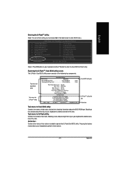
... and pressing Enter key on your keyboard to enter the Dual BIOS/Q-Flash utility. CMOS Setup Utility-Copyright (C) 1984-2004 Award Software Standard CMOS Features Advanced BIOS Features Integrated Peripherals Power Management Setup PnP/PCI Configurations PC Health Status MB Intelligent Tweaker(M.I.T.) ESC: Quit F8: Dual BIOS/Q-Flash Select Language Load Fail-Safe Defaults Load Optimized Defaults Set Supervisor Password Set User Password Save & Exit Setup Exit Without Saving F3: Change Language F10: Save & Exit Setup Time, Date, Hard Disk Type... Pressing the buttons mentioned on...
... and pressing Enter key on your keyboard to enter the Dual BIOS/Q-Flash utility. CMOS Setup Utility-Copyright (C) 1984-2004 Award Software Standard CMOS Features Advanced BIOS Features Integrated Peripherals Power Management Setup PnP/PCI Configurations PC Health Status MB Intelligent Tweaker(M.I.T.) ESC: Quit F8: Dual BIOS/Q-Flash Select Language Load Fail-Safe Defaults Load Optimized Defaults Set Supervisor Password Set User Password Save & Exit Setup Exit Without Saving F3: Change Language F10: Save & Exit Setup Time, Date, Hard Disk Type... Pressing the buttons mentioned on...
Manual
Page 58
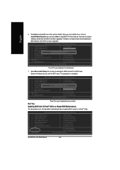
... to flash BIOS. GA-8I915GL-MF Motherboard - 58 - Later, you will see a box pop up showing the BIOS files you how to update BIOS using the Q-Flash utility. As described in the floppy disk. Press arrow buttons on your keyboard to move the light bar to "Load Main BIOS from Floppy Save Main BIOS to Floppy Save Backup BIOS to Floppy Enter : Run :Move ESC:Reset F10:Power Off BIOS file in the "Before you begin Step 1 with "Save Main BIOS to Floppy" item. 2. English Using...
... to flash BIOS. GA-8I915GL-MF Motherboard - 58 - Later, you will see a box pop up showing the BIOS files you how to update BIOS using the Q-Flash utility. As described in the floppy disk. Press arrow buttons on your keyboard to move the light bar to "Load Main BIOS from Floppy Save Main BIOS to Floppy Save Backup BIOS to Floppy Enter : Run :Move ESC:Reset F10:Power Off BIOS file in the "Before you begin Step 1 with "Save Main BIOS to Floppy" item. 2. English Using...

Manual
Page 59
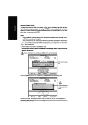
... then Y button to the Q-Flash menu when the BIOS updating procedure is completed. Load Default Settings Save Settings to CMOS Q-Flash Utility Load Main BIOS from Floppy Load Backup BIOS from Floppy Save Main BIOS to Floppy Save Backup BIOS to Floppy Enter : Run :Move ESC:Reset F10:Power Off You can repeat Step 1 to 4 to Floppy Enter : Run :Move ESC:Reset F10:Power Off After system reboots, you may find the BIOS version on your boot screen becomes the one you flashed. Award Modular BIOS v6.00PG...
... then Y button to the Q-Flash menu when the BIOS updating procedure is completed. Load Default Settings Save Settings to CMOS Q-Flash Utility Load Main BIOS from Floppy Load Backup BIOS from Floppy Save Main BIOS to Floppy Save Backup BIOS to Floppy Enter : Run :Move ESC:Reset F10:Power Off You can repeat Step 1 to 4 to Floppy Enter : Run :Move ESC:Reset F10:Power Off After system reboots, you may find the BIOS version on your boot screen becomes the one you flashed. Award Modular BIOS v6.00PG...
Manual
Page 60
... to update BIOS using the Q-FlashTM utility. This part guides users of single-BIOS motherboards how to enter BIOS menu after you are in BIOS menu, move to Load Fail-Safe Defaults item and press Enter to save the settings to CMOS and EXIT (SYe/tNS)u?pYervisor Password PnP/PCI Configurations Set User Password PC Health Status Save & Exit Setup MB Intelligent Tweaker(M.I.T.) Exit Without Saving ESC: Quit F8: Dual BIOS/Q-Flash F3: Change Language F10: Save & Exit Setup Time, Date, Hard Disk Type... GA-8I915GL-MF Motherboard - 60 - CMOS Setup Utility...
... to update BIOS using the Q-FlashTM utility. This part guides users of single-BIOS motherboards how to enter BIOS menu after you are in BIOS menu, move to Load Fail-Safe Defaults item and press Enter to save the settings to CMOS and EXIT (SYe/tNS)u?pYervisor Password PnP/PCI Configurations Set User Password PC Health Status Save & Exit Setup MB Intelligent Tweaker(M.I.T.) Exit Without Saving ESC: Quit F8: Dual BIOS/Q-Flash F3: Change Language F10: Save & Exit Setup Time, Date, Hard Disk Type... GA-8I915GL-MF Motherboard - 60 - CMOS Setup Utility...
Manual
Page 70
... after it aside for one minute). 4. Turn off the on-board battery to leak voltage to see some boards, a small amount of my keyboard/optical mouse still on after updating BIOS. Answer: Gigabyte motherboards will be able to clear CMOS. English 4-2 Troubleshooting Below is still on. However, if the system instability still remains, please clear CMOS to disable the onboard VGA. If not, please change any setting manually to solve the problem.
... after it aside for one minute). 4. Turn off the on-board battery to leak voltage to see some boards, a small amount of my keyboard/optical mouse still on after updating BIOS. Answer: Gigabyte motherboards will be able to clear CMOS. English 4-2 Troubleshooting Below is still on. However, if the system instability still remains, please clear CMOS to disable the onboard VGA. If not, please change any setting manually to solve the problem.
Manual
Page 71
... 7 beeps Processor exception interrupt error 8 beeps Display memory read/write failure 9 beeps ROM checksum error 10 beeps CMOS shutdown register read/write error 11 beeps Cache memory bad AWARD BIOS Beep Codes 1 short: System boots successfully 2 short: CMOS setting error 1 long 1 short: DRAM or M/B error 1 long 2 short: Monitor or display card error 1 long 3 short: Keyboard error 1 long 9 short: BIOS ROM error Continuous long beeps: DRAM error Continuous short beeps: Power error - 71 - Answer: Please refer to the user manual and check whether you identify the possible computer problems...
... 7 beeps Processor exception interrupt error 8 beeps Display memory read/write failure 9 beeps ROM checksum error 10 beeps CMOS shutdown register read/write error 11 beeps Cache memory bad AWARD BIOS Beep Codes 1 short: System boots successfully 2 short: CMOS setting error 1 long 1 short: DRAM or M/B error 1 long 2 short: Monitor or display card error 1 long 3 short: Keyboard error 1 long 9 short: BIOS ROM error Continuous long beeps: DRAM error Continuous short beeps: Power error - 71 - Answer: Please refer to the user manual and check whether you identify the possible computer problems...


