Manual
Page 1
GA-8I915GL-MF Intel® Pentium® 4 LGA775 Processor Motherboard User's Manual Rev. 1001 12ME-I915GLMF-1001
GA-8I915GL-MF Intel® Pentium® 4 LGA775 Processor Motherboard User's Manual Rev. 1001 12ME-I915GLMF-1001
Manual
Page 2
Motherboard GA-8I915GL-MF Feb. 22, 2005 Motherboard GA-8I915GL-MF Feb. 22, 2005
Motherboard GA-8I915GL-MF Feb. 22, 2005 Motherboard GA-8I915GL-MF Feb. 22, 2005
Manual
Page 4
Table of Content GA-8I915GL-MF Motherboard Layout 6 Block Diagram ...7 Chapter 1 Hardware Installation 9 1-1 Considerations Prior to Installation 9 1-2 Feature Summary 10 1-3 Installation of the CPU and Heatsink 12 1-3-1 Installation of the CPU ...
Table of Content GA-8I915GL-MF Motherboard Layout 6 Block Diagram ...7 Chapter 1 Hardware Installation 9 1-1 Considerations Prior to Installation 9 1-2 Feature Summary 10 1-3 Installation of the CPU and Heatsink 12 1-3-1 Installation of the CPU ...
Manual
Page 6
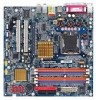
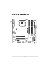
SYS_FAN CI IR GA-8I915GL-MF Motherboard Layout IT8712 KB_MS SPDIF_O SPDIF_I CPU_FAN ATX VGA LPT R_USB ATX_12V LGA775 GA-8I915GL-MF DDR1 DDR2 USB LAN AZALIA_FP AUDIO1 AUDIO2 RTL8110S CD_IN CODEC PCIE_1 COMA COMB Intel 915GL IDE FDD DDR3 DDR4 PCI1 BAT PCI2 TSB43AB23 ICH6 SATA3 SATA2 SATA1 SATA0 F2_1394 F1_1394 F_USB1 F_USB2 BIOS F_PANEL CLR_CMOS - 6 -
SYS_FAN CI IR GA-8I915GL-MF Motherboard Layout IT8712 KB_MS SPDIF_O SPDIF_I CPU_FAN ATX VGA LPT R_USB ATX_12V LGA775 GA-8I915GL-MF DDR1 DDR2 USB LAN AZALIA_FP AUDIO1 AUDIO2 RTL8110S CD_IN CODEC PCIE_1 COMA COMB Intel 915GL IDE FDD DDR3 DDR4 PCI1 BAT PCI2 TSB43AB23 ICH6 SATA3 SATA2 SATA1 SATA0 F2_1394 F1_1394 F_USB1 F_USB2 BIOS F_PANEL CLR_CMOS - 6 -
Manual
Page 10
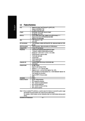
... chip (10/100/1000 Mbit) Š 1 RJ 45 port Š ALC880 CODEC Š Supports Jack Sensing function Š Supports 2 / 4 / 6 / 8 channel audio Š Supports Line In ; GA-8I915GL-MF Motherboard - 10 - Line Out (Front Speaker Out) ; MIC ; For example, 4 GB of memory size will instead be shown as 3.xxGB memory during system startup. English...
... chip (10/100/1000 Mbit) Š 1 RJ 45 port Š ALC880 CODEC Š Supports Jack Sensing function Š Supports 2 / 4 / 6 / 8 channel audio Š Supports Line In ; GA-8I915GL-MF Motherboard - 10 - Line Out (Front Speaker Out) ; MIC ; For example, 4 GB of memory size will instead be shown as 3.xxGB memory during system startup. English...
Manual
Page 12
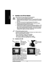
..., carefully place it into its original position. If you wish to set beyond the proper specifications, please do so according to the CPU during installation.) GA-8I915GL-MF Motherboard - 12 - It is not recommended that the motherboard supports the CPU. 2. OS: An operation system that supports HT Technology - Please make sure that the...
..., carefully place it into its original position. If you wish to set beyond the proper specifications, please do so according to the CPU during installation.) GA-8I915GL-MF Motherboard - 12 - It is not recommended that the motherboard supports the CPU. 2. OS: An operation system that supports HT Technology - Please make sure that the...
Manual
Page 14
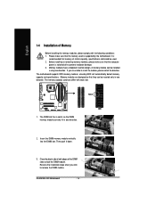
... module vertically into the DIMM slot. Close the plastic clip at both edges of Memory Before installing the memory modules, please comply with each slot. GA-8I915GL-MF Motherboard - 14 - English 1-4 Installation of the DIMM slots to lock the DIMM module. Memory modules are unable to remove the DIMM module. Then push it...
... module vertically into the DIMM slot. Close the plastic clip at both edges of Memory Before installing the memory modules, please comply with each slot. GA-8I915GL-MF Motherboard - 14 - English 1-4 Installation of the DIMM slots to lock the DIMM module. Memory modules are unable to remove the DIMM module. Then push it...
Manual
Page 15
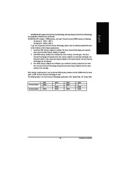
.../three DDR memory module is installed: The Dual Channel Technology can't operate when only one DDR memory module is for Dual Channel Technology to work. GA-8I915GL-MF includes 4 DIMM sockets, and each Channel has two DIMM sockets as following: Channel A : DDR 1, DDR 2 Channel B : DDR 3, DDR 4 If you... the same channel, the Dual Channel Technology will operate only when those modules have the same memory size and type. English GA-8I915GL-MF supports the Dual Channel Technology. Two DDR memory modules are installed (the same memory size and type): The Dual Channel Technology will double...
.../three DDR memory module is installed: The Dual Channel Technology can't operate when only one DDR memory module is for Dual Channel Technology to work. GA-8I915GL-MF includes 4 DIMM sockets, and each Channel has two DIMM sockets as following: Channel A : DDR 1, DDR 2 Channel B : DDR 3, DDR 4 If you... the same channel, the Dual Channel Technology will operate only when those modules have the same memory size and type. English GA-8I915GL-MF supports the Dual Channel Technology. Two DDR memory modules are installed (the same memory size and type): The Dual Channel Technology will double...
Manual
Page 16
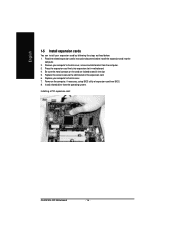
.... 4. Remove your computer's chassis cover, screws and slot bracket from the operating system. Press the expansion card firmly into the computer. 2. Installing a PCI expansion card: GA-8I915GL-MF Motherboard - 16 -
.... 4. Remove your computer's chassis cover, screws and slot bracket from the operating system. Press the expansion card firmly into the computer. 2. Installing a PCI expansion card: GA-8I915GL-MF Motherboard - 16 -
Manual
Page 18
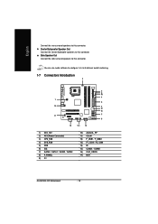
... 7) SATA0 / SATA1 / SATA2 / SATA3 8) F_PANEL 9) CI 10) AZALIA_FP 11) CD_IN 12) F_USB1 / F_USB2 13) F1_1394 / F2_1394 14) IR 15) COMA / COMB 16) CLR_CMOS 17) BAT GA-8I915GL-MF Motherboard - 18 - English Connect the rear surround speakers to this connector. Side Speaker Out Connect the side surround speakers to this connector.
... 7) SATA0 / SATA1 / SATA2 / SATA3 8) F_PANEL 9) CI 10) AZALIA_FP 11) CD_IN 12) F_USB1 / F_USB2 13) F1_1394 / F2_1394 14) IR 15) COMA / COMB 16) CLR_CMOS 17) BAT GA-8I915GL-MF Motherboard - 18 - English Connect the rear surround speakers to this connector. Side Speaker Out Connect the side surround speakers to this connector.
Manual
Page 20
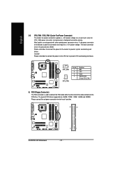
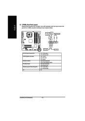
Caution! Please remember to connect the power to the cooler to the pin1 position. 34 33 GA-8I915GL-MF Motherboard 2 1 - 20 - Most coolers are : 360KB, 720KB, 1.2MB, 1.44MB and 2.88MB. Please connect the red power connector wire to prevent system overheating and failure. Please ...
Caution! Please remember to connect the power to the cooler to the pin1 position. 34 33 GA-8I915GL-MF Motherboard 2 1 - 20 - Most coolers are : 360KB, 720KB, 1.2MB, 1.44MB and 2.88MB. Please connect the red power connector wire to prevent system overheating and failure. Please ...
Manual
Page 22
Pin 3: NC Pin 4: Data(-) Open: Normal Operation Close: Reset Hardware System Open: Normal Operation Close: Power On/Off Pin 1: LED anode(+) Pin 2: LED cathode(-) NC GA-8I915GL-MF Motherboard - 22 - HD+ HD (IDE Hard Disk Active LED) SPEAK (Speaker Connector) RES (Reset Switch) PW (Power Switch) MSG(Message LED/Power/Sleep LED) NC ...
Pin 3: NC Pin 4: Data(-) Open: Normal Operation Close: Reset Hardware System Open: Normal Operation Close: Power On/Off Pin 1: LED anode(+) Pin 2: LED cathode(-) NC GA-8I915GL-MF Motherboard - 22 - HD+ HD (IDE Hard Disk Active LED) SPEAK (Speaker Connector) RES (Reset Switch) PW (Power Switch) MSG(Message LED/Power/Sleep LED) NC ...
Manual
Page 24
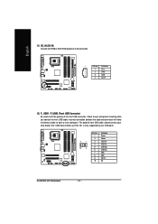
..." is only supported by rear USB ports. Definition 1 Power 2 Power 9 1 3 USB DX- 4 USB Dy- 10 2 5 USB DX+ 6 USB Dy+ 7 GND 8 GND 9 No Pin 10 NC GA-8I915GL-MF Motherboard - 24 - Pin No. English 11) CD_IN (CD IN) Connect CD-ROM or DVD-ROM audio out to work or even damage it. Definition 1 CD...
..." is only supported by rear USB ports. Definition 1 Power 2 Power 9 1 3 USB DX- 4 USB Dy- 10 2 5 USB DX+ 6 USB Dy+ 7 GND 8 GND 9 No Pin 10 NC GA-8I915GL-MF Motherboard - 24 - Pin No. English 11) CD_IN (CD IN) Connect CD-ROM or DVD-ROM audio out to work or even damage it. Definition 1 CD...
Manual
Page 26
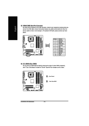
... careful with the polarity of the COM connector. Default doesn't include the "Shunter" to its default values by this jumper. 1 Open: Normal 1 Short :Clear CMOS GA-8I915GL-MF Motherboard - 26 - For optional COM cable, please contact your local dealer. 2 10 1 9 Pin No. 1 2 3 4 5 6 7 8 9 10 Definition NDCD A/BNSIN A/B NSOUT A/B NDTR A/BGND NDSR A/BNRTS A/BNCTS A/BNRI...
... careful with the polarity of the COM connector. Default doesn't include the "Shunter" to its default values by this jumper. 1 Open: Normal 1 Short :Clear CMOS GA-8I915GL-MF Motherboard - 26 - For optional COM cable, please contact your local dealer. 2 10 1 9 Pin No. 1 2 3 4 5 6 7 8 9 10 Definition NDCD A/BNSIN A/B NSOUT A/B NDTR A/BGND NDSR A/BNRTS A/BNCTS A/BNRI...
Manual
Page 30
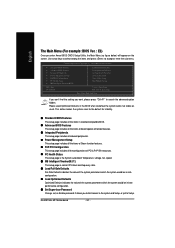
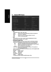
... Defaults Set Supervisor Password Set User Password Save & Exit Setup Exit Without Saving KLJI: Select Item F10: Save & Exit Setup Time, Date, Hard Disk Type... GA-8I915GL-MF Motherboard - 30 - It allows you want, please press "Ctrl+F1" to accept or enter the sub-menu. CMOS Setup Utility-Copyright (C) 1984-2005 Award Software...
... Defaults Set Supervisor Password Set User Password Save & Exit Setup Exit Without Saving KLJI: Select Item F10: Save & Exit Setup Time, Date, Hard Disk Type... GA-8I915GL-MF Motherboard - 30 - It allows you want, please press "Ctrl+F1" to accept or enter the sub-menu. CMOS Setup Utility-Copyright (C) 1984-2005 Award Software...
Manual
Page 32
... use one of sectors If a hard disk has not been installed, select NONE and press . to Dec. 1 to 31 (or maximum allowed in . Through Dec. GA-8I915GL-MF Motherboard - 32 - Enter the appropriate option based on the outside drive casing. The time is , , , . Cylinder Number of cylinders Head Number of heads Precomp Write...
... use one of sectors If a hard disk has not been installed, select NONE and press . to Dec. 1 to 31 (or maximum allowed in . Through Dec. GA-8I915GL-MF Motherboard - 32 - Enter the appropriate option based on the outside drive casing. The time is , , , . Cylinder Number of cylinders Head Number of heads Precomp Write...
Manual
Page 34
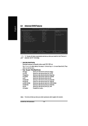
... down the list. Select your boot device priority by LS120. Select your boot device priority by CDROM. Select your boot device priority by USB-CDROM. GA-8I915GL-MF Motherboard - 34 - Press to 3 No-Execute Memory Protect (Note) CPU Enhanced Halt (C1E) (Note) CPU Thermal Monitor 2(TM2) (Note) On-Chip Frame Buffer Size [Press...
... down the list. Select your boot device priority by LS120. Select your boot device priority by CDROM. Select your boot device priority by USB-CDROM. GA-8I915GL-MF Motherboard - 34 - Press to 3 No-Execute Memory Protect (Note) CPU Enhanced Halt (C1E) (Note) CPU Thermal Monitor 2(TM2) (Note) On-Chip Frame Buffer Size [Press...
Manual
Page 36
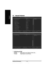
... Help F7: Optimized Defaults On-Chip Primary PCI IDE Enabled Enable onboard 1st channel IDE port. (Default value) Disabled Disable onboard 1st channel IDE port. GA-8I915GL-MF Motherboard - 36 -
... Help F7: Optimized Defaults On-Chip Primary PCI IDE Enabled Enable onboard 1st channel IDE port. (Default value) Disabled Disable onboard 1st channel IDE port. GA-8I915GL-MF Motherboard - 36 -

Manual
Page 38
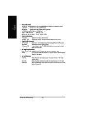
... address is 378/IRQ7. (Default value) Enable onboard LPT port and address is 278/IRQ5. 3BC/IRQ7 Enable onboard LPT port and address is 3E8. GA-8I915GL-MF Motherboard - 38 -
... address is 378/IRQ7. (Default value) Enable onboard LPT port and address is 278/IRQ5. 3BC/IRQ7 Enable onboard LPT port and address is 3E8. GA-8I915GL-MF Motherboard - 38 -
Manual
Page 40
If RTC Alarm Lead To Power On is Enabled. GA-8I915GL-MF Motherboard - 40 - Enter Input password (from 1 to 5 characters to the Last state before AC-power off. AC Back Function Soft-Off When AC-power back ...
If RTC Alarm Lead To Power On is Enabled. GA-8I915GL-MF Motherboard - 40 - Enter Input password (from 1 to 5 characters to the Last state before AC-power off. AC Back Function Soft-Off When AC-power back ...