Manual
Page 4
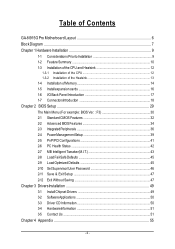
...GA-8I915G Pro Motherboard Layout 6 Block Diagram ...7 Chapter 1 Hardware Installation 9 1-1 Considerations Priorto Installation 9 1-2 Feature Summary 10 1-3 Installation of the CPU and Heatsink 12 1-3-1 Installation of the CPU 12 1-3-2 Installation of the Heatsink 13 1-4 Installation of Memory 14 1-5 Installexpansion cards 16 1-6 I/O Back Panel Introduction 17 1-7 ConnectorsIntroduction 18 Chapter 2 BIOS... Setup 29 The Main Menu (For example: BIOS Ver. : F3 30 2-1 Standard CMOS Features 32 2-2 Advanced BIOS Features 34 2-3 IntegratedPeripherals...
...GA-8I915G Pro Motherboard Layout 6 Block Diagram ...7 Chapter 1 Hardware Installation 9 1-1 Considerations Priorto Installation 9 1-2 Feature Summary 10 1-3 Installation of the CPU and Heatsink 12 1-3-1 Installation of the CPU 12 1-3-2 Installation of the Heatsink 13 1-4 Installation of Memory 14 1-5 Installexpansion cards 16 1-6 I/O Back Panel Introduction 17 1-7 ConnectorsIntroduction 18 Chapter 2 BIOS... Setup 29 The Main Menu (For example: BIOS Ver. : F3 30 2-1 Standard CMOS Features 32 2-2 Advanced BIOS Features 34 2-3 IntegratedPeripherals...
Manual
Page 6
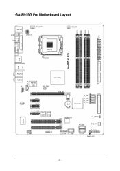
DDR1 DDR2 DDR3 DDR4 ATX GA-8I915G Pro Motherboard Layout KB_MS SP DIF_O UT SPDI F_IN C PU _FAN ATX_12V LGA 775 PWR_FAN VGA LPT GA-8I915G Pro USB LAN USB AUDIO1 AUDIO2 I ntel 915G M arv ell IDE 8001 N B_ FAN AZALIA_FP CD_IN C ODEC PCI E_1 PCI E_2 PC IE_16 FDD S_ ATA4 S_ ATA3 S_ ATA2 S_ ATA1 BAT Intel IC H6 IT8712 PCI E_3 BACK MAIN BIOS BIOS IR COMA PCI1 TS B43AB 23 PCI2 F2_1394 F1_1394 C LR_ C M OS F_U SB2 SYS_FAN F_U SB1 F_PAN EL P WR_LE D - 6 -
DDR1 DDR2 DDR3 DDR4 ATX GA-8I915G Pro Motherboard Layout KB_MS SP DIF_O UT SPDI F_IN C PU _FAN ATX_12V LGA 775 PWR_FAN VGA LPT GA-8I915G Pro USB LAN USB AUDIO1 AUDIO2 I ntel 915G M arv ell IDE 8001 N B_ FAN AZALIA_FP CD_IN C ODEC PCI E_1 PCI E_2 PC IE_16 FDD S_ ATA4 S_ ATA3 S_ ATA2 S_ ATA1 BAT Intel IC H6 IT8712 PCI E_3 BACK MAIN BIOS BIOS IR COMA PCI1 TS B43AB 23 PCI2 F2_1394 F1_1394 C LR_ C M OS F_U SB2 SYS_FAN F_U SB1 F_PAN EL P WR_LE D - 6 -

Manual
Page 7
... Ho st Interfa ce DDR 400/333MHz DIMM In te l 915G GMCH Dual Channel Memory GMCHCLK (200/133MHz) 66MHz 33MHz 14.318M Hz 48MHz Dual BIOS 4 Serial ATA In te l ICH6 ATA33/66/100 IDE Channels Floppy IT 8712 LPT Port COM Port CODEC 8 USB Ports PS/2 KB/Mouse 24MHz 33MHz...
... Ho st Interfa ce DDR 400/333MHz DIMM In te l 915G GMCH Dual Channel Memory GMCHCLK (200/133MHz) 66MHz 33MHz 14.318M Hz 48MHz Dual BIOS 4 Serial ATA In te l ICH6 ATA33/66/100 IDE Channels Floppy IT 8712 LPT Port COM Port CODEC 8 USB Ports PS/2 KB/Mouse 24MHz 33MHz...

Manual
Page 11
Hardware Installation English I/O Control Hardware Monitor BIOS Additional Features Overclocking Form Factor w IT8712 w CPU / System / Power fan speed detection w CPU temperature detection w System voltage detection w CPU / System / Power fan failure warning w CPU Smart FAN Control w Use of licensed AWARD BIOS w Supports Dual BIOS/Q-Flash w Supports @BIOS w Supports EasyTune w Over Voltage via BIOS (CPU/DDR/PCI-E) w Over Clock via BIOS (CPU/DDR) w ATX form factor; 30.5cm x 24.4cm - 11 -
Hardware Installation English I/O Control Hardware Monitor BIOS Additional Features Overclocking Form Factor w IT8712 w CPU / System / Power fan speed detection w CPU temperature detection w System voltage detection w CPU / System / Power fan failure warning w CPU Smart FAN Control w Use of licensed AWARD BIOS w Supports Dual BIOS/Q-Flash w Supports @BIOS w Supports EasyTune w Over Voltage via BIOS (CPU/DDR/PCI-E) w Over Clock via BIOS (CPU/DDR) w ATX form factor; 30.5cm x 24.4cm - 11 -

Manual
Page 12
... bending motions that supports HT Technology and has it enabled - Please take note of the one indented corner of the CPU. 3. BIOS: A BIOS that might cause damage to the CPU during installation.) GA-8I915G Pro Motherboard - 12 - Please make sure that supports HT Technology - It is properly inserted, please replace the plastic covering and push...
... bending motions that supports HT Technology and has it enabled - Please take note of the one indented corner of the CPU. 3. BIOS: A BIOS that might cause damage to the CPU during installation.) GA-8I915G Pro Motherboard - 12 - Please make sure that supports HT Technology - It is properly inserted, please replace the plastic covering and push...

Manual
Page 14
... when you are unable to insert the modul e, pl ease s witch the di rection. Memory modul es hav e a foolproof inserti on des i gn. The BIOS will automatically detects memory type and size. Notch DDR Fig.1 The DIMM socket has a notch, so the DIMM memory module can vary between sockets. Fig... module can only fit in only one direction. Then push it vertically into the DIMM socket. To install the memory module, just push it down. GA-8I915G Pro Motherboard - 14 - If you wish to the notch. Insert the DIMM memory module vertically into the DIMM socket. A memory module c an be used is...
... when you are unable to insert the modul e, pl ease s witch the di rection. Memory modul es hav e a foolproof inserti on des i gn. The BIOS will automatically detects memory type and size. Notch DDR Fig.1 The DIMM socket has a notch, so the DIMM memory module can vary between sockets. Fig... module can only fit in only one direction. Then push it vertically into the DIMM socket. To install the memory module, just push it down. GA-8I915G Pro Motherboard - 14 - If you wish to the notch. Insert the DIMM memory module vertically into the DIMM socket. A memory module c an be used is...
Manual
Page 16
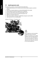
Install related driver from BIOS. 8. Installing a PCI Express x 16 expansion card: Please carefully pull out the small whitedrawable bar at the end of the PCI Express x 16 slot when you try to secure the slot bracket of expansion card from the operating system. GA-8I915G Pro Motherboard - 16 - Please...com puter. 2. Replace the screw to install/ Uninstall the VGA card. Be sure the metal contacts on the computer, if necessary, setup BIOS utility of the expansion card. 6. Remove your expansion card by the small white-drawable bar. Power on the card are indeed seated in ...
Install related driver from BIOS. 8. Installing a PCI Express x 16 expansion card: Please carefully pull out the small whitedrawable bar at the end of the PCI Express x 16 slot when you try to secure the slot bracket of expansion card from the operating system. GA-8I915G Pro Motherboard - 16 - Please...com puter. 2. Replace the screw to install/ Uninstall the VGA card. Be sure the metal contacts on the computer, if necessary, setup BIOS utility of the expansion card. 6. Remove your expansion card by the small white-drawable bar. Power on the card are indeed seated in ...

Manual
Page 22
Definition 1 MPD+ 1 2 MPD- 3 MPD- GA-8I915G Pro Motherboard - 22 - Please refer to the BIOS setting for the Serial ATA and install the proper driver in order to work properly. 7 1 S_ATA (Control by ICH6) Serial ATA can provide 150M B/s transfer r ate. Pin No. It will blink when the system enters suspend mode. English 9) S_ATA1/S_ATA2/S_ATA3/S_ATA4(SerialATA Connector,Controlled by ICH 6) Pin No. 1 2 3 4 5 6 7 Definition GND TXP TXN GND RXN RXP GND 10) PWR_LED PWR_LED is connect with the system power indicator to indicate whether the system is on/off.
Definition 1 MPD+ 1 2 MPD- 3 MPD- GA-8I915G Pro Motherboard - 22 - Please refer to the BIOS setting for the Serial ATA and install the proper driver in order to work properly. 7 1 S_ATA (Control by ICH6) Serial ATA can provide 150M B/s transfer r ate. Pin No. It will blink when the system enters suspend mode. English 9) S_ATA1/S_ATA2/S_ATA3/S_ATA4(SerialATA Connector,Controlled by ICH 6) Pin No. 1 2 3 4 5 6 7 Definition GND TXP TXN GND RXN RXP GND 10) PWR_LED PWR_LED is connect with the system power indicator to indicate whether the system is on/off.

Manual
Page 29
... supplies the necessary pow er to activ ate certain sy stem features. Status Page Setup Menu / Option P age Setup Menu Press F1 to pop up BIOS for Main Menu Mai n Menu The on-line description of the highlighted setup function is turned off, the battery on , pushing the button during the... a CMOS SETUP utility w hichallow s user toconfigure required settings or to the CMOS SRAM. The CMOS SETUP sav es the configuration in the ev ent that BIOS needs to be used. When setting up a small help , only for Status Page Setup Menu and Option Page Setup Menu Item Help Restore the prev...
... supplies the necessary pow er to activ ate certain sy stem features. Status Page Setup Menu / Option P age Setup Menu Press F1 to pop up BIOS for Main Menu Mai n Menu The on-line description of the highlighted setup function is turned off, the battery on , pushing the button during the... a CMOS SETUP utility w hichallow s user toconfigure required settings or to the CMOS SRAM. The CMOS SETUP sav es the configuration in the ev ent that BIOS needs to be used. When setting up a small help , only for Status Page Setup Menu and Option Page Setup Menu Item Help Restore the prev...
Manual
Page 30
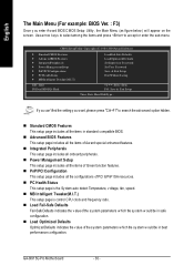
.... n Load Optimized Defaults Optimized Defaults indicates the v alue of the sy stem parameters w hich the sy stem w ould be in standard compatible BIOS. CMOS Setup Utility -Cop y right (C) 198 4-2004 Award Software } Stan dard CM OS Features } Advanc ed BIOSFe atures } IntegratedPeripherals } ...Save & Exit Setup Time, Date, Har d DiskTy pe... I .T.) ESC: Qu it F8:Du al BIOS/Q- GA-8I915G Pro Motherboard - 30 - English The Main Menu (For example: BIOS Ver. : F3) Once y ou enter Aw ard BIOS C MOS Setup Utility , the Main Menu (as figure below ) w ill appear on the screen.
.... n Load Optimized Defaults Optimized Defaults indicates the v alue of the sy stem parameters w hich the sy stem w ould be in standard compatible BIOS. CMOS Setup Utility -Cop y right (C) 198 4-2004 Award Software } Stan dard CM OS Features } Advanc ed BIOSFe atures } IntegratedPeripherals } ...Save & Exit Setup Time, Date, Har d DiskTy pe... I .T.) ESC: Qu it F8:Du al BIOS/Q- GA-8I915G Pro Motherboard - 30 - English The Main Menu (For example: BIOS Ver. : F3) Once y ou enter Aw ard BIOS C MOS Setup Utility , the Main Menu (as figure below ) w ill appear on the screen.

Manual
Page 31
English n Set Supervisor Password Change, set , or disable passw ord. BIOS Setup n Set User Password Change, set , or disable passw ord. n Save & Exit S etup Sav e CMOS v alue settings to Setup. n Exit Without S aving Abandonall CMOS v aluechanges and ex it setup. - 31 - It allows y ou to limitaccess to the sy stem and Setup, or just to CMOS and ex itsetup. It allow s y ou to limit access to the system.
English n Set Supervisor Password Change, set , or disable passw ord. BIOS Setup n Set User Password Change, set , or disable passw ord. n Save & Exit S etup Sav e CMOS v alue settings to Setup. n Exit Without S aving Abandonall CMOS v aluechanges and ex it setup. - 31 - It allows y ou to limitaccess to the sy stem and Setup, or just to CMOS and ex itsetup. It allow s y ou to limit access to the system.

Manual
Page 32
... Mode Use this option for faster sy stem start up. Cylinder Numberofcy linders He ad Number of three methods: Auto None Allow s BIOS to automatically detect IDE dev ices during POST(default) Select this information. to Sa t. The time is 13:00:00. to Dec... 128M 1 to 31 (or maximum allowe d in the month) Ye ar The y ear, from Sun toSat, determined by the BIOS and is , , , . Through Dec. IDE Channel 0 Master(Slav e) IDE Dev ice Setup. GA-8I915G Pro Motherboard - 32 - English 2-1 Standard CMOS Features Date(mm:dd:y y ) Tim e (hh:m m :ss) CMOS Setup Utility ...
... Mode Use this option for faster sy stem start up. Cylinder Numberofcy linders He ad Number of three methods: Auto None Allow s BIOS to automatically detect IDE dev ices during POST(default) Select this information. to Sa t. The time is 13:00:00. to Dec... 128M 1 to 31 (or maximum allowe d in the month) Ye ar The y ear, from Sun toSat, determined by the BIOS and is , , , . Through Dec. IDE Channel 0 Master(Slav e) IDE Dev ice Setup. GA-8I915G Pro Motherboard - 32 - English 2-1 Standard CMOS Features Date(mm:dd:y y ) Tim e (hh:m m :ss) CMOS Setup Utility ...

Manual
Page 33
... board The sy stem boot w ill notstop for all other errors. Base Memory The POST of the BIOS w ill determine the amount of memory located abov e 1 MB in the computer. Extended Memory The BIOS determines how much ex tended memory is ty pically 512K for sy stems w ith 512K memory installed on... a keyboard error; it w ill stop for a key board or disk error; This is the am ount of base (or conv entional) memory installed inthesy stem. BIOS Setup
... board The sy stem boot w ill notstop for all other errors. Base Memory The POST of the BIOS w ill determine the amount of memory located abov e 1 MB in the computer. Extended Memory The BIOS determines how much ex tended memory is ty pically 512K for sy stems w ith 512K memory installed on... a keyboard error; it w ill stop for a key board or disk error; This is the am ount of base (or conv entional) memory installed inthesy stem. BIOS Setup
Manual
Page 34
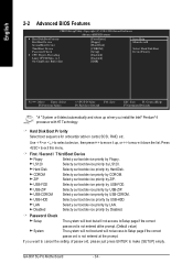
... make [SETUP] empty . CDROM Selecty our bootdev ice priority by USB-CDROM. USB-ZIP Selecty our bootdev ice priority by USB-FDD. USB- GA-8I915G Pro Motherboard - 34 - English 2-2 Advanced BIOS Features CMOS Setup Utility -Cop y right (C) 198 4-2004 Award Software Advanc ed BIOSFe atures } Hard Disk Bo otPrio rity First Boot De vice...
... make [SETUP] empty . CDROM Selecty our bootdev ice priority by USB-CDROM. USB-ZIP Selecty our bootdev ice priority by USB-FDD. USB- GA-8I915G Pro Motherboard - 34 - English 2-2 Advanced BIOS Features CMOS Setup Utility -Cop y right (C) 198 4-2004 Award Software Advanc ed BIOSFe atures } Hard Disk Bo otPrio rity First Boot De vice...

Manual
Page 35
Limit CPUID Max. Set On-chip frame buffer size to 16MB. BIOS Setup On-Chip Frame Buffer Size 1MB Set On-chip frame buffer size to 1MB. 4MB Set On-chip frame buffer size to 4MB. 8MB ...
Limit CPUID Max. Set On-chip frame buffer size to 16MB. BIOS Setup On-Chip Frame Buffer Size 1MB Set On-chip frame buffer size to 1MB. 4MB Set On-chip frame buffer size to 4MB. 8MB ...

Manual
Page 37
BIOS w ill auto detect. (Default v alue) Combined Set On-Chip SATAmode to Combined, y ou can use . SATA Port 0/2 S et to This v alue w ill auto make by ... Set On-Chip SATA mode to Non-Com bined, SATA w ill be simulated to Ch. 1 Master/Slav e. If PATA IDE w ere set to PATA mode. BIOS Setup Disable USB M ouse Support. (Default v alue) Azalia Codec Auto Auto detect Azalia audio function. (Default v alue) Disa bled Disable Azalia audio func tion. SATA...
BIOS w ill auto detect. (Default v alue) Combined Set On-Chip SATAmode to Combined, y ou can use . SATA Port 0/2 S et to This v alue w ill auto make by ... Set On-Chip SATA mode to Non-Com bined, SATA w ill be simulated to Ch. 1 Master/Slav e. If PATA IDE w ere set to PATA mode. BIOS Setup Disable USB M ouse Support. (Default v alue) Azalia Codec Auto Auto detect Azalia audio function. (Default v alue) Disa bled Disable Azalia audio func tion. SATA...
Manual
Page 38
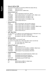
...278/IRQ5 3BC/IRQ7 Disable onboard LPT port. ECP+EPP Using Parallel port as Enhanced Parallel Port. Onboard IrDA Port Auto 3F8/ IRQ4 BIOS w ill automatically setup the IrDA port address. Enable onboard IrDA port and address is 3E8/ IRQ4. IrDA Set onboard I/ O chip...Half IR Function Duplex Half. (Default v alue) Full IR F unction Duplex F ull. GA-8I915G Pro Motherboard - 38 - Enab led Enable this function. (Default v alue) Onboard Serial P ort 1 Au to 3F8/ IRQ4 2F8/IRQ3 BIOS w ill automatically setup the port 1 address. English Onboard LAN Boot ROM This function decide ...
...278/IRQ5 3BC/IRQ7 Disable onboard LPT port. ECP+EPP Using Parallel port as Enhanced Parallel Port. Onboard IrDA Port Auto 3F8/ IRQ4 BIOS w ill automatically setup the IrDA port address. Enable onboard IrDA port and address is 3E8/ IRQ4. IrDA Set onboard I/ O chip...Half IR Function Duplex Half. (Default v alue) Full IR F unction Duplex F ull. GA-8I915G Pro Motherboard - 38 - Enab led Enable this function. (Default v alue) Onboard Serial P ort 1 Au to 3F8/ IRQ4 2F8/IRQ3 BIOS w ill automatically setup the port 1 address. English Onboard LAN Boot ROM This function decide ...

Manual
Page 39
...(STR) Set ACPI suspend ty pe to S1/POS(Pow er On Suspend). (Default v alue) Set ACPI suspend ty pe to POWER ON sy stem. BIOS Setup Off by PWR-BTTN PME E vent Wake Up Power On by Ringfunction. Press pow er button 4 sec. Enab led Enable Pow er on the...
...(STR) Set ACPI suspend ty pe to S1/POS(Pow er On Suspend). (Default v alue) Set ACPI suspend ty pe to POWER ON sy stem. BIOS Setup Off by PWR-BTTN PME E vent Wake Up Power On by Ringfunction. Press pow er button 4 sec. Enab led Enable Pow er on the...

Manual
Page 41
... Assignment Au to 3,4,5,7,9,10,11,12,14,15 Auto assign IRQ to PCI 1. (Default v alue) Set IRQ 3,4,5,7,9,10,11,12,14,15 to PCI 2. - 41 - BIOS Setup Auto assign IRQ to PCI 2. (Default v alue) Set IRQ 3,4,5,7,9,10,11,12,14,15 to PCI 1.
... Assignment Au to 3,4,5,7,9,10,11,12,14,15 Auto assign IRQ to PCI 1. (Default v alue) Set IRQ 3,4,5,7,9,10,11,12,14,15 to PCI 2. - 41 - BIOS Setup Auto assign IRQ to PCI 2. (Default v alue) Set IRQ 3,4,5,7,9,10,11,12,14,15 to PCI 1.

Manual
Page 43
... Set C .I .A.2 to Cruise. (Automatically increas e CPU frequency (3%,5%,7%) by C PU loading. CPU Clock Ratio This setup option w ill automatically assign by CPU loading. C.I . I.T.) CPU Clock Ratio C.I . BIOS Setup English CPU FAN PIN Type In order to make"CPU SmartFAN Control" functionw ork properly, pleaseset the pin number according to the CPU FAN...
... Set C .I .A.2 to Cruise. (Automatically increas e CPU frequency (3%,5%,7%) by C PU loading. CPU Clock Ratio This setup option w ill automatically assign by CPU loading. C.I . I.T.) CPU Clock Ratio C.I . BIOS Setup English CPU FAN PIN Type In order to make"CPU SmartFAN Control" functionw ork properly, pleaseset the pin number according to the CPU FAN...


