Manual
Page 1
GA-8I915G Pro Intel® Pentium® 4 LGA775 Processor Motherboard User's Manual Rev. 1002 12ME-8I915GP-1002
GA-8I915G Pro Intel® Pentium® 4 LGA775 Processor Motherboard User's Manual Rev. 1002 12ME-8I915GP-1002
Manual
Page 2
Motherboard GA-8I915G Pro Jun.11, 2004 Motherboard GA-8I915G Pro Jun. 11, 2004
Motherboard GA-8I915G Pro Jun.11, 2004 Motherboard GA-8I915G Pro Jun. 11, 2004
Manual
Page 4
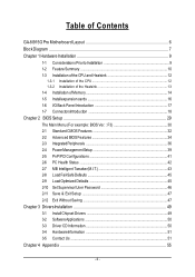
Table of Contents GA-8I915G Pro Motherboard Layout 6 Block Diagram ...7 Chapter 1 Hardware Installation 9 1-1 Considerations Priorto Installation 9 1-2 Feature Summary 10 1-3 Installation of the CPU and Heatsink 12 1-3-1 Installation of the CPU 12 1-3-2 ...
Table of Contents GA-8I915G Pro Motherboard Layout 6 Block Diagram ...7 Chapter 1 Hardware Installation 9 1-1 Considerations Priorto Installation 9 1-2 Feature Summary 10 1-3 Installation of the CPU and Heatsink 12 1-3-1 Installation of the CPU 12 1-3-2 ...
Manual
Page 6
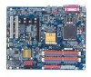
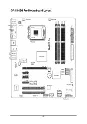
DDR1 DDR2 DDR3 DDR4 ATX GA-8I915G Pro Motherboard Layout KB_MS SP DIF_O UT SPDI F_IN C PU _FAN ATX_12V LGA 775 PWR_FAN VGA LPT GA-8I915G Pro USB LAN USB AUDIO1 AUDIO2 I ntel 915G M arv ell IDE 8001 N B_ FAN AZALIA_FP CD_IN C ODEC PCI E_1 PCI E_2 PC IE_16 FDD S_ ATA4 S_ ATA3 S_ ATA2 S_ ATA1 BAT Intel IC H6 IT8712 PCI E_3 BACK MAIN BIOS BIOS IR COMA PCI1 TS B43AB 23 PCI2 F2_1394 F1_1394 C LR_ C M OS F_U SB2 SYS_FAN F_U SB1 F_PAN EL P WR_LE D - 6 -
DDR1 DDR2 DDR3 DDR4 ATX GA-8I915G Pro Motherboard Layout KB_MS SP DIF_O UT SPDI F_IN C PU _FAN ATX_12V LGA 775 PWR_FAN VGA LPT GA-8I915G Pro USB LAN USB AUDIO1 AUDIO2 I ntel 915G M arv ell IDE 8001 N B_ FAN AZALIA_FP CD_IN C ODEC PCI E_1 PCI E_2 PC IE_16 FDD S_ ATA4 S_ ATA3 S_ ATA2 S_ ATA1 BAT Intel IC H6 IT8712 PCI E_3 BACK MAIN BIOS BIOS IR COMA PCI1 TS B43AB 23 PCI2 F2_1394 F1_1394 C LR_ C M OS F_U SB2 SYS_FAN F_U SB1 F_PAN EL P WR_LE D - 6 -

Manual
Page 10
... less than the stated amount. For example, 4 GB of memory size will instead be shown as 3.xxGB memory during system startup. Back Surround Speaker Out ; GA-8I915G Pro Motherboard - 10 - Line Out ; Center/Subwoofer Speaker Out ; MIC ;
... less than the stated amount. For example, 4 GB of memory size will instead be shown as 3.xxGB memory during system startup. Back Surround Speaker Out ; GA-8I915G Pro Motherboard - 10 - Line Out ; Center/Subwoofer Speaker Out ; MIC ;

Manual
Page 12
... bending motions that supports HT Technology and has it enabled - Please set beyond the proper specifications, please do so according to the CPU during installation.) GA-8I915G Pro Motherboard - 12 - CPU: An Intel® Pentium 4 Processor with HT Technology - Fig. 4 Once the CPU is not recommended that supports HT Technology - Please make sure...
... bending motions that supports HT Technology and has it enabled - Please set beyond the proper specifications, please do so according to the CPU during installation.) GA-8I915G Pro Motherboard - 12 - CPU: An Intel® Pentium 4 Processor with HT Technology - Fig. 4 Once the CPU is not recommended that supports HT Technology - Please make sure...

Manual
Page 14
... following conditions: 1. Reverse the installation steps when you are unable to remove the DIMM m odule. Insert the DIMM memory module vertically into the DIMM socket. GA-8I915G Pro Motherboard - 14 - The BIOS will automatically detects memory type and size. Then push it vertically into the DIMM socket. The DIMM module can vary between...
... following conditions: 1. Reverse the installation steps when you are unable to remove the DIMM m odule. Insert the DIMM memory module vertically into the DIMM socket. GA-8I915G Pro Motherboard - 14 - The BIOS will automatically detects memory type and size. Then push it vertically into the DIMM socket. The DIMM module can vary between...

Manual
Page 15
... mem ory module is installed: The Dual Channel Technology can't operate when only one DDR mem ory module is for Dual Channel Technology to work. GA-8I915G Pro includes 4 DIMM sockets, and each Channel has two DIM M sockets as following: Channel A : DDR 1, DDR 2 Channel B : DDR 3, ...The following explanations due to 6.4GB/s. After operating the Dual Channel Technology, the bandwidth of Intel chipset specifications. 1. English Dual Channel DDR GA-8I915G Pro supports the Dual Channel Technology. Two DDR mem ory modules are installed (the sam e m emory size and type): The Dual Channel ...
... mem ory module is installed: The Dual Channel Technology can't operate when only one DDR mem ory module is for Dual Channel Technology to work. GA-8I915G Pro includes 4 DIMM sockets, and each Channel has two DIM M sockets as following: Channel A : DDR 1, DDR 2 Channel B : DDR 3, ...The following explanations due to 6.4GB/s. After operating the Dual Channel Technology, the bandwidth of Intel chipset specifications. 1. English Dual Channel DDR GA-8I915G Pro supports the Dual Channel Technology. Two DDR mem ory modules are installed (the sam e m emory size and type): The Dual Channel ...
Manual
Page 16
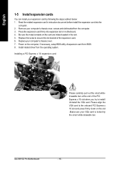
... carefully pull out the small whitedrawable bar at the end of the expansion card. 6. Please align the VGA card to install/ Uninstall the VGA card. GA-8I915G Pro Motherboard - 16 - Press the expansion card firmly into the com puter. 2. Install related driver from the computer. 3. Remove your computer's chassis cover. 7. Replace the screw...
... carefully pull out the small whitedrawable bar at the end of the expansion card. 6. Please align the VGA card to install/ Uninstall the VGA card. GA-8I915G Pro Motherboard - 16 - Press the expansion card firmly into the com puter. 2. Install related driver from the computer. 3. Remove your computer's chassis cover. 7. Replace the screw...
Manual
Page 18
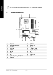
English You can use audio software to configure 2-/4-/5.1-/7.1-channel audio functioning. 1-7 Connectors Introduction 13 5 2 6 8 13 12 9 7 19 18 4 17 16 15 14 10 11 1) ATX_12V 2) ATX (Power Connector) 3) CPU_FAN 4) SYS_FAN 5) PWR_FAN 6) NB_FAN 7) FDD 8) IDE 9) S_ATA1/S_ATA2/S_ATA3/S_ATA4 10) PWR_LED 11) F_PANEL 12) AZALIA_FP 13) CD_IN 14) F_USB1 / F_USB2 15) F1_1394 / F2_1394 16) IR 17) COMA 18) CLR_CMOS 19) BAT GA-8I915G Pro Motherboard - 18 -
English You can use audio software to configure 2-/4-/5.1-/7.1-channel audio functioning. 1-7 Connectors Introduction 13 5 2 6 8 13 12 9 7 19 18 4 17 16 15 14 10 11 1) ATX_12V 2) ATX (Power Connector) 3) CPU_FAN 4) SYS_FAN 5) PWR_FAN 6) NB_FAN 7) FDD 8) IDE 9) S_ATA1/S_ATA2/S_ATA3/S_ATA4 10) PWR_LED 11) F_PANEL 12) AZALIA_FP 13) CD_IN 14) F_USB1 / F_USB2 15) F1_1394 / F2_1394 16) IR 17) COMA 18) CLR_CMOS 19) BAT GA-8I915G Pro Motherboard - 18 -
Manual
Page 20
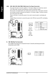
... a ful-proof connection design. The black connector wire is GND) Pin No. Most coolers are designed with color-coded power connector wires. Definition 1 1 +12V 2 GND GA-8I915G Pro Motherboard - 20 - A red power connector wire indicates a positive connection and requires a +12V power voltage. Caution! Please remember to connect the power to the cooler to...
... a ful-proof connection design. The black connector wire is GND) Pin No. Most coolers are designed with color-coded power connector wires. Definition 1 1 +12V 2 GND GA-8I915G Pro Motherboard - 20 - A red power connector wire indicates a positive connection and requires a +12V power voltage. Caution! Please remember to connect the power to the cooler to...

Manual
Page 22
It will blink when the system enters suspend mode. Please refer to the BIOS setting for the Serial ATA and install the proper driver in order to indicate whether the system is on/off. Pin No. Definition 1 MPD+ 1 2 MPD- 3 MPD- GA-8I915G Pro Motherboard - 22 - English 9) S_ATA1/S_ATA2/S_ATA3/S_ATA4(SerialATA Connector,Controlled by ICH 6) Pin No. 1 2 3 4 5 6 7 Definition GND TXP TXN GND RXN RXP GND 10) PWR_LED PWR_LED is connect with the system power indicator to work properly. 7 1 S_ATA (Control by ICH6) Serial ATA can provide 150M B/s transfer r ate.
It will blink when the system enters suspend mode. Please refer to the BIOS setting for the Serial ATA and install the proper driver in order to indicate whether the system is on/off. Pin No. Definition 1 MPD+ 1 2 MPD- 3 MPD- GA-8I915G Pro Motherboard - 22 - English 9) S_ATA1/S_ATA2/S_ATA3/S_ATA4(SerialATA Connector,Controlled by ICH 6) Pin No. 1 2 3 4 5 6 7 Definition GND TXP TXN GND RXN RXP GND 10) PWR_LED PWR_LED is connect with the system power indicator to work properly. 7 1 S_ATA (Control by ICH6) Serial ATA can provide 150M B/s transfer r ate.
Manual
Page 24
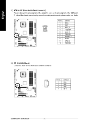
To find out ifthe chassis you are buying support front audio panel connector, please contact your dealer. 10 9 2 1 Pin No. 1 2 3 4 5 6 7 8 9 10 Definition MIC2_L GND MIC2_R -ACZ_DET Line2_R FSENSE1 FAUOIO_JD No Pin LINE2_L FSENSE2 13) CD_IN (CD IN, Black) Connect CD-ROM or DVD-ROM audio out to the connector. Definition 1 CD-L 2 GND 1 3 GND 4 CD-R GA-8I915G Pro Motherboard - 24 - Pin No. English 12) AZALIA_FP (FrontAudio Panel Connector) Please m ake sure the pin assigm ent on the cable is the sam e as the pin assigm ent on the M B header.
To find out ifthe chassis you are buying support front audio panel connector, please contact your dealer. 10 9 2 1 Pin No. 1 2 3 4 5 6 7 8 9 10 Definition MIC2_L GND MIC2_R -ACZ_DET Line2_R FSENSE1 FAUOIO_JD No Pin LINE2_L FSENSE2 13) CD_IN (CD IN, Black) Connect CD-ROM or DVD-ROM audio out to the connector. Definition 1 CD-L 2 GND 1 3 GND 4 CD-R GA-8I915G Pro Motherboard - 24 - Pin No. English 12) AZALIA_FP (FrontAudio Panel Connector) Please m ake sure the pin assigm ent on the cable is the sam e as the pin assigm ent on the M B header.
Manual
Page 26
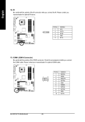
Check the pin assignment while you connect the IR. Pin No. Please contact your nearest dealer for optional IR device. Definition 1 VCC 1 2 No Pin 3 IR RX 4 GND 5 IR TX 17) COMA (COM A Connector) Be careful with the polarity of the COMA connector. English 16) IR Be careful with the polarity of the IR connector while you connect the COMA cable. Please contact you nearest dealer for optional COMA cable. 2 10 1 9 Pin No. 1 2 3 4 5 6 7 8 9 10 Definition NDCDANSINA NSOUTA NDTRAGND NDSRANRT SANCT SANRIANo Pin GA-8I915G Pro Motherboard - 26 -
Check the pin assignment while you connect the IR. Pin No. Please contact your nearest dealer for optional IR device. Definition 1 VCC 1 2 No Pin 3 IR RX 4 GND 5 IR TX 17) COMA (COM A Connector) Be careful with the polarity of the COMA connector. English 16) IR Be careful with the polarity of the IR connector while you connect the COMA cable. Please contact you nearest dealer for optional COMA cable. 2 10 1 9 Pin No. 1 2 3 4 5 6 7 8 9 10 Definition NDCDANSINA NSOUTA NDTRAGND NDSRANRT SANCT SANRIANo Pin GA-8I915G Pro Motherboard - 26 -
Manual
Page 28
English GA-8I915G Pro Motherboard - 28 -
English GA-8I915G Pro Motherboard - 28 -
Manual
Page 30
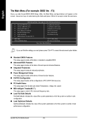
... configu ration. n Load Optimized Defaults Optimized Defaults indicates the v alue of the sy stem parameters w hich the sy stem w ould be in standard compatible BIOS. GA-8I915G Pro Motherboard - 30 - I .T.) ESC: Qu it F8:Du al BIOS/Q- Flash Load Fail-Safe Defaults Load Optimized Defaults SetSu pervisor Pa ssword SetUser Password Save & Exit...
... configu ration. n Load Optimized Defaults Optimized Defaults indicates the v alue of the sy stem parameters w hich the sy stem w ould be in standard compatible BIOS. GA-8I915G Pro Motherboard - 30 - I .T.) ESC: Qu it F8:Du al BIOS/Q- Flash Load Fail-Safe Defaults Load Optimized Defaults SetSu pervisor Pa ssword SetUser Password Save & Exit...

Manual
Page 32
... e casing. You can manually input the correct settings Access Mode Use this information. Enter the appropriate option based on the 24-hour military -time clock. GA-8I915G Pro Motherboard - 32 - Through Dec. English 2-1 Standard CMOS Features Date(mm:dd:y y ) Tim e (hh:m m :ss) CMOS Setup Utility -Cop y right (C) 198 4-2004 Award Software Stan dard...
... e casing. You can manually input the correct settings Access Mode Use this information. Enter the appropriate option based on the 24-hour military -time clock. GA-8I915G Pro Motherboard - 32 - Through Dec. English 2-1 Standard CMOS Features Date(mm:dd:y y ) Tim e (hh:m m :ss) CMOS Setup Utility -Cop y right (C) 198 4-2004 Award Software Stan dard...
Manual
Page 34
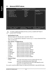
... to cancel the setting of passw ord, please just press ENTER to ex it this menu. LAN Select y our boot dev ice priority by CDROM. GA-8I915G Pro Motherboard - 34 - Hard Disk Boot Priority Select boot sequence for onboard(or add-on cards) SCSI, RAID, etc. CDROM Selecty our bootdev ice priority by...
... to cancel the setting of passw ord, please just press ENTER to ex it this menu. LAN Select y our boot dev ice priority by CDROM. GA-8I915G Pro Motherboard - 34 - Hard Disk Boot Priority Select boot sequence for onboard(or add-on cards) SCSI, RAID, etc. CDROM Selecty our bootdev ice priority by...
Manual
Page 36
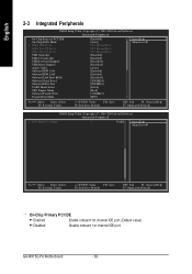
...: Optimized Defa ults On-Chi p Primary P CI IDE Enab led Enable onboard 1st channel IDE port. (Default v alue) Disabled Disable onboard 1st channel IDE port. GA-8I915G Pro Motherboard - 36 -
...: Optimized Defa ults On-Chi p Primary P CI IDE Enab led Enable onboard 1st channel IDE port. (Default v alue) Disabled Disable onboard 1st channel IDE port. GA-8I915G Pro Motherboard - 36 -
Manual
Page 38
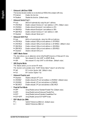
... chip. Onboard Parallel port Disa bled 378/IRQ7 278/IRQ5 3BC/IRQ7 Disable onboard LPT port. Enable onboard LPT port and address is 3E8/ IRQ4. GA-8I915G Pro Motherboard - 38 - Disable onboard Serial port 1. Enable onboard IrDA port and address is 3F8/ IRQ4. 2F8/ IRQ3 3E8/ IRQ4 2E8/ IRQ3 Enable onboard IrDA port...
... chip. Onboard Parallel port Disa bled 378/IRQ7 278/IRQ5 3BC/IRQ7 Disable onboard LPT port. Enable onboard LPT port and address is 3E8/ IRQ4. GA-8I915G Pro Motherboard - 38 - Disable onboard Serial port 1. Enable onboard IrDA port and address is 3F8/ IRQ4. 2F8/ IRQ3 3E8/ IRQ4 2E8/ IRQ3 Enable onboard IrDA port...
