Manual
Page 4
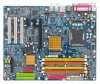
... Setup Utility-Copyright (C) 1984-2004 Award Software Advanced BIOS Features ` Hard Disk Boot Priority First Boot Device Second Boot Device Third Boot Device Password Check CPU Hyper-Threading Limit CPUID Max. Bootable Add-in Cards Item Help Menu Level `` Use or to select a device, then press to move it down the...
... Setup Utility-Copyright (C) 1984-2004 Award Software Advanced BIOS Features ` Hard Disk Boot Priority First Boot Device Second Boot Device Third Boot Device Password Check CPU Hyper-Threading Limit CPUID Max. Bootable Add-in Cards Item Help Menu Level `` Use or to select a device, then press to move it down the...
Manual
Page 4
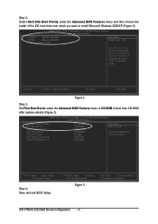
Table of Contents GA-8I915G Duo Motherboard Layout 6 Block Diagram ...7 Chapter 1 Hardware Installation 9 1-1 Considerations Prior to Installation 9 1-2 Feature Summary 10 1-3 Installation of the CPU and Heatsink 12 1-3-1 Installation of the CPU 12 1-3-2 Installation of the Heatsink 13 1-4 Installation of Memory 14 1-5 Installation of Expansion Cards 16 1-6 I/O Back Panel Introduction 17 1-7 Connectors Introduction 18 Chapter 2 BIOS Setup...
Table of Contents GA-8I915G Duo Motherboard Layout 6 Block Diagram ...7 Chapter 1 Hardware Installation 9 1-1 Considerations Prior to Installation 9 1-2 Feature Summary 10 1-3 Installation of the CPU and Heatsink 12 1-3-1 Installation of the CPU 12 1-3-2 Installation of the Heatsink 13 1-4 Installation of Memory 14 1-5 Installation of Expansion Cards 16 1-6 I/O Back Panel Introduction 17 1-7 Connectors Introduction 18 Chapter 2 BIOS Setup...
Manual
Page 9
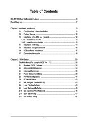
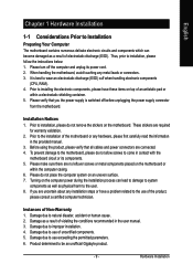
... user manual. 3. Instances of uncertified components. 5. Hardware Installation These stickers are connected. 4. Product determined to wear an electrostatic discharge (ESD) cuff when handling electronic components (CPU, RAM). 4. Please make sure there are uncertain about any metal leads or connectors. 3. Damage as physical harm to system components as well as a result of... instructions below: 1. Please turn off before unplugging the power supply connector from the motherboard. If you the power supply is best to be an unofficial Gigabyte product. - 9 -
... user manual. 3. Instances of uncertified components. 5. Hardware Installation These stickers are connected. 4. Product determined to wear an electrostatic discharge (ESD) cuff when handling electronic components (CPU, RAM). 4. Please make sure there are uncertain about any metal leads or connectors. 3. Damage as physical harm to system components as well as a result of... instructions below: 1. Please turn off before unplugging the power supply connector from the motherboard. If you the power supply is best to be an unofficial Gigabyte product. - 9 -
Manual
Page 10
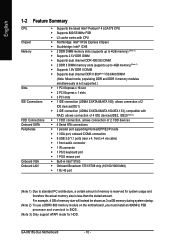
... IDE Connections FDD Connections Onboard SATA Peripherals Onboard VGA Onboard LAN Š Supports the latest Intel® Pentium® 4 LGA775 CPU Š Supports 800/533MHz FSB Š L2 cache varies with CPU Š Northbridge: Intel® 915G Express Chipset Š Southbridge: Intel® ICH6 Š 2 DDR DIMM memory slots (supports up to... channel DDR II 600(Note 2)/533/400 DIMM (Note: Mixed mode, populating DDR and DDR II memory modules simultaneously is less than the stated amount. GA-8I915G Duo Motherboard - 10 - For example, 4 GB of memory is reserved for HDD.
... IDE Connections FDD Connections Onboard SATA Peripherals Onboard VGA Onboard LAN Š Supports the latest Intel® Pentium® 4 LGA775 CPU Š Supports 800/533MHz FSB Š L2 cache varies with CPU Š Northbridge: Intel® 915G Express Chipset Š Southbridge: Intel® ICH6 Š 2 DDR DIMM memory slots (supports up to... channel DDR II 600(Note 2)/533/400 DIMM (Note: Mixed mode, populating DDR and DDR II memory modules simultaneously is less than the stated amount. GA-8I915G Duo Motherboard - 10 - For example, 4 GB of memory is reserved for HDD.
Manual
Page 11
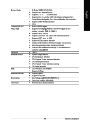
...in controller onboard BIOS Š IT8712 Š System voltage detection Š CPU temperature detection Š CPU / System / Power fan speed detection Š CPU warning temperature Š CPU / System / Power fan failure warning Š CPU smart fan control Š Use of licensed AWARD BIOS Š Supports Q-...Flash Š Supports @BIOS Š Supports EasyTune Š Over Voltage via BIOS (CPU/DDR/PCI-E) Š Over Clock via BIOS (CPU/DDR) Š ATX form factor; 30.5cm x 24.4cm - 11 - Center/Subwoofer Speaker Out ; Hardware Installation Line...
...in controller onboard BIOS Š IT8712 Š System voltage detection Š CPU temperature detection Š CPU / System / Power fan speed detection Š CPU warning temperature Š CPU / System / Power fan failure warning Š CPU smart fan control Š Use of licensed AWARD BIOS Š Supports Q-...Flash Š Supports @BIOS Š Supports EasyTune Š Over Voltage via BIOS (CPU/DDR/PCI-E) Š Over Clock via BIOS (CPU/DDR) Š ATX form factor; 30.5cm x 24.4cm - 11 - Center/Subwoofer Speaker Out ; Hardware Installation Line...
Manual
Page 12
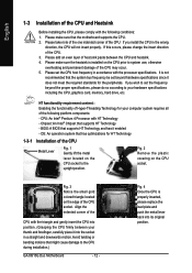
...required standards for your computer system requires all of the CPU with HT Technology - Fig. 2 Remove the plastic covering on the CPU prior to the CPU during installation.) GA-8I915G Duo Motherboard - 12 - Fig. 4 Once the CPU is properly inserted, please replace the load plate and ...push the metal lever back into position. (Grasping the CPU firmly between the CPU and heatsink. 4. If this occurs...
...required standards for your computer system requires all of the CPU with HT Technology - Fig. 2 Remove the plastic covering on the CPU prior to the CPU during installation.) GA-8I915G Duo Motherboard - 12 - Fig. 4 Once the CPU is properly inserted, please replace the load plate and ...push the metal lever back into position. (Grasping the CPU firmly between the CPU and heatsink. 4. If this occurs...
Manual
Page 13
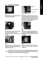
...to remove the heatsink, on the contrary, is to the heatsink installation section of the user manual) Fig. 5 Please check the back of the installed CPU. If the push pin is inserted as a result of hardening of arrow sign on the male push pin doesn't face inwards before installation. (This ...instruction is only for Intel boxed fan) Fig. 3 Place the heatsink atop the CPU and make sure the Male and Female push pin are joined closely. (for heat dissipation or using extreme care when removing the heatsink. - 13 - ...
...to remove the heatsink, on the contrary, is to the heatsink installation section of the user manual) Fig. 5 Please check the back of the installed CPU. If the push pin is inserted as a result of hardening of arrow sign on the male push pin doesn't face inwards before installation. (This ...instruction is only for Intel boxed fan) Fig. 3 Place the heatsink atop the CPU and make sure the Male and Female push pin are joined closely. (for heat dissipation or using extreme care when removing the heatsink. - 13 - ...
Manual
Page 19
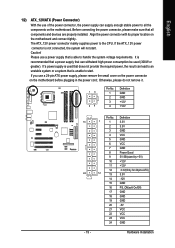
... will not start . English 1/2) ATX_12V/ATX (Power Connector) With the use of the power connector, the power supply can supply enough stable power to the CPU. Before connecting the power connector, please make sure that is able to start . Pin No.
... will not start . English 1/2) ATX_12V/ATX (Power Connector) With the use of the power connector, the power supply can supply enough stable power to the CPU. Before connecting the power connector, please make sure that is able to start . Pin No.
Manual
Page 20
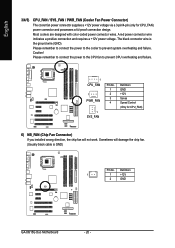
Please remember to connect the power to the CPU fan to prevent system overheating and failure. Most coolers are designed with color-coded power connector wires. Caution! Definition 1 1 +12V 2 GND GA-8I915G Duo Motherboard - 20 - A red power connector wire indicates a positive connection and requires a +12V power ... (Usually black cable is the ground wire (GND). Sometimes will not work. Please remember to connect the power to the cooler to prevent CPU overheating and failure. 1 CPU_FAN 1 PWR_FAN 1 SYS_FAN Pin No. 1 2 3 4 Definition GND +12V Sense Speed Control (Only for ...
Please remember to connect the power to the CPU fan to prevent system overheating and failure. Most coolers are designed with color-coded power connector wires. Caution! Definition 1 1 +12V 2 GND GA-8I915G Duo Motherboard - 20 - A red power connector wire indicates a positive connection and requires a +12V power ... (Usually black cable is the ground wire (GND). Sometimes will not work. Please remember to connect the power to the cooler to prevent CPU overheating and failure. 1 CPU_FAN 1 PWR_FAN 1 SYS_FAN Pin No. 1 2 3 4 Definition GND +12V Sense Speed Control (Only for ...
Manual
Page 30
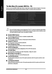
...Please Load Optimized Defaults in the BIOS when somehow the system works not stable as figure below) will appear on the screen. GA-8I915G Duo Motherboard - 30 - This action makes the system reset to accept or enter the sub-menu. Use arrow keys to select ...Advanced BIOS Features ` Integrated Peripherals ` Power Management Setup ` PnP/PCI Configurations ` PC Health Status ` MB Intelligent Tweaker(M.I .T.) This setup page is control CPU clock and frequency ratio. „ Load Fail-Safe Defaults Fail-Safe Defaults indicates the value of the system parameters which the system would be in...
...Please Load Optimized Defaults in the BIOS when somehow the system works not stable as figure below) will appear on the screen. GA-8I915G Duo Motherboard - 30 - This action makes the system reset to accept or enter the sub-menu. Use arrow keys to select ...Advanced BIOS Features ` Integrated Peripherals ` Power Management Setup ` PnP/PCI Configurations ` PC Health Status ` MB Intelligent Tweaker(M.I .T.) This setup page is control CPU clock and frequency ratio. „ Load Fail-Safe Defaults Fail-Safe Defaults indicates the value of the system parameters which the system would be in...

Manual
Page 33
... drive B that has been installed in the computer. BIOS Setup English Drive A / Drive B The category identifies the types of memory located above 1 MB in the CPU's memory address map. All Errors Whenever the BIOS detects a non-fatal error the system will not stop for all other errors. (Default value) All, But...
... drive B that has been installed in the computer. BIOS Setup English Drive A / Drive B The category identifies the types of memory located above 1 MB in the CPU's memory address map. All Errors Whenever the BIOS detects a non-fatal error the system will not stop for all other errors. (Default value) All, But...

Manual
Page 34
...to move it down the list. Hard Disk Boot Priority Select boot sequence for onboard(or add-on cards) SCSI, RAID, etc. GA-8I915G Duo Motherboard - 34 - English 2-2 Advanced BIOS Features CMOS Setup Utility-Copyright (C) 1984-2004 Award Software Advanced BIOS Features ` Hard Disk ...Boot Device Floppy Select your boot device priority by Disabled. (Note) This item will show up , or to 3 No-Execute Memory Protect (Note) CPU Enhanced Halt (C1E) (Note) CPU Thermal Monitor 2(TM2) (Note) On-Chip Frame Buffer Size [Press Enter] [Floppy] [Hard Disk] [CDROM] [Setup] [Enabled] [Disabled]...
...to move it down the list. Hard Disk Boot Priority Select boot sequence for onboard(or add-on cards) SCSI, RAID, etc. GA-8I915G Duo Motherboard - 34 - English 2-2 Advanced BIOS Features CMOS Setup Utility-Copyright (C) 1984-2004 Award Software Advanced BIOS Features ` Hard Disk ...Boot Device Floppy Select your boot device priority by Disabled. (Note) This item will show up , or to 3 No-Execute Memory Protect (Note) CPU Enhanced Halt (C1E) (Note) CPU Thermal Monitor 2(TM2) (Note) On-Chip Frame Buffer Size [Press Enter] [Floppy] [Hard Disk] [CDROM] [Setup] [Enabled] [Disabled]...

Manual
Page 35
... windows XP. (Default value) No-Execute Memory Protect (Note) Enabled Disabled Enables No-Execute Memory Protect function. CPU Hyper-Threading Enabled Enables CPU Hyper Threading Feature. Please note that this function. - 35 - to 3 Enabled Disabled Limit CPUID Maximum value ... for operating system with multi processors mode supported. (Default value) Disables CPU Hyper Threading. Disables CPU Enhanced Halt (C1E) function. (Default value) CPU Thermal Monitor 2 (TM2) (Note) Enabled Disabled Enable CPU Thermal Monitor 2 (TM2) function. If you install a processor which ...
... windows XP. (Default value) No-Execute Memory Protect (Note) Enabled Disabled Enables No-Execute Memory Protect function. CPU Hyper-Threading Enabled Enables CPU Hyper Threading Feature. Please note that this function. - 35 - to 3 Enabled Disabled Limit CPUID Maximum value ... for operating system with multi processors mode supported. (Default value) Disables CPU Hyper Threading. Disables CPU Enhanced Halt (C1E) function. (Default value) CPU Thermal Monitor 2 (TM2) (Note) Enabled Disabled Enable CPU Thermal Monitor 2 (TM2) function. If you install a processor which ...

Manual
Page 42
... CPU Temperature Detect CPU temperature automatically. CPU Warning Temperature 60oC / 140oF Monitor CPU temperature at 60oC / 140oF. 70oC / 158oF Monitor CPU temperature at 70oC / 158oF. 80oC / 176oF Monitor CPU temperature at 80oC / 176oF. 90oC / 194oF Disabled Monitor CPU temperature at full speed. GA-8I915G Duo Motherboard - 42 - When the CPU temperature is more than 41 degree and less than 65 degree. CPU...
... CPU Temperature Detect CPU temperature automatically. CPU Warning Temperature 60oC / 140oF Monitor CPU temperature at 60oC / 140oF. 70oC / 158oF Monitor CPU temperature at 70oC / 158oF. 80oC / 176oF Monitor CPU temperature at 80oC / 176oF. 90oC / 194oF Disabled Monitor CPU temperature at full speed. GA-8I915G Duo Motherboard - 42 - When the CPU temperature is more than 41 degree and less than 65 degree. CPU...
Manual
Page 43
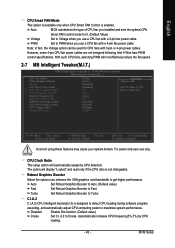
...CMOS Setup Utility-Copyright (C) 1984-2004 Award Software MB Intelligent Tweaker(M.I.T.) CPU Clock Ratio Robust Graphics Booster C.I.A.2 CPU Host Clock Control x CPU Host Frequency (Mhz) x PCI-E Frequency to PWM when you use a CPU fan with 3-pin or 4-pin power cables. Turbo Set Robust Graphics... will display "Locked" and read only if the CPU ratio is designed to detect CPU loading during software program executing, and automatically adjust CPU computing power to Cruise. (Automatically increase CPU frequency(5%,7%) by CPU detection. Robust Graphics Booster Select the options can be...
...CMOS Setup Utility-Copyright (C) 1984-2004 Award Software MB Intelligent Tweaker(M.I.T.) CPU Clock Ratio Robust Graphics Booster C.I.A.2 CPU Host Clock Control x CPU Host Frequency (Mhz) x PCI-E Frequency to PWM when you use a CPU fan with 3-pin or 4-pin power cables. Turbo Set Robust Graphics... will display "Locked" and read only if the CPU ratio is designed to detect CPU loading during software program executing, and automatically adjust CPU computing power to Cruise. (Automatically increase CPU frequency(5%,7%) by CPU detection. Robust Graphics Booster Select the options can be...

Manual
Page 44
...and cannot restart, please wait 20secs. Incorrect using it may make system can't boot, clear CMOS to Sports. (Automatically increase CPU frequency(7%,9%) by CPU loading. Turbo Set C.I.A.2 to 600MHz. If you use a DDRII 600 memory module on the motherboard, you must install an ... frequency by DRAM SPD data. (Default value) Memory Frequency (Mhz) The values depend on system components. GA-8I915G Duo Motherboard - 44 - CPU Host Clock Control Please note that by CPU loading. If you use only! Auto Set Memory frequency by DRAM SPD data. (Default value) for FSB...
...and cannot restart, please wait 20secs. Incorrect using it may make system can't boot, clear CMOS to Sports. (Automatically increase CPU frequency(7%,9%) by CPU loading. Turbo Set C.I.A.2 to 600MHz. If you use a DDRII 600 memory module on the motherboard, you must install an ... frequency by DRAM SPD data. (Default value) Memory Frequency (Mhz) The values depend on system components. GA-8I915G Duo Motherboard - 44 - CPU Host Clock Control Please note that by CPU loading. If you use only! Auto Set Memory frequency by DRAM SPD data. (Default value) for FSB...

Manual
Page 45
...+0.2V Set PCI-E OverVoltage Control to Normal. (Default value) Set PCI-E OverVoltage Control to +0.3V. CPU Voltage Control Supports adjustable CPU Vcore from 0.8375V to 1.6000V. (Default value: Normal) Warning: CPU may cause your CPU Vcore Voltage. 2-8 Load Fail-Safe Defaults CMOS Setup Utility-Copyright (C) 1984-2004 Award Software ` Standard...Set Supervisor Password ` Power Management Setup Set User Password ` PnP/PCI Configurations Load Fail-Safe DefaultsS(aYv/eN&)? BIOS Setup Normal CPU Vcore Display your system broken. English Incorrect using it may be damaged or reduce...
...+0.2V Set PCI-E OverVoltage Control to Normal. (Default value) Set PCI-E OverVoltage Control to +0.3V. CPU Voltage Control Supports adjustable CPU Vcore from 0.8375V to 1.6000V. (Default value: Normal) Warning: CPU may cause your CPU Vcore Voltage. 2-8 Load Fail-Safe Defaults CMOS Setup Utility-Copyright (C) 1984-2004 Award Software ` Standard...Set Supervisor Password ` Power Management Setup Set User Password ` PnP/PCI Configurations Load Fail-Safe DefaultsS(aYv/eN&)? BIOS Setup Normal CPU Vcore Display your system broken. English Incorrect using it may be damaged or reduce...
Manual
Page 53
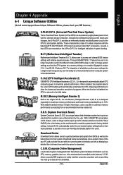
... their system. feature the user is returned to change BIOS feature settings with the option for solid system stability. C.I.A.2 (CPU Intelligent Accelerator 2) GIGABYTE CPU Intelligent Accelerator 2(C.I .B. 2 features. feature, users no longer required to switch into a single mode now gives any user...user PC and provides the user with the latest LGA775 Intel® Pentium® 4 Processor as well as the CPU system bus, memory timings or to enabled Gigabyte's unique C.I.A. 2 and M.I .A. 2) is a revolutionary eight-phase power circuit built for intelligent indication of programs....
... their system. feature the user is returned to change BIOS feature settings with the option for solid system stability. C.I.A.2 (CPU Intelligent Accelerator 2) GIGABYTE CPU Intelligent Accelerator 2(C.I .B. 2 features. feature, users no longer required to switch into a single mode now gives any user...user PC and provides the user with the latest LGA775 Intel® Pentium® 4 Processor as well as the CPU system bus, memory timings or to enabled Gigabyte's unique C.I.A. 2 and M.I .A. 2) is a revolutionary eight-phase power circuit built for intelligent indication of programs....


