Manual
Page 4
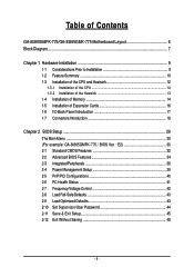
... CPU 12 1-3-2 Installation of the Heatsink 13 1-4 Installation of Memory 14 1-5 Installation of Expansion Cards 16 1-6 I/O Back Panel Introduction 17 1-7 Connectors Introduction 18 Chapter 2 BIOS Setup 29 The Main Menu ...30 (For example: GA-8I865GMFK-775 / BIOS Ver. : E2 30 2-1 Standard CMOS Features 32 2-2 Advanced BIOS Features 34 2-3 IntegratedPeripherals 36 2-4 Power Management Setup 39 2-5 PnP/PCI Configurations 40 2-6 PC Health Status 41 2-7 Frequency/Voltage Control 42 2-8 Load Fail-Safe Defaults 43 2-9 Load Optimized Defaults 43 2-10 Set Supervisor/User Password 44...
... CPU 12 1-3-2 Installation of the Heatsink 13 1-4 Installation of Memory 14 1-5 Installation of Expansion Cards 16 1-6 I/O Back Panel Introduction 17 1-7 Connectors Introduction 18 Chapter 2 BIOS Setup 29 The Main Menu ...30 (For example: GA-8I865GMFK-775 / BIOS Ver. : E2 30 2-1 Standard CMOS Features 32 2-2 Advanced BIOS Features 34 2-3 IntegratedPeripherals 36 2-4 Power Management Setup 39 2-5 PnP/PCI Configurations 40 2-6 PC Health Status 41 2-7 Frequency/Voltage Control 42 2-8 Load Fail-Safe Defaults 43 2-9 Load Optimized Defaults 43 2-10 Set Supervisor/User Password 44...
Manual
Page 10
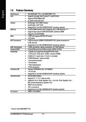
... Summary Motherboard CPU Chipset Memory Slots IDE Connections FDD Connections Onboard SATA Peripherals Onboard LAN Onboard Audio I/O Control Š GA-8I865GMK-775 or GA-8I865GMFK-775 Š Supports the latest Intel® Pentium® 4 LGA775 CPU Š Supports 800/533MHz FSB Š L2 cache varies with CPU Š Northbridge: Intel® 865G Chipset Š Southbridge: Intel® ICH5 Š Supported on the Win 98/ME/2000/XP operating systems Š 4 DDR DIMM memory slots (supports up to 4GB memory) (Note) Š Supports dual channel...
... Summary Motherboard CPU Chipset Memory Slots IDE Connections FDD Connections Onboard SATA Peripherals Onboard LAN Onboard Audio I/O Control Š GA-8I865GMK-775 or GA-8I865GMFK-775 Š Supports the latest Intel® Pentium® 4 LGA775 CPU Š Supports 800/533MHz FSB Š L2 cache varies with CPU Š Northbridge: Intel® 865G Chipset Š Southbridge: Intel® ICH5 Š Supported on the Win 98/ME/2000/XP operating systems Š 4 DDR DIMM memory slots (supports up to 4GB memory) (Note) Š Supports dual channel...
Manual
Page 20
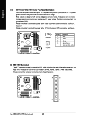
... 33 2 1 GA-8I865GM(F)K-775 Motherboard - 20 - The types of the cable connects to prevent CPU overheating and failure. 1 CPU_FAN 1 SYS_FAN Pin No. 1 2 3 4 Definition GND +12V Sense Speed Control (Only for CPU_FAN) power connector and possesses a foolproof connection design. English 3/4) CPU_FAN / SYS_FAN (Cooler Fan Power Connector) The cooler fan power connector supplies a +12V power voltage via a 3-pin/4-pin(only for CPU_FAN) 5) FDD (FDD Connector) The FDD connector is the ground wire (GND). Please remember to connect the power to the CPU fan to...
... 33 2 1 GA-8I865GM(F)K-775 Motherboard - 20 - The types of the cable connects to prevent CPU overheating and failure. 1 CPU_FAN 1 SYS_FAN Pin No. 1 2 3 4 Definition GND +12V Sense Speed Control (Only for CPU_FAN) power connector and possesses a foolproof connection design. English 3/4) CPU_FAN / SYS_FAN (Cooler Fan Power Connector) The cooler fan power connector supplies a +12V power voltage via a 3-pin/4-pin(only for CPU_FAN) 5) FDD (FDD Connector) The FDD connector is the ground wire (GND). Please remember to connect the power to the CPU fan to...
Manual
Page 21
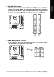
... IDE cable can provide up to two IDE devices (hard drive or optical drive). Definition 7 1 1 GND 2 TXP 3 TXN 4 GND 5 RXN 6 RXP 7 GND - 21 - One IDE connector can connect to one IDE device as Master and the other as Slave (for the Serial ATA and install the proper driver in order to the computer via an IDE connector. Pin No. If you wish to connect two IDE devices, please set the jumper on the IDE device...
... IDE cable can provide up to two IDE devices (hard drive or optical drive). Definition 7 1 1 GND 2 TXP 3 TXN 4 GND 5 RXN 6 RXP 7 GND - 21 - One IDE connector can connect to one IDE device as Master and the other as Slave (for the Serial ATA and install the proper driver in order to the computer via an IDE connector. Pin No. If you wish to connect two IDE devices, please set the jumper on the IDE device...
Manual
Page 22
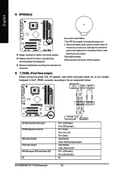
... Disk Active LED) SPEAK (Speaker Connector) RES (Reset Switch) PW (Power Switch) MSG(Message LED/Power/Sleep LED) NC GA-8I865GM(F)K-775 Motherboard IDE Hard Disk Active LED Reset Switch Pin 1: LED anode(+) Pin 2: LED cathode(-) Pin 1: Power Pin 2- Pin 3: NC Pin 4: Data(-) Open: Normal Close: Reset Hardware System Open: Normal Close: Power On/Off Pin 1: LED anode(+) Pin 2: LED cathode(-) NC - 22 - Dispose of explosion if battery is incorrectly replaced. Take out the battery gently and put it aside for one minute). 3.Re-install the battery. 4.Plug the power cord and turn...
... Disk Active LED) SPEAK (Speaker Connector) RES (Reset Switch) PW (Power Switch) MSG(Message LED/Power/Sleep LED) NC GA-8I865GM(F)K-775 Motherboard IDE Hard Disk Active LED Reset Switch Pin 1: LED anode(+) Pin 2: LED cathode(-) Pin 1: Power Pin 2- Pin 3: NC Pin 4: Data(-) Open: Normal Close: Reset Hardware System Open: Normal Close: Power On/Off Pin 1: LED anode(+) Pin 2: LED cathode(-) NC - 22 - Dispose of explosion if battery is incorrectly replaced. Take out the battery gently and put it aside for one minute). 3.Re-install the battery. 4.Plug the power cord and turn...
Manual
Page 30
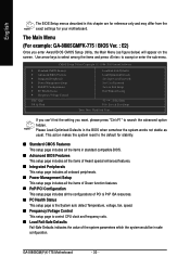
... System auto detect Temperature, voltage, fan, speed. „ Frequency/Voltage Control This setup page is control CPU clock and frequency ratio. „ Load Fail-Safe Defaults Fail-Safe Defaults indicates the value of the system parameters which the system would be in the BIOS when somehow the system works not stable as figure below) will appear on the screen. GA-8I865GM(F)K-775 Motherboard - 30 - If you can't find the setting you enter Award BIOS CMOS Setup Utility, the Main Menu (as usual. Use arrow keys...
... System auto detect Temperature, voltage, fan, speed. „ Frequency/Voltage Control This setup page is control CPU clock and frequency ratio. „ Load Fail-Safe Defaults Fail-Safe Defaults indicates the value of the system parameters which the system would be in the BIOS when somehow the system works not stable as figure below) will appear on the screen. GA-8I865GM(F)K-775 Motherboard - 30 - If you can't find the setting you enter Award BIOS CMOS Setup Utility, the Main Menu (as usual. Use arrow keys...
Manual
Page 32
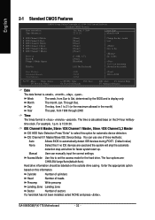
... times format in . User can use one of sectors If a hard disk has not been installed, select NONE and press . The four options are used and the system will skip the automatic Manual detection step and allow for automatic device detection. is , , , . GA-8I865GM(F)K-775 Motherboard - 32 - Enter the appropriate option based on the 24-hour militarytime clock. The time is display only Month The month...
... times format in . User can use one of sectors If a hard disk has not been installed, select NONE and press . The four options are used and the system will skip the automatic Manual detection step and allow for automatic device detection. is , , , . GA-8I865GM(F)K-775 Motherboard - 32 - Enter the appropriate option based on the 24-hour militarytime clock. The time is display only Month The month...
Manual
Page 36
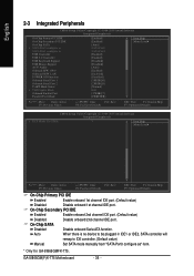
...Chip Secondary PCI IDE Enabled Enable onboard 2nd channel IDE port. (Default value) Disabled Disable onboard 2nd channel IDE port. GA-8I865GM(F)K-775 Motherboard - 36 - Auto When there is no device to be plugged in IDE1 or IDE2, SATA controller will remap to IDE controller. (Default value) Manual Set SATA mode manually from "SATA Port0 configure as USB Controller USB 2.0 Controller USB Keyboard Support USB Mouse Support AC97 Audio Onboard H/W 1394* Onboard H/W LAN POWER ON Function Onboard Serial Port 1 Onboard Serial Port 2 UART Mode Select x UR2 Duplex Mode Onboard Parallel Port...
...Chip Secondary PCI IDE Enabled Enable onboard 2nd channel IDE port. (Default value) Disabled Disable onboard 2nd channel IDE port. GA-8I865GM(F)K-775 Motherboard - 36 - Auto When there is no device to be plugged in IDE1 or IDE2, SATA controller will remap to IDE controller. (Default value) Manual Set SATA mode manually from "SATA Port0 configure as USB Controller USB 2.0 Controller USB Keyboard Support USB Mouse Support AC97 Audio Onboard H/W 1394* Onboard H/W LAN POWER ON Function Onboard Serial Port 1 Onboard Serial Port 2 UART Mode Select x UR2 Duplex Mode Onboard Parallel Port...
Manual
Page 37
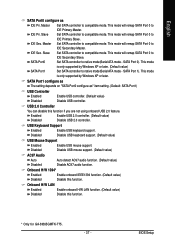
... GA-8I865GMFK-775. - 37 - This mode will remap SATA Port 0 to native mode(Serial ATA mode - English SATA Port0 configure as " item setting. (Default: SATA Port1) USB Controller Enabled Disabled Enable USB controller. (Default value) Disable USB controller. Master IDE Pri. Slave Set SATA controller to IDE Secondary Slave. This mode will remap SATA Port 0 to compatible mode. Master IDE Primary Slave. This mode is only supported by Windows XP or later. USB 2.0 Controller You can disable this function if you are not using onboard USB 2.0 feature. USB Keyboard Support...
... GA-8I865GMFK-775. - 37 - This mode will remap SATA Port 0 to native mode(Serial ATA mode - English SATA Port0 configure as " item setting. (Default: SATA Port1) USB Controller Enabled Disabled Enable USB controller. (Default value) Disable USB controller. Master IDE Pri. Slave Set SATA controller to IDE Secondary Slave. This mode will remap SATA Port 0 to compatible mode. Master IDE Primary Slave. This mode is only supported by Windows XP or later. USB 2.0 Controller You can disable this function if you are not using onboard USB 2.0 feature. USB Keyboard Support...

Manual
Page 41
...Current CPU/SYSTEM FAN Speed (RPM) Detect CPU/SYSTEM Fan speed status automatically. Users can be used for it. (Default Value) Set to PWM when you use a CPU fan with 3-pin or 4-pin power cables. Current Voltage(V) Vcore / +3.3V / +5V / +12V / DDR25V Detect system's voltage status automatically. Auto Voltage BIOS autodetects the type of CPU fan you installed and sets the optimal CPU Smart FAN control mode for CPU fans with a 4-pin fan power cable. English 2-6 PC Health Status CMOS Setup Utility-Copyright (C) 1984-2005 Award Software PC Health Status Current CPU Temperature...
...Current CPU/SYSTEM FAN Speed (RPM) Detect CPU/SYSTEM Fan speed status automatically. Users can be used for it. (Default Value) Set to PWM when you use a CPU fan with 3-pin or 4-pin power cables. Current Voltage(V) Vcore / +3.3V / +5V / +12V / DDR25V Detect system's voltage status automatically. Auto Voltage BIOS autodetects the type of CPU fan you installed and sets the optimal CPU Smart FAN control mode for CPU fans with a 4-pin fan power cable. English 2-6 PC Health Status CMOS Setup Utility-Copyright (C) 1984-2005 Award Software PC Health Status Current CPU Temperature...
Manual
Page 44
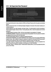
... Password CMOS Setup Utility-Copyright (C) 1984-2005 Award Software ` Standard CMOS Features ` Advanced BIOS Features ` Integrated Peripherals ` Power Management Setup ` PnP/PCI ConfigurationEsnter Password: ` PC Health Status ` Frequency/Voltage Control ESC: Quit F8: Q-Flash Load Fail-Safe Defaults Load Optimized Defaults Set Supervisor Password Set User Password Save & Exit Setup Exit Without Saving KLJI: Select Item F10: Save & Exit Setup Change/Set/Disable Password Selecting this function, the following message will appear at the center of the screen to confirm the password. Type...
... Password CMOS Setup Utility-Copyright (C) 1984-2005 Award Software ` Standard CMOS Features ` Advanced BIOS Features ` Integrated Peripherals ` Power Management Setup ` PnP/PCI ConfigurationEsnter Password: ` PC Health Status ` Frequency/Voltage Control ESC: Quit F8: Q-Flash Load Fail-Safe Defaults Load Optimized Defaults Set Supervisor Password Set User Password Save & Exit Setup Exit Without Saving KLJI: Select Item F10: Save & Exit Setup Change/Set/Disable Password Selecting this function, the following message will appear at the center of the screen to confirm the password. Type...
Manual
Page 52
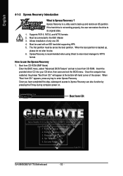
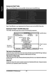
... Recovery is a utility used with an IDE hard disk supporting HPA 5. Insert the provided driver CD into your CD drive, then save and exit the BIOS menu. Set Password 5. How to NTFS format. Allows installation of the screen. Boot from CD-ROM (BMP Mode) Enter the BIOS menu, select "Advanced BIOS Feature" and set as the boot partition. Verifying DMI Pool Data Boot from CD: Boot from CD-ROM. Execute Restore Utility 3. Exit and Restart Build 2011 GA-8I865GM(F)K-775 Motherboard...
... Recovery is a utility used with an IDE hard disk supporting HPA 5. Insert the provided driver CD into your CD drive, then save and exit the BIOS menu. Set Password 5. How to NTFS format. Allows installation of the screen. Boot from CD-ROM (BMP Mode) Enter the BIOS menu, select "Advanced BIOS Feature" and set as the boot partition. Verifying DMI Pool Data Boot from CD: Boot from CD-ROM. Execute Restore Utility 3. Exit and Restart Build 2011 GA-8I865GM(F)K-775 Motherboard...
Manual
Page 56
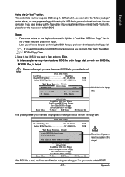
... Language Load Fail-Safe Defaults Load Optimized Defaults Set Supervisor Password Set User Password Save & Exit Setup Exit Without Saving F3: Change Language F10: Save & Exit Setup Time, Date, Hard Disk Type... Blocking a task and pressing Enter key on your keyboard to perform these actions. Blocking a task and pressing Enter key on your keyboard to operate the Q-Flash/Dual BIOS utility. GA-8I865GM(F)K-775 Motherboard - 56 - Task menu for Dual BIOS utility: Contains the names of four tasks. Exploring the Q-FlashTM / Dual BIOS utility screen The Q-Flash / Dual BIOS utility screen...
... Language Load Fail-Safe Defaults Load Optimized Defaults Set Supervisor Password Set User Password Save & Exit Setup Exit Without Saving F3: Change Language F10: Save & Exit Setup Time, Date, Hard Disk Type... Blocking a task and pressing Enter key on your keyboard to perform these actions. Blocking a task and pressing Enter key on your keyboard to operate the Q-Flash/Dual BIOS utility. GA-8I865GM(F)K-775 Motherboard - 56 - Task menu for Dual BIOS utility: Contains the names of four tasks. Exploring the Q-FlashTM / Dual BIOS utility screen The Q-Flash / Dual BIOS utility screen...
Manual
Page 57
... Error Disable Total sizeC: o1p.3y9MMain ROM DataFtroeeBsaiczkeu:p911.50K F5 : Refresh Load Default SeDttEinLg:sDelete Save Settings to CMOS Q-Flash Utility Load Main BIOS from Floppy Load Backup BIOS from Floppy" item in the Q-Flash menu and press Enter button. After pressing Enter, you'll then see a box pop up showing the BIOS files you how to your motherboard. Appendix English Using the Q-FlashTM utility: This section tells you previously downloaded to the floppy disk. In this stage!! Dual BIOS Utility Boot...
... Error Disable Total sizeC: o1p.3y9MMain ROM DataFtroeeBsaiczkeu:p911.50K F5 : Refresh Load Default SeDttEinLg:sDelete Save Settings to CMOS Q-Flash Utility Load Main BIOS from Floppy Load Backup BIOS from Floppy" item in the Q-Flash menu and press Enter button. After pressing Enter, you'll then see a box pop up showing the BIOS files you how to your motherboard. Appendix English Using the Q-FlashTM utility: This section tells you previously downloaded to the floppy disk. In this stage!! Dual BIOS Utility Boot...
Manual
Page 58
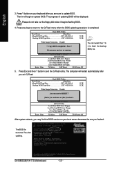
...DEL to update BIOS. Press Y button on your keyboard after updating. uCtopRyecBoIvOeSrycomEnpalebtled - English 3. Please do not take out the floppy disk when it will be displayed. Load Default Settings Save Settings to CMOS Q-Flash Utility Load Main BIOS from Floppy Load Backup BIOS from Floppy Save Main BIOS to Floppy Save Backup BIOS to Floppy Enter : Run :Move ESC:Reset F10:Power Off You can repeat Step 1 to 4 to the Q-Flash menu when the BIOS updating procedure is completed. Dual BIOS Utility Boot From Main Bios Main ROM Type/Size SST 49LF003A Backup ROM Type/Size SST...
...DEL to update BIOS. Press Y button on your keyboard after updating. uCtopRyecBoIvOeSrycomEnpalebtled - English 3. Please do not take out the floppy disk when it will be displayed. Load Default Settings Save Settings to CMOS Q-Flash Utility Load Main BIOS from Floppy Load Backup BIOS from Floppy Save Main BIOS to Floppy Save Backup BIOS to Floppy Enter : Run :Move ESC:Reset F10:Power Off You can repeat Step 1 to 4 to the Q-Flash menu when the BIOS updating procedure is completed. Dual BIOS Utility Boot From Main Bios Main ROM Type/Size SST 49LF003A Backup ROM Type/Size SST...
Manual
Page 59
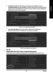
... the system redetects all devices after BIOS has been upgraded. Part Two: Updating BIOS with Q-FlashTM Utility on your keyboard to update BIOS using the Q-FlashTM utility. This part guides users of single-BIOS motherboards how to load defaults. 7. CMOS Setup Utility-Copyright (C) 1984-2004 Award Software Standard CMOS Features Select Language Advanced BIOS Features Load Fail-Safe Defaults Integrated Peripherals Load Optimized Defaults Power Management Setup Load Fail-Safe Defaults (YS/eNt )S?uYpervisor Password PnP/PCI Configurations Set User Password PC Health Status Save...
... the system redetects all devices after BIOS has been upgraded. Part Two: Updating BIOS with Q-FlashTM Utility on your keyboard to update BIOS using the Q-FlashTM utility. This part guides users of single-BIOS motherboards how to load defaults. 7. CMOS Setup Utility-Copyright (C) 1984-2004 Award Software Standard CMOS Features Select Language Advanced BIOS Features Load Fail-Safe Defaults Integrated Peripherals Load Optimized Defaults Power Management Setup Load Fail-Safe Defaults (YS/eNt )S?uYpervisor Password PnP/PCI Configurations Set User Password PC Health Status Save...
Manual
Page 62
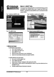
... file, downloading from internet or any other methods (such as: 865GMFK775.E2). Complete update process following the instruction. Fig 1. Installing the @BIOS utility Fig 2. The @BIOS utility Click " " Click "Update New BIOS" Fig 4. Update BIOS NOT through Internet a. Just select the desired @BIOS server to update their BIOS under Windows. Update BIOS through Internet: a. Select @BIOSTM sever d. e. GA-8I865GM(F)K-775 Motherboard - 62 - Click Sart/ Programs/ GIGABYTE/@BIOS Fig 3. Methods and steps: I. Select the exact model...
... file, downloading from internet or any other methods (such as: 865GMFK775.E2). Complete update process following the instruction. Fig 1. Installing the @BIOS utility Fig 2. The @BIOS utility Click " " Click "Update New BIOS" Fig 4. Update BIOS NOT through Internet a. Just select the desired @BIOS server to update their BIOS under Windows. Update BIOS through Internet: a. Select @BIOSTM sever d. e. GA-8I865GM(F)K-775 Motherboard - 62 - Click Sart/ Programs/ GIGABYTE/@BIOS Fig 3. Methods and steps: I. Select the exact model...
Manual
Page 65
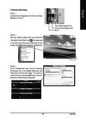
... 4-channel audio configuration. - 65 - Appendix STEP 2 : After you install the audio driver, you will find the "SoundMAX Control Panel" icon in the status area on the SoundMAX menu. You will find a multi-driver icon on the lower right of the screen. In the "Speaker Setup" box, click "Multi-drive" and then click "Apply". Right-click the icon to "Line In". English 4 Channel Audio Setup STEP 1 : Connect the Front Speakers...
... 4-channel audio configuration. - 65 - Appendix STEP 2 : After you install the audio driver, you will find the "SoundMAX Control Panel" icon in the status area on the SoundMAX menu. You will find a multi-driver icon on the lower right of the screen. In the "Speaker Setup" box, click "Multi-drive" and then click "Apply". Right-click the icon to "Line In". English 4 Channel Audio Setup STEP 1 : Connect the Front Speakers...
Manual
Page 66
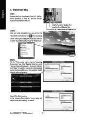
... Configuration: At the "Acoustic Environments" menu, users can adjust sound option settings as desired. GA-8I865GM(F)K-775 Motherboard - 66 - You will find a surround sound speakers icon on the lower right of the screen. This completes the 5.1 channel audio configuration. English 5.1 Channel Audio Setup STEP 1 : Connect the Front Speakers to "Line Out", the Surround Speakers to "Line In", and the Center/ Subwoofer Speakers to select "SoundMAX Control Panel" or "Preferences". In the "Speaker Setup" box, click "Surround Sound Speakers...
... Configuration: At the "Acoustic Environments" menu, users can adjust sound option settings as desired. GA-8I865GM(F)K-775 Motherboard - 66 - You will find a surround sound speakers icon on the lower right of the screen. This completes the 5.1 channel audio configuration. English 5.1 Channel Audio Setup STEP 1 : Connect the Front Speakers to "Line Out", the Surround Speakers to "Line In", and the Center/ Subwoofer Speakers to select "SoundMAX Control Panel" or "Preferences". In the "Speaker Setup" box, click "Surround Sound Speakers...
Manual
Page 68
... and F1 keys after turning up . gate A20 failure 7 beeps Processor exception interrupt error 8 beeps Display memory read/write failure 1 short: System boots successfully 2 short: CMOS setting error 1 long 1 short: DRAM or M/B error 1 long 2 short: Monitor or display card error 1 long 3 short: Keyboard error 9 beeps ROM checksum error 1 long 9 short: BIOS ROM error 10 beeps CMOS shutdown register read/write error Continuous long beeps: DRAM error 11 beeps Cache memory bad Continuous short beeps: Power error GA-8I865GM(F)K-775 Motherboard - 68 - English 4-2 Troubleshooting Below...
... and F1 keys after turning up . gate A20 failure 7 beeps Processor exception interrupt error 8 beeps Display memory read/write failure 1 short: System boots successfully 2 short: CMOS setting error 1 long 1 short: DRAM or M/B error 1 long 2 short: Monitor or display card error 1 long 3 short: Keyboard error 9 beeps ROM checksum error 1 long 9 short: BIOS ROM error 10 beeps CMOS shutdown register read/write error Continuous long beeps: DRAM error 11 beeps Cache memory bad Continuous short beeps: Power error GA-8I865GM(F)K-775 Motherboard - 68 - English 4-2 Troubleshooting Below...


