Manual
Page 1
GA-890XA-UD3 AM3 socket motherboard for AMD Phenom™ II processor/AMD Athlon™ II processor User's Manual Rev. 1001 12ME-890XAD3-1001R
GA-890XA-UD3 AM3 socket motherboard for AMD Phenom™ II processor/AMD Athlon™ II processor User's Manual Rev. 1001 12ME-890XAD3-1001R
Manual
Page 2
Motherboard GA-890XA-UD3 Mar. 2, 2010 Motherboard GA-890XA-UD3 Mar. 2, 2010
Motherboard GA-890XA-UD3 Mar. 2, 2010 Motherboard GA-890XA-UD3 Mar. 2, 2010
Manual
Page 3
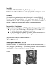
... and features in this manual may be made by GIGABYTE without GIGABYTE's prior written permission. No part of this product, GIGABYTE provides the following types of documentations: For quick set-up of the motherboard is the property of this manual may be reproduced... X.X." Documentation Classifications In order to their respective owners. For product-related information, check on our website at: http://www.gigabyte.com.tw Identifying Your Motherboard Revision The revision number on our website. Example: Copyright © 2010 GIGA-BYTE TECHNOLOGY CO., LTD. For example,...
... and features in this manual may be made by GIGABYTE without GIGABYTE's prior written permission. No part of this product, GIGABYTE provides the following types of documentations: For quick set-up of the motherboard is the property of this manual may be reproduced... X.X." Documentation Classifications In order to their respective owners. For product-related information, check on our website at: http://www.gigabyte.com.tw Identifying Your Motherboard Revision The revision number on our website. Example: Copyright © 2010 GIGA-BYTE TECHNOLOGY CO., LTD. For example,...
Manual
Page 4
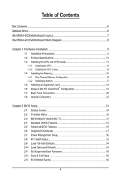
Table of Contents Box Contents...6 Optional Items...6 GA-890XA-UD3 Motherboard Layout 7 GA-890XA-UD3 Motherboard Block Diagram 8 Chapter 1 Hardware Installation 9 1-1 Installation Precautions 9 1-2 Product Specifications 10 1-3 Installing the CPU and CPU Cooler 13 1-3-1 Installing the CPU 13 1-3-2 Installing the CPU Cooler ...
Table of Contents Box Contents...6 Optional Items...6 GA-890XA-UD3 Motherboard Layout 7 GA-890XA-UD3 Motherboard Block Diagram 8 Chapter 1 Hardware Installation 9 1-1 Installation Precautions 9 1-2 Product Specifications 10 1-3 Installing the CPU and CPU Cooler 13 1-3-1 Installing the CPU 13 1-3-2 Installing the CPU Cooler ...

Manual
Page 6
...-1IE008-0*R) 2-port SATA power cable (Part No. 12CF1-2SERPW-0*R) S/PDIF In cable (Part No. 12CR1-1SPDIN-0*R) COM port cable (Part No. 12CF1-1CM001-3*R) - 6 - Box Contents GA-890XA-UD3 motherboard Motherboard driver disk User's Manual Quick Installation Guide One IDE cable Four SATA 3Gb/s cables I/O Shield • The box contents above are subject to change without...
...-1IE008-0*R) 2-port SATA power cable (Part No. 12CF1-2SERPW-0*R) S/PDIF In cable (Part No. 12CR1-1SPDIN-0*R) COM port cable (Part No. 12CF1-1CM001-3*R) - 6 - Box Contents GA-890XA-UD3 motherboard Motherboard driver disk User's Manual Quick Installation Guide One IDE cable Four SATA 3Gb/s cables I/O Shield • The box contents above are subject to change without...
Manual
Page 7
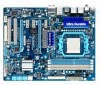
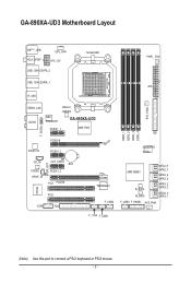
GA-890XA-UD3 Motherboard Layout KB(Note)_USB RCA_SPDIF CPU_FAN ATX_12V USB_1394_ESATA_2 Socket AM3 PWR__FAN USB_1394_ESATA_1 ATX R_USB USB30_LAN AUDIO NEC D720200F1 JMicron JMB362 GA-890XA-UD3 PCIEX1_1 AMD 790X F_AUDIO RTL8111D PCIEX16 PCIEX1_2 DDR3_1 DDR3_2 DDR3_3 DDR3_4 SYS_FAN2 IDE GIGABYTE SATA2 CD_IN CODEC SPDIF_IN SPDIF_OUT CLR_CMOS BAT PCIEX1_3 PCI1 PCIEX8 IT8720 PCI2 COM FDD TSB43AB23 F_USB2 AMD SB850...
GA-890XA-UD3 Motherboard Layout KB(Note)_USB RCA_SPDIF CPU_FAN ATX_12V USB_1394_ESATA_2 Socket AM3 PWR__FAN USB_1394_ESATA_1 ATX R_USB USB30_LAN AUDIO NEC D720200F1 JMicron JMB362 GA-890XA-UD3 PCIEX1_1 AMD 790X F_AUDIO RTL8111D PCIEX16 PCIEX1_2 DDR3_1 DDR3_2 DDR3_3 DDR3_4 SYS_FAN2 IDE GIGABYTE SATA2 CD_IN CODEC SPDIF_IN SPDIF_OUT CLR_CMOS BAT PCIEX1_3 PCI1 PCIEX8 IT8720 PCI2 COM FDD TSB43AB23 F_USB2 AMD SB850...
Manual
Page 8
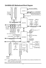
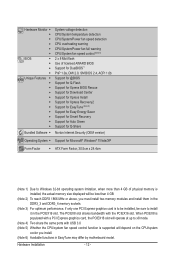
GA-890XA-UD3 Motherboard Block Diagram 1 PCIe x 16 2 PCIe x 8 CPU CLK+/- (200 MHz) PCIe CLK (100 MHz) or AM3 CPU DDR3 1866(O.C.)(Note 1)/1333/1066 MHz Dual Channel Memory ... PCI Express Bus PCIe CLK (100 MHz) x1 x1 x1 RTL8111D RJ45 3 PCI Express x1 LAN ATA-133/100/66/33 IDE Channel 2 SATA 3Gb/s GIGABYTE SATA2 PCI Express Bus PCI Bus TSB43AB23 AMD 790X AMD SB850 CODEC JMicron NEC JMB362 D720200F1 PCI Express Bus 16 USB 2.0/1.1(Note 2) 6 SATA 6Gb/s Dual...
GA-890XA-UD3 Motherboard Block Diagram 1 PCIe x 16 2 PCIe x 8 CPU CLK+/- (200 MHz) PCIe CLK (100 MHz) or AM3 CPU DDR3 1866(O.C.)(Note 1)/1333/1066 MHz Dual Channel Memory ... PCI Express Bus PCIe CLK (100 MHz) x1 x1 x1 RTL8111D RJ45 3 PCI Express x1 LAN ATA-133/100/66/33 IDE Channel 2 SATA 3Gb/s GIGABYTE SATA2 PCI Express Bus PCI Bus TSB43AB23 AMD 790X AMD SB850 CODEC JMicron NEC JMB362 D720200F1 PCI Express Bus 16 USB 2.0/1.1(Note 2) 6 SATA 6Gb/s Dual...
Manual
Page 9
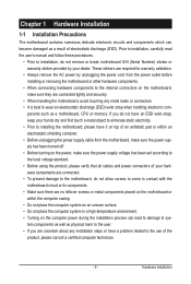
...supply has been turned off. • Before turning on the power, make sure they are connected tightly and securely. • When handling the motherboard, avoid touching any installation steps or have it on top of an antistatic pad or within the computer casing. • Do not place the...• When connecting hardware components to the internal connectors on an uneven surface. • Do not place the computer system in contact with the motherboard circuit or its components. • Make sure there are uncertain about any metal leads or connectors. • It is best to wear an ...
...supply has been turned off. • Before turning on the power, make sure they are connected tightly and securely. • When handling the motherboard, avoid touching any installation steps or have it on top of an antistatic pad or within the computer casing. • Do not place the...• When connecting hardware components to the internal connectors on an uneven surface. • Do not place the computer system in contact with the motherboard circuit or its components. • Make sure there are uncertain about any metal leads or connectors. • It is best to wear an ...
Manual
Page 12
... slot. When PCIEX8 is populated with a PCI Express graphics card, the PCIEX16 slot will operate at up to install it in EasyTune may differ by motherboard model.
... slot. When PCIEX8 is populated with a PCI Express graphics card, the PCIEX16 slot will operate at up to install it in EasyTune may differ by motherboard model.
Manual
Page 13
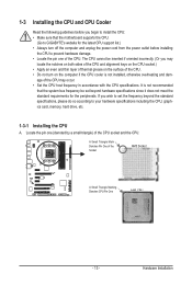
... the computer and unplug the power cord from the power outlet before you begin to install the CPU: • Make sure that the motherboard supports the CPU. (Go to GIGABYTE's website for the peripherals. 1-3 Installing the CPU and CPU Cooler Read the following guidelines before installing the CPU to prevent hardware damage...
... the computer and unplug the power cord from the power outlet before you begin to install the CPU: • Make sure that the motherboard supports the CPU. (Go to GIGABYTE's website for the peripherals. 1-3 Installing the CPU and CPU Cooler Read the following guidelines before installing the CPU to prevent hardware damage...
Manual
Page 14
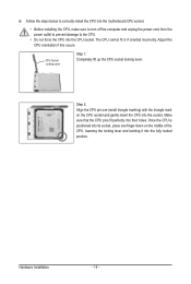
... CPU cannot fit in if oriented incorrectly. Adjust the CPU orientation if this occurs. Follow the steps below to correctly install the CPU into the motherboard CPU socket. • Before installing the CPU, make sure to turn off the computer and unplug the power cord from the power outlet to prevent...
... CPU cannot fit in if oriented incorrectly. Adjust the CPU orientation if this occurs. Follow the steps below to correctly install the CPU into the motherboard CPU socket. • Before installing the CPU, make sure to turn off the computer and unplug the power cord from the power outlet to prevent...
Manual
Page 15
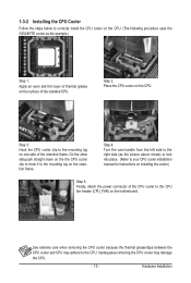
...5: Finally, attach the power connector of the CPU cooler to correctly install the CPU cooler on the CPU. (The following procedure uses the GIGABYTE cooler as the example.) Step 1: Apply an even and thin layer of thermal grease on the surface of the retention frame. Hardware Installation ...1-3-2 Installing the CPU Cooler Follow the steps below to the CPU fan header (CPU_FAN) on the motherboard. Inadequately removing the CPU cooler may adhere to the mounting lug on the retention frame. Step 3: Hook the CPU cooler clip to the...
...5: Finally, attach the power connector of the CPU cooler to correctly install the CPU cooler on the CPU. (The following procedure uses the GIGABYTE cooler as the example.) Step 1: Apply an even and thin layer of thermal grease on the surface of the retention frame. Hardware Installation ...1-3-2 Installing the CPU Cooler Follow the steps below to the CPU fan header (CPU_FAN) on the motherboard. Inadequately removing the CPU cooler may adhere to the mounting lug on the retention frame. Step 3: Hook the CPU cooler clip to the...
Manual
Page 16
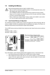
...memory to install the memory: • Make sure that memory of the same capacity, brand, speed, and chips be used . (Go to GIGABYTE's website for optimum performance. Hardware Installation - 16 - DS/SS DS/SS Four Modules DS/SS DS/SS DS/SS DS/SS (SS=Single... DS=Double-Sided, "- -"=No Memory) DDR3_1 DDR3_2 DDR3_3 DDR3_4 Due to insert the memory, switch the direction. 1-4-1 Dual Channel Memory Configuration This motherboard provides four DDR3 memory sockets and supports Dual Channel Technology. If you begin to prevent hardware damage. • Memory modules have a foolproof design....
...memory to install the memory: • Make sure that memory of the same capacity, brand, speed, and chips be used . (Go to GIGABYTE's website for optimum performance. Hardware Installation - 16 - DS/SS DS/SS Four Modules DS/SS DS/SS DS/SS DS/SS (SS=Single... DS=Double-Sided, "- -"=No Memory) DDR3_1 DDR3_2 DDR3_3 DDR3_4 Due to insert the memory, switch the direction. 1-4-1 Dual Channel Memory Configuration This motherboard provides four DDR3 memory sockets and supports Dual Channel Technology. If you begin to prevent hardware damage. • Memory modules have a foolproof design....
Manual
Page 17
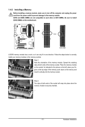
..., make sure to turn off the computer and unplug the power cord from the power outlet to prevent damage to install DDR3 DIMMs on this motherboard.
..., make sure to turn off the computer and unplug the power cord from the power outlet to prevent damage to install DDR3 DIMMs on this motherboard.
Manual
Page 18
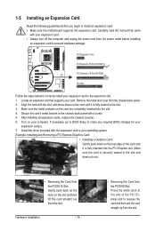
... the slot and then lift the card straight out from the power outlet before you begin to install an expansion card: • Make sure the motherboard supports the expansion card. Example: Installing and Removing a PCI Express Graphics Card: • Installing a Graphics Card: Gently push down on the card are completely inserted...
... the slot and then lift the card straight out from the power outlet before you begin to install an expansion card: • Make sure the motherboard supports the expansion card. Example: Installing and Removing a PCI Express Graphics Card: • Installing a Graphics Card: Gently push down on the card are completely inserted...
Manual
Page 19
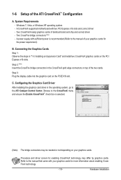
...) Insert the CrossFire bridge connectors in the operating system, go to the manual that came with your graphics cards for the power requirement) B. A CrossFireX-supported motherboard with sufficient power is selected. (Note) The bridge connectors may differ by graphics cards. Step 3: Plug the display cable into the graphics card on the...
...) Insert the CrossFire bridge connectors in the operating system, go to the manual that came with your graphics cards for the power requirement) B. A CrossFireX-supported motherboard with sufficient power is selected. (Note) The bridge connectors may differ by graphics cards. Step 3: Plug the display cable into the graphics card on the...
Manual
Page 20
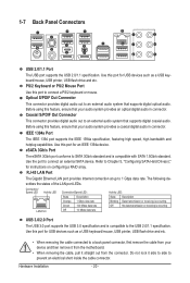
... and etc. • When removing the cable connected to a back panel connector, first remove the cable from your device and then remove it from the motherboard. • When removing the cable, pull it side to side to an external audio system that your audio system provides a coaxial digital audio in connector...
... and etc. • When removing the cable connected to a back panel connector, first remove the cable from your device and then remove it from the motherboard. • When removing the cable, pull it side to side to an external audio system that your audio system provides a coaxial digital audio in connector...

Manual
Page 22
...) F_AUDIO 13) CD_IN 14) SPDIF_IN 15) SPDIF_OUT 16) F_USB1/F_USB2/F_USB3 17) F_1394 18) COM 19) CLR_CMOS Read the following guidelines before turning on the motherboard.
...) F_AUDIO 13) CD_IN 14) SPDIF_IN 15) SPDIF_OUT 16) F_USB1/F_USB2/F_USB3 17) F_1394 18) COM 19) CLR_CMOS Read the following guidelines before turning on the motherboard.
Manual
Page 23
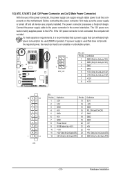
... for 2x12-pin ATX) GND (Only for 2x12-pin ATX) - 23 - To meet expansion requirements, it is turned off and all the components on the motherboard.
... for 2x12-pin ATX) GND (Only for 2x12-pin ATX) - 23 - To meet expansion requirements, it is turned off and all the components on the motherboard.
Manual
Page 24
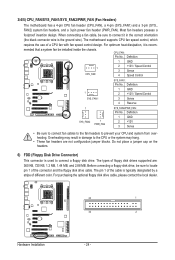
... to the fan headers to connect it is the ground wire). The pin 1 of different color. 3/4/5) CPU_FAN/SYS_FAN1/SYS_FAN2/PWR_FAN (Fan Headers) The motherboard has a 4-pin CPU fan header (CPU_FAN), a 4-pin (SYS_FAN1) and a 3-pin (SYS_ FAN2) system fan headers, and a 3-pin power...Control 3 Sense 4 Reserve 1 SYS_FAN2 1 PWR_FAN SYS_FAN2/PWR_FAN: Pin No. The types of a CPU fan with fan speed control design. The motherboard supports CPU fan speed control, which requires the use of floppy disk drives supported are not configuration jumper blocks. When connecting a fan cable, be...
... to the fan headers to connect it is the ground wire). The pin 1 of different color. 3/4/5) CPU_FAN/SYS_FAN1/SYS_FAN2/PWR_FAN (Fan Headers) The motherboard has a 4-pin CPU fan header (CPU_FAN), a 4-pin (SYS_FAN1) and a 3-pin (SYS_ FAN2) system fan headers, and a 3-pin power...Control 3 Sense 4 Reserve 1 SYS_FAN2 1 PWR_FAN SYS_FAN2/PWR_FAN: Pin No. The types of a CPU fan with fan speed control design. The motherboard supports CPU fan speed control, which requires the use of floppy disk drives supported are not configuration jumper blocks. When connecting a fan cable, be...


