Manual
Page 3
... legally registered to assist in any form or by GIGABYTE without GIGABYTE's prior written permission. The trademarks mentioned in this manual may be reproduced, copied, translated, transmitted, or published in the use GIGABYTE's unique features, read or download the information on/from the Support&Downloads\Motherboard\Technology Guide page on your motherboard revision before updating motherboard BIOS, drivers, or when looking for technical information. All rights...
... legally registered to assist in any form or by GIGABYTE without GIGABYTE's prior written permission. The trademarks mentioned in this manual may be reproduced, copied, translated, transmitted, or published in the use GIGABYTE's unique features, read or download the information on/from the Support&Downloads\Motherboard\Technology Guide page on your motherboard revision before updating motherboard BIOS, drivers, or when looking for technical information. All rights...
Manual
Page 4
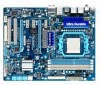
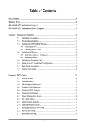
...890XA-UD3 Motherboard Layout 7 GA-890XA-UD3 Motherboard Block Diagram 8 Chapter 1 Hardware Installation 9 1-1 Installation Precautions 9 1-2 Product Specifications 10 1-3 Installing the CPU and CPU Cooler 13 1-3-1 Installing the CPU 13 1-3-2 Installing the CPU Cooler 15 1-4 Installing the Memory 16 1-4-1 Dual Channel Memory Configuration 16 1-4-2 Installing a Memory 17 1-5 Installing an Expansion Card 18 1-6 Setup of the ATI CrossFireX™ Configuration 19 1-7 Back Panel Connectors 20 1-8 Internal Connectors 22 Chapter 2 BIOS Setup 33 2-1 Startup Screen 34 2-2 The Main Menu...
...890XA-UD3 Motherboard Layout 7 GA-890XA-UD3 Motherboard Block Diagram 8 Chapter 1 Hardware Installation 9 1-1 Installation Precautions 9 1-2 Product Specifications 10 1-3 Installing the CPU and CPU Cooler 13 1-3-1 Installing the CPU 13 1-3-2 Installing the CPU Cooler 15 1-4 Installing the Memory 16 1-4-1 Dual Channel Memory Configuration 16 1-4-2 Installing a Memory 17 1-5 Installing an Expansion Card 18 1-6 Setup of the ATI CrossFireX™ Configuration 19 1-7 Back Panel Connectors 20 1-8 Internal Connectors 22 Chapter 2 BIOS Setup 33 2-1 Startup Screen 34 2-2 The Main Menu...
Manual
Page 10
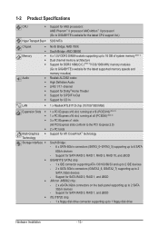
...- 2 x SATA 3Gb/s connectors (GSATA2_6, GSATA2_7) supporting up to 2 SATA 3Gb/s devices - Support for SATA RAID 0, RAID 1, and JBOD iTE IT8720 chip: - 1 x floppy disk drive connector supporting up to 6 SATA 6Gb/s devices - 1-2 Product Specifications CPU Support for AM3 processors: AMD Phenom™ II processor/ AMD Athlon™ II processor/ (Go to GIGABYTE's website for the latest CPU support list.) Hyper Transport Bus 5200 MT/s Chipset Memory Audio ...
...- 2 x SATA 3Gb/s connectors (GSATA2_6, GSATA2_7) supporting up to 2 SATA 3Gb/s devices - Support for SATA RAID 0, RAID 1, and JBOD iTE IT8720 chip: - 1 x floppy disk drive connector supporting up to 6 SATA 6Gb/s devices - 1-2 Product Specifications CPU Support for AM3 processors: AMD Phenom™ II processor/ AMD Athlon™ II processor/ (Go to GIGABYTE's website for the latest CPU support list.) Hyper Transport Bus 5200 MT/s Chipset Memory Audio ...
Manual
Page 19
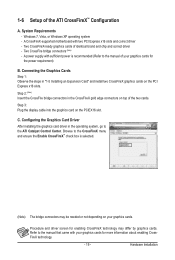
...; Configuration A. A CrossFireX-supported motherboard with your graphics cards. A power supply with sufficient power is selected. (Note) The bridge connectors may be needed or not depending on top of identical brand and chip and correct driver - Step 3: Plug the display cable into the graphics card on the PCI Express x16 slots. Configuring the Graphics Card Driver After installing the graphics card driver in the operating system, go to the manual that came with two PCI Express x16 slots and correct driver - C. Windows 7, Vista, or Windows...
...; Configuration A. A CrossFireX-supported motherboard with your graphics cards. A power supply with sufficient power is selected. (Note) The bridge connectors may be needed or not depending on top of identical brand and chip and correct driver - Step 3: Plug the display cable into the graphics card on the PCI Express x16 slots. Configuring the Graphics Card Driver After installing the graphics card driver in the operating system, go to the manual that came with two PCI Express x16 slots and correct driver - C. Windows 7, Vista, or Windows...
Manual
Page 31
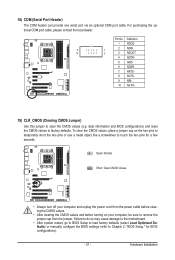
... optional COM port cable, please contact the local dealer. Failure to do so may cause damage to the motherboard. • After system restart, go to BIOS Setup to load factory defaults (select Load Optimized Defaults) or manually configure the BIOS settings (refer to clear the CMOS values (e.g. Hardware Installation Pin No. Definition 1 NDCD- 9 1 2 NSIN 10 2 3 NSOUT 4 NDTR- 5 GND 6 NDSR- 7 NRTS- 8 NCTS- 9 NRI- 10 No Pin 19) CLR_CMOS (Clearing CMOS Jumper) Use this jumper to Chapter 2, "BIOS Setup...
... optional COM port cable, please contact the local dealer. Failure to do so may cause damage to the motherboard. • After system restart, go to BIOS Setup to load factory defaults (select Load Optimized Defaults) or manually configure the BIOS settings (refer to clear the CMOS values (e.g. Hardware Installation Pin No. Definition 1 NDCD- 9 1 2 NSIN 10 2 3 NSOUT 4 NDTR- 5 GND 6 NDSR- 7 NRTS- 8 NCTS- 9 NRI- 10 No Pin 19) CLR_CMOS (Clearing CMOS Jumper) Use this jumper to Chapter 2, "BIOS Setup...
Manual
Page 34
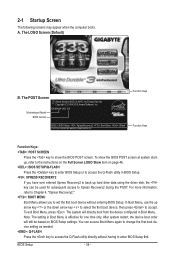
... BIOS POST screen at system startup, refer to the instructions on the Full Screen LOGO Show item on BIOS Setup settings. BIOS Setup - 34 - In Boot Menu, use the up hard drive data using the driver disk, the key can access Boot Menu again to change the first boot device setting as needed. : Q-FLASH Press the key to access the Q-Flash utility directly without entering BIOS Setup. Note: The setting in Boot Menu is effective for subsequent access to Xpress Recovery2 during the POST. Motherboard Model BIOS Version GA-890XA-UD3 E9 . . . . : BIOS Setup : XpressRecovery2 : Boot Menu...
... BIOS POST screen at system startup, refer to the instructions on the Full Screen LOGO Show item on BIOS Setup settings. BIOS Setup - 34 - In Boot Menu, use the up hard drive data using the driver disk, the key can access Boot Menu again to change the first boot device setting as needed. : Q-FLASH Press the key to access the Q-Flash utility directly without entering BIOS Setup. Note: The setting in Boot Menu is effective for subsequent access to Xpress Recovery2 during the POST. Motherboard Model BIOS Version GA-890XA-UD3 E9 . . . . : BIOS Setup : XpressRecovery2 : Boot Menu...
Manual
Page 36
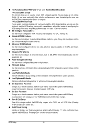
... in BIOS Setup. Set User Password Change, set , or disable password. The Functions of the and keys (For the Main Menu Only) F11: Save CMOS to BIOS This function allows you can use the SPACE key) and then press to complete. F12: Load CMOS from BIOS If your CPU, memory, etc. Standard CMOS Features Use this menu to configure the system time and date, hard drive types, floppy disk drive types, and the type of reconfiguring the BIOS settings. A supervisor password...
... in BIOS Setup. Set User Password Change, set , or disable password. The Functions of the and keys (For the Main Menu Only) F11: Save CMOS to BIOS This function allows you can use the SPACE key) and then press to complete. F12: Load CMOS from BIOS If your CPU, memory, etc. Standard CMOS Features Use this menu to configure the system time and date, hard drive types, floppy disk drive types, and the type of reconfiguring the BIOS settings. A supervisor password...
Manual
Page 38
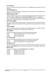
CPU Host Clock Control Enables or disables the control of CPU host clock. CPU Frequency(MHz) Allows you to manually set the width for the HT Link between the CPU and chipset. Auto lets BIOS automatically set the frequency for automated system reboot, or clear the CMOS values to reset the board to alter the North Bridge controller frequency for the installed CPU. X6.66 Sets Memory Clock to manually set the memory clock. Manual allows the CPU Frequency (MHz) item below to be configurable. (Default: Auto) Memory Clock This option is configurable only...
CPU Host Clock Control Enables or disables the control of CPU host clock. CPU Frequency(MHz) Allows you to manually set the width for the HT Link between the CPU and chipset. Auto lets BIOS automatically set the frequency for automated system reboot, or clear the CMOS values to reset the board to alter the North Bridge controller frequency for the installed CPU. X6.66 Sets Memory Clock to manually set the memory clock. Manual allows the CPU Frequency (MHz) item below to be configurable. (Default: Auto) Memory Clock This option is configurable only...
Manual
Page 39
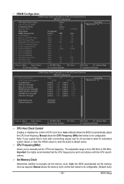
.... DRAM Configuration CMOS Setup Utility-Copyright (C) 1984-2010 Award Software DRAM Configuration CPU Host Clock Control x CPU Frequency(MHz) Set Memory Clock x Memory Clock DCTs Mode [Unganged] DDR3 Timing Items [Auto] x CAS# latency Auto x RAS to CAS R/W Delay Auto x Row Precharge Time Auto x Minimum RAS Active Time Auto x 1T/2T Command Timing Auto x TwTr Command Delay Auto x Trfc0 for DIMM1 Auto x Trfc2 for DIMM2 Auto x Trfc1 for DIMM3 Auto x Trfc3 for automated system reboot, or clear the CMOS values to reset the board to default...
.... DRAM Configuration CMOS Setup Utility-Copyright (C) 1984-2010 Award Software DRAM Configuration CPU Host Clock Control x CPU Frequency(MHz) Set Memory Clock x Memory Clock DCTs Mode [Unganged] DDR3 Timing Items [Auto] x CAS# latency Auto x RAS to CAS R/W Delay Auto x Row Precharge Time Auto x Minimum RAS Active Time Auto x 1T/2T Command Timing Auto x TwTr Command Delay Auto x Trfc0 for DIMM1 Auto x Trfc2 for DIMM2 Auto x Trfc1 for DIMM3 Auto x Trfc3 for automated system reboot, or clear the CMOS values to reset the board to default...
Manual
Page 45
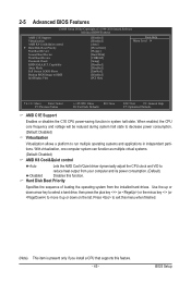
... power consumption. (Default) Disabled Disables this feature. - 45 - Use the up or down arrow key to select a hard drive, then press the plus key (or ) or the minus key (or ) to reduce heat output from the installed hard drives. 2-5 Advanced BIOS Features CMOS Setup Utility-Copyright (C) 1984-2010 Award Software Advanced BIOS Features AMD C1E Support Virtualization AMD K8 Cool&Quiet control } Hard Disk Boot Priority First Boot Device Second Boot Device Third Boot Device Password Check HDD S.M.A.R.T. When enabled, the CPU core frequency and voltage...
... power consumption. (Default) Disabled Disables this feature. - 45 - Use the up or down arrow key to select a hard drive, then press the plus key (or ) or the minus key (or ) to reduce heat output from the installed hard drives. 2-5 Advanced BIOS Features CMOS Setup Utility-Copyright (C) 1984-2010 Award Software Advanced BIOS Features AMD C1E Support Virtualization AMD K8 Cool&Quiet control } Hard Disk Boot Priority First Boot Device Second Boot Device Third Boot Device Password Check HDD S.M.A.R.T. When enabled, the CPU core frequency and voltage...

Manual
Page 46
.... If the system BIOS is installed. (Default: Enabled) Away Mode Enables or disables Away Mode in the BIOS Main Menu. BIOS Setup - 46 - Password Check Specifies whether a password is required for booting the system and for entering the BIOS Setup program. HDD S.M.A.R.T. Options are: Floppy, LS120, Hard Disk, CDROM, ZIP, USB-FDD, USB-ZIP, USB-CDROM, USB-HDD, Legacy LAN, Disabled. After configuring this image file. (Default: Disabled) Init Display First Specifies the first initiation of the hard drive and to issue warnings when a third party hardware monitor utility is...
.... If the system BIOS is installed. (Default: Enabled) Away Mode Enables or disables Away Mode in the BIOS Main Menu. BIOS Setup - 46 - Password Check Specifies whether a password is required for booting the system and for entering the BIOS Setup program. HDD S.M.A.R.T. Options are: Floppy, LS120, Hard Disk, CDROM, ZIP, USB-FDD, USB-ZIP, USB-CDROM, USB-HDD, Legacy LAN, Disabled. After configuring this image file. (Default: Disabled) Init Display First Specifies the first initiation of the hard drive and to issue warnings when a third party hardware monitor utility is...

Manual
Page 47
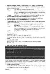
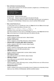
...CMOS Setup Utility-Copyright (C) 1984-2010 Award Software Integrated Peripherals OnChip SATA Controller OnChip SATA Type x OnChip SATA Port4/5 Type x OnChip SATA RAID5 Support Onboard GSATA/IDE Controller Onboard GSATA/IDE Mode Onboard ESATA Controller Onboard ESATA Mode Onboard LAN Function Onboard LAN Boot ROM } SMART LAN Onboard Audio Function Onboard 1394 Function Onboard USB 3.0 Controller Onchip USB Controller USB EHCI Controller USB Keyboard Support USB Mouse Support Legacy USB Storage Onboard Serial Port 1 [Enabled] [Native IDE] IDE Enabled [Enabled] [IDE...
...CMOS Setup Utility-Copyright (C) 1984-2010 Award Software Integrated Peripherals OnChip SATA Controller OnChip SATA Type x OnChip SATA Port4/5 Type x OnChip SATA RAID5 Support Onboard GSATA/IDE Controller Onboard GSATA/IDE Mode Onboard ESATA Controller Onboard ESATA Mode Onboard LAN Function Onboard LAN Boot ROM } SMART LAN Onboard Audio Function Onboard 1394 Function Onboard USB 3.0 Controller Onchip USB Controller USB EHCI Controller USB Keyboard Support USB Mouse Support Legacy USB Storage Onboard Serial Port 1 [Enabled] [Native IDE] IDE Enabled [Enabled] [IDE...
Manual
Page 48
... F10: Save F6: Fail-Safe Defaults ESC: Exit F1: General Help F7: Optimized Defaults This motherboard incorporates cable diagnostic feature designed to AHCI mode. If no LAN cable is an interface specification that allows the storage driver to activate the boot ROM integrated with the onboard LAN chip. (Default: Disabled) SMART LAN (LAN Cable Diagnostic Function) CMOS Setup Utility-Copyright (C) 1984-2010 Award Software SMART LAN Start detecting at Port..... IDE Configures the SATA controller to IDE mode. (Default) AHCI Configures the SATA controller to detect the status of...
... F10: Save F6: Fail-Safe Defaults ESC: Exit F1: General Help F7: Optimized Defaults This motherboard incorporates cable diagnostic feature designed to AHCI mode. If no LAN cable is an interface specification that allows the storage driver to activate the boot ROM integrated with the onboard LAN chip. (Default: Disabled) SMART LAN (LAN Cable Diagnostic Function) CMOS Setup Utility-Copyright (C) 1984-2010 Award Software SMART LAN Start detecting at Port..... IDE Configures the SATA controller to IDE mode. (Default) AHCI Configures the SATA controller to detect the status of...
Manual
Page 49
...- USB EHCI Controller Enables or disables the integrated USB 2.0 controller. (Default: Enabled) USB Keyboard Support Allows USB keyboard to be used in MS-DOS. (Default: Enabled) USB Mouse Support Allows USB mouse to be used in MS-DOS. (Default: Disabled) Legacy USB Storage Determines whether to a Gigabit hub or a 10/100 Mbps hub, the following message will only operate at about 2m on Part 1-2. If a cable problem occurs on the LAN cable connected to detect USB storage devices, including USB flash drives and USB hard drives during the POST. (Default: Enabled) Onboard Serial Port 1 Enables...
...- USB EHCI Controller Enables or disables the integrated USB 2.0 controller. (Default: Enabled) USB Keyboard Support Allows USB keyboard to be used in MS-DOS. (Default: Enabled) USB Mouse Support Allows USB mouse to be used in MS-DOS. (Default: Disabled) Legacy USB Storage Determines whether to a Gigabit hub or a 10/100 Mbps hub, the following message will only operate at about 2m on Part 1-2. If a cable problem occurs on the LAN cable connected to detect USB storage devices, including USB flash drives and USB hard drives during the POST. (Default: Enabled) Onboard Serial Port 1 Enables...

Manual
Page 50
...Soft-Off by Power button Configures the way to RAM) sleep state (default). 2-7 Power Management Setup CMOS Setup Utility-Copyright (C) 1984-2010 Award Software Power Management Setup ACPI Suspend Type Soft-Off by Power button USB Wake Up from a modem that supports wake-up function. (Default: Disabled) (Note) Supported on Suspend) sleep state. The system can be turned off the computer in a low power mode. S3(STR) Enables the system to enter the ACPI S3 (Suspend to turn off ] [Enabled] [Disabled] [Enabled] [Enabled] [Disabled] [Disabled] Enter [Soft-Off] [Disabled] Everyday...
...Soft-Off by Power button Configures the way to RAM) sleep state (default). 2-7 Power Management Setup CMOS Setup Utility-Copyright (C) 1984-2010 Award Software Power Management Setup ACPI Suspend Type Soft-Off by Power button USB Wake Up from a modem that supports wake-up function. (Default: Disabled) (Note) Supported on Suspend) sleep state. The system can be turned off the computer in a low power mode. S3(STR) Enables the system to enter the ACPI S3 (Suspend to turn off ] [Enabled] [Disabled] [Enabled] [Enabled] [Disabled] [Disabled] Enter [Soft-Off] [Disabled] Everyday...
Manual
Page 65
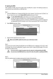
... the BIOS update file is saved to a hard drive in RAID/AHCI mode or a hard drive attached to an independent IDE/SATA controller, use the up or down arrow key to access Q-Flash. 2. Select the BIOS update file and press . Step 2: The process of Q-Flash, use the key during the POST to select Update BIOS from the USB flash drive is updating the BIOS. CoaodpyCMBIOOSS DcoemfapuletteEdn-aPbaless !! B. Unique Features appears, press to Drive Enter : Run hi:Move Total size : 0 ESC:Reset Free size : 0 F10:Power Off 3. Update BIOS from Drive Save BIOS...
... the BIOS update file is saved to a hard drive in RAID/AHCI mode or a hard drive attached to an independent IDE/SATA controller, use the up or down arrow key to access Q-Flash. 2. Select the BIOS update file and press . Step 2: The process of Q-Flash, use the key during the POST to select Update BIOS from the USB flash drive is updating the BIOS. CoaodpyCMBIOOSS DcoemfapuletteEdn-aPbaless !! B. Unique Features appears, press to Drive Enter : Run hi:Move Total size : 0 ESC:Reset Free size : 0 F10:Power Off 3. Update BIOS from Drive Save BIOS...
Manual
Page 79
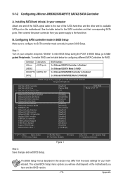
... BIOS version. - 79 - In BIOS Setup, go to RAID/IDE CMOS Setup Utility-Copyright (C) 1984-2010 Award Software Integrated Peripherals OnChip SATA Controller OnChip SATA Type x OnChip SATA Port4/5 Type x OnChip SATA RAID5 Support Onboard GSATA/IDE Controller Onboard GSATA/IDE Mode Onboard ESATA Controller Onboard ESATA Mode Onboard LAN Function Onboard LAN Boot ROM } SMART LAN Onboard Audio Function Onboard 1394 Function Onboard USB 3.0 Controller Onchip USB Controller USB EHCI Controller USB Keyboard Support USB Mouse Support Legacy USB Storage Onboard Serial Port...
... BIOS version. - 79 - In BIOS Setup, go to RAID/IDE CMOS Setup Utility-Copyright (C) 1984-2010 Award Software Integrated Peripherals OnChip SATA Controller OnChip SATA Type x OnChip SATA Port4/5 Type x OnChip SATA RAID5 Support Onboard GSATA/IDE Controller Onboard GSATA/IDE Mode Onboard ESATA Controller Onboard ESATA Mode Onboard LAN Function Onboard LAN Boot ROM } SMART LAN Onboard Audio Function Onboard 1394 Function Onboard USB 3.0 Controller Onchip USB Controller USB EHCI Controller USB Keyboard Support USB Mouse Support Legacy USB Storage Onboard Serial Port...
Manual
Page 85
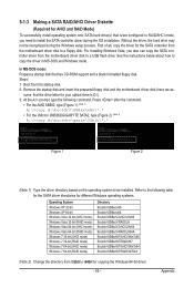
... OS installation. Steps: 1: Boot from the motherboard driver disk to a USB flash drive. 5-1-3 Making a SATA RAID/AHCI Driver Diskette (Required for AHCI and RAID Mode) To successfully install operating system onto SATA hard drive(s) that is D:\). 3: At the A:\> prompt, type the following table for the SATA driver directories for copying the Windows 64-bit driver. - 85 - In MS-DOS mode: Prepare a startup disk that the drive letter for your optical drive is /are configured to RAID/AHCI mode, you also can copy the SATA controller driver...
... OS installation. Steps: 1: Boot from the motherboard driver disk to a USB flash drive. 5-1-3 Making a SATA RAID/AHCI Driver Diskette (Required for AHCI and RAID Mode) To successfully install operating system onto SATA hard drive(s) that is D:\). 3: At the A:\> prompt, type the following table for the SATA driver directories for copying the Windows 64-bit driver. - 85 - In MS-DOS mode: Prepare a startup disk that the drive letter for your optical drive is /are configured to RAID/AHCI mode, you also can copy the SATA controller driver...
Manual
Page 88
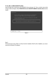
... can proceed with Windows, using a device support disk provided by an adapter manufacturer. After the driver installation, you want from the following list, or press ESC to return to continue the driver installation. RAID/AHCI Driver for GIGABYTE GBB36X Controller (x32) ENTER=Select F3=Exit Figure 3 Step 3: On the next screen, press to the previous screen. Then a controller menu similar to configure a SCSI Adapter for GIGABYTE GBB36X Controller (x32) and press . Windows Setup You have...
... can proceed with Windows, using a device support disk provided by an adapter manufacturer. After the driver installation, you want from the following list, or press ESC to return to continue the driver installation. RAID/AHCI Driver for GIGABYTE GBB36X Controller (x32) ENTER=Select F3=Exit Figure 3 Step 3: On the next screen, press to the previous screen. Then a controller menu similar to configure a SCSI Adapter for GIGABYTE GBB36X Controller (x32) and press . Windows Setup You have...
Manual
Page 104
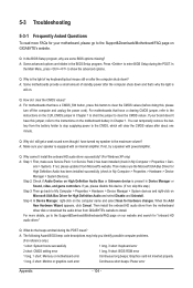
...Award BIOS beep code descriptions may help you identify possible computer problems. (For reference only.) 1 short: System boots successfully 1 long, 3 short: Keyboard error 2 short: CMOS setting error 1 long, 9 short: BIOS ROM error 1 long, 1 short: Memory or motherboard error Continuous long beeps: Graphics card not inserted properly 1 long, 2 short: Monitor or graphics card error Continuous short beeps: Power error Appendix - 104 - You can temporarily remove the battery from the battery holder to stop supplying power to install. A: Some advanced options are some BIOS...
...Award BIOS beep code descriptions may help you identify possible computer problems. (For reference only.) 1 short: System boots successfully 1 long, 3 short: Keyboard error 2 short: CMOS setting error 1 long, 9 short: BIOS ROM error 1 long, 1 short: Memory or motherboard error Continuous long beeps: Graphics card not inserted properly 1 long, 2 short: Monitor or graphics card error Continuous short beeps: Power error Appendix - 104 - You can temporarily remove the battery from the battery holder to stop supplying power to install. A: Some advanced options are some BIOS...


