Manual
Page 3
...copyright laws and is 1.0. No part of this manual is protected by GIGABYTE without GIGABYTE's prior written permission. For product-related information, check on our website at: http://www.gigabyte.com.tw Identifying Your Motherboard Revision The revision number on our website.... before updating motherboard BIOS, drivers, or when looking for technical information. For detailed product information, carefully read the Quick Installation Guide included with the product. The trademarks mentioned in this manual are legally registered to assist in this manual may be...
...copyright laws and is 1.0. No part of this manual is protected by GIGABYTE without GIGABYTE's prior written permission. For product-related information, check on our website at: http://www.gigabyte.com.tw Identifying Your Motherboard Revision The revision number on our website.... before updating motherboard BIOS, drivers, or when looking for technical information. For detailed product information, carefully read the Quick Installation Guide included with the product. The trademarks mentioned in this manual are legally registered to assist in this manual may be...
Manual
Page 4
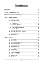
Table of Contents Box Contents...6 Optional Items...6 GA-890XA-UD3 Motherboard Layout 7 GA-890XA-UD3 Motherboard Block Diagram 8 Chapter 1 Hardware Installation 9 1-1 Installation Precautions 9 1-2 Product Specifications 10 1-3 Installing the CPU and CPU Cooler 13 1-3-1 Installing the CPU 13 1-3-2 Installing the CPU Cooler 15 1-4 Installing the Memory 16 1-4-1 Dual Channel Memory Configuration 16 1-4-2 Installing a Memory 17 1-5 Installing an Expansion Card 18 1-6 Setup of the ATI CrossFireX™...
Table of Contents Box Contents...6 Optional Items...6 GA-890XA-UD3 Motherboard Layout 7 GA-890XA-UD3 Motherboard Block Diagram 8 Chapter 1 Hardware Installation 9 1-1 Installation Precautions 9 1-2 Product Specifications 10 1-3 Installing the CPU and CPU Cooler 13 1-3-1 Installing the CPU 13 1-3-2 Installing the CPU Cooler 15 1-4 Installing the Memory 16 1-4-1 Dual Channel Memory Configuration 16 1-4-2 Installing a Memory 17 1-5 Installing an Expansion Card 18 1-6 Setup of the ATI CrossFireX™...
Manual
Page 5
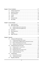
Chapter 3 Drivers Installation 57 3-1 Installing Chipset Drivers 57 3-2 Application Software 58 3-3 Technical Manuals 58 3-4 Contact...59 3-5 System...59 3-6 Download Center 60 3-7 New Utilities...60 Chapter 4 Unique... 5 Appendix...73 5-1 Configuring SATA Hard Drive(s 73 5-1-1 Configuring AMD SB850 SATA Controller 73 5-1-2 Configuring JMicron JMB362/GIGABYTE SATA2 SATA Controller 79 5-1-3 Making a SATA RAID/AHCI Driver Diskette 85 5-1-4 Installing the SATA RAID/AHCI Driver and Operating System 87 5-2 Configuring Audio Input and Output 96 5-2-1 Configuring 2/4/5.1/7.1-Channel Audio ...
Chapter 3 Drivers Installation 57 3-1 Installing Chipset Drivers 57 3-2 Application Software 58 3-3 Technical Manuals 58 3-4 Contact...59 3-5 System...59 3-6 Download Center 60 3-7 New Utilities...60 Chapter 4 Unique... 5 Appendix...73 5-1 Configuring SATA Hard Drive(s 73 5-1-1 Configuring AMD SB850 SATA Controller 73 5-1-2 Configuring JMicron JMB362/GIGABYTE SATA2 SATA Controller 79 5-1-3 Making a SATA RAID/AHCI Driver Diskette 85 5-1-4 Installing the SATA RAID/AHCI Driver and Operating System 87 5-2 Configuring Audio Input and Output 96 5-2-1 Configuring 2/4/5.1/7.1-Channel Audio ...

Manual
Page 6
... cable (Part No. 12CR1-1SPDIN-0*R) COM port cable (Part No. 12CF1-1CM001-3*R) - 6 - The box contents are for reference only. Box Contents GA-890XA-UD3 motherboard Motherboard driver disk User's Manual Quick Installation Guide One IDE cable Four SATA 3Gb/s cables I/O Shield • The box contents above are subject to change without notice. • The...
... cable (Part No. 12CR1-1SPDIN-0*R) COM port cable (Part No. 12CF1-1CM001-3*R) - 6 - The box contents are for reference only. Box Contents GA-890XA-UD3 motherboard Motherboard driver disk User's Manual Quick Installation Guide One IDE cable Four SATA 3Gb/s cables I/O Shield • The box contents above are subject to change without notice. • The...
Manual
Page 8
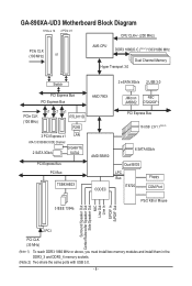
GA-890XA-UD3 Motherboard Block Diagram 1 PCIe x 16 2 PCIe x 8 CPU CLK+/- (200 MHz) PCIe CLK (100 MHz) or AM3 CPU ... (100 MHz) x1 x1 x1 RTL8111D RJ45 3 PCI Express x1 LAN ATA-133/100/66/33 IDE Channel 2 SATA 3Gb/s GIGABYTE SATA2 PCI Express Bus PCI Bus TSB43AB23 AMD 790X AMD SB850 CODEC JMicron NEC JMB362 D720200F1 PCI Express Bus 16 USB 2.0/1.1(Note 2) ... Out 2 PCI 2 PCI PCI CLK (33 MHz) (Note 1) To reach DDR3 1866 MHz or above, you must install two memory modules and install them in the DDR3_3 and DDR3_4 memory sockets. (Note 2) Two share the same ports with USB 3.0. - 8 -
GA-890XA-UD3 Motherboard Block Diagram 1 PCIe x 16 2 PCIe x 8 CPU CLK+/- (200 MHz) PCIe CLK (100 MHz) or AM3 CPU ... (100 MHz) x1 x1 x1 RTL8111D RJ45 3 PCI Express x1 LAN ATA-133/100/66/33 IDE Channel 2 SATA 3Gb/s GIGABYTE SATA2 PCI Express Bus PCI Bus TSB43AB23 AMD 790X AMD SB850 CODEC JMicron NEC JMB362 D720200F1 PCI Express Bus 16 USB 2.0/1.1(Note 2) ... Out 2 PCI 2 PCI PCI CLK (33 MHz) (Note 1) To reach DDR3 1866 MHz or above, you must install two memory modules and install them in the DDR3_3 and DDR3_4 memory sockets. (Note 2) Two share the same ports with USB 3.0. - 8 -
Manual
Page 9
... certified computer technician. - 9 - If you are connected tightly and securely. • When handling the motherboard, avoid touching any installation steps or have it on top of an antistatic pad or within an electrostatic shielding container. • Before unplugging the power supply cable... from the power outlet before installing or removing the motherboard or other hardware components. • When connecting hardware components to the internal connectors on the motherboard...
... certified computer technician. - 9 - If you are connected tightly and securely. • When handling the motherboard, avoid touching any installation steps or have it on top of an antistatic pad or within an electrostatic shielding container. • Before unplugging the power supply cable... from the power outlet before installing or removing the motherboard or other hardware components. • When connecting hardware components to the internal connectors on the motherboard...
Manual
Page 10
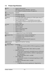
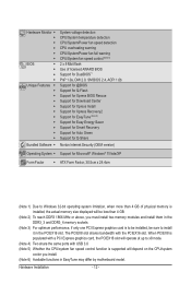
...- 1-2 Product Specifications CPU Support for AM3 processors: AMD Phenom™ II processor/ AMD Athlon™ II processor/ (Go to GIGABYTE's website for the latest CPU support list.) Hyper Transport Bus 5200 MT/s Chipset Memory Audio... - 6 x SATA 6Gb/s connectors (SATA3_0~SATA3_5) supporting up to 1 floppy disk drive Hardware Installation - 10 - Support for SATA RAID 0, RAID 1, RAID 5, RAID 10, and JBOD GIGABYTE SATA2 chip: - 1 x IDE connector supporting ATA-133/100/66/33 and up to 2...
...- 1-2 Product Specifications CPU Support for AM3 processors: AMD Phenom™ II processor/ AMD Athlon™ II processor/ (Go to GIGABYTE's website for the latest CPU support list.) Hyper Transport Bus 5200 MT/s Chipset Memory Audio... - 6 x SATA 6Gb/s connectors (SATA3_0~SATA3_5) supporting up to 1 floppy disk drive Hardware Installation - 10 - Support for SATA RAID 0, RAID 1, RAID 5, RAID 10, and JBOD GIGABYTE SATA2 chip: - 1 x IDE connector supporting ATA-133/100/66/33 and up to 2...
Manual
Page 11
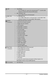
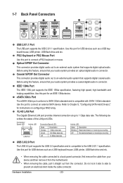
... w 8 x USB 2.0/1.1 ports w 2 x USB 3.0/2.0 ports w 1 x RJ-45 port w 6 x audio jacks (Center/Subwoofer Speaker Out/Rear Speaker Out/ Side Speaker Out/Line In/Line Out/Microphone) I . Hardware Installation
... w 8 x USB 2.0/1.1 ports w 2 x USB 3.0/2.0 ports w 1 x RJ-45 port w 6 x audio jacks (Center/Subwoofer Speaker Out/Rear Speaker Out/ Side Speaker Out/Line In/Line Out/Microphone) I . Hardware Installation
Manual
Page 12
...2.0, SM BIOS 2.4, ACPI 1.0b Support for @BIOS Support for Q-Flash Support for Xpress BIOS Rescue Support for Download Center Support for Xpress Install Support for Xpress Recovery2 Support for EasyTune (Note 6) Support for Easy Energy Saver Support for Smart Recovery Support for Auto Green Support for ... graphics card is supported will be less than 4 GB. (Note 2) To reach DDR3 1866 MHz or above, you install. (Note 6) Available functions in the PCIEX16 slot. Hardware Installation - 12 - The PCIEX8 slot shares bandwidth with USB 3.0 (Note 5) Whether the CPU/system fan speed control function...
...2.0, SM BIOS 2.4, ACPI 1.0b Support for @BIOS Support for Q-Flash Support for Xpress BIOS Rescue Support for Download Center Support for Xpress Install Support for Xpress Recovery2 Support for EasyTune (Note 6) Support for Easy Energy Saver Support for Smart Recovery Support for Auto Green Support for ... graphics card is supported will be less than 4 GB. (Note 2) To reach DDR3 1866 MHz or above, you install. (Note 6) Available functions in the PCIEX16 slot. Hardware Installation - 12 - The PCIEX8 slot shares bandwidth with USB 3.0 (Note 5) Whether the CPU/system fan speed control function...
Manual
Page 13
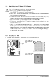
...standard requirements for the latest CPU support list.) • Always turn off the computer and unplug the power cord from the power outlet before installing the CPU to prevent hardware damage. • Locate the pin one (denoted by a small triangle) of the CPU may locate the ...not recommended that the motherboard supports the CPU. (Go to GIGABYTE's website for the peripherals. A Small Triangle Mark Denotes Pin One of the CPU. 1-3 Installing the CPU and CPU Cooler Read the following guidelines before you begin to install the CPU: • Make sure that the system bus frequency...
...standard requirements for the latest CPU support list.) • Always turn off the computer and unplug the power cord from the power outlet before installing the CPU to prevent hardware damage. • Locate the pin one (denoted by a small triangle) of the CPU may locate the ...not recommended that the motherboard supports the CPU. (Go to GIGABYTE's website for the peripherals. A Small Triangle Mark Denotes Pin One of the CPU. 1-3 Installing the CPU and CPU Cooler Read the following guidelines before you begin to install the CPU: • Make sure that the system bus frequency...
Manual
Page 14
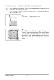
CPU Socket Locking Lever Step 1: Completely lift up the CPU socket locking lever. Follow the steps below to correctly install the CPU into the motherboard CPU socket. • Before installing the CPU, make sure to turn off the computer and unplug the power cord from the power outlet to prevent... (small triangle marking) with the triangle mark on the middle of the CPU, lowering the locking lever and latching it into the socket. Hardware Installation - 14 - The CPU cannot fit in if oriented incorrectly. Step 2: Align the CPU pin one finger down on the CPU socket and gently...
CPU Socket Locking Lever Step 1: Completely lift up the CPU socket locking lever. Follow the steps below to correctly install the CPU into the motherboard CPU socket. • Before installing the CPU, make sure to turn off the computer and unplug the power cord from the power outlet to prevent... (small triangle marking) with the triangle mark on the middle of the CPU, lowering the locking lever and latching it into the socket. Hardware Installation - 14 - The CPU cannot fit in if oriented incorrectly. Step 2: Align the CPU pin one finger down on the CPU socket and gently...
Manual
Page 15
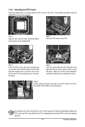
...mounting lug on the surface of the installed CPU. Inadequately removing the CPU cooler may adhere to the CPU. 1-3-2 Installing the CPU Cooler Follow the steps below to correctly install the CPU cooler on the CPU. (The following procedure uses the GIGABYTE cooler as the picture above shows)... to lock into place. (Refer to your CPU cooler installation manual for instructions on installing the cooler.) Step 5: Finally, attach ...
...mounting lug on the surface of the installed CPU. Inadequately removing the CPU cooler may adhere to the CPU. 1-3-2 Installing the CPU Cooler Follow the steps below to correctly install the CPU cooler on the CPU. (The following procedure uses the GIGABYTE cooler as the picture above shows)... to lock into place. (Refer to your CPU cooler installation manual for instructions on installing the cooler.) Step 5: Finally, attach ...
Manual
Page 16
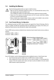
... the latest supported memory speeds and momery moudles.) • Always turn off the computer and unplug the power cord from the power outlet before installing the memory to GIGABYTE's website for optimum performance. It is recommended that memory of the memory. Enabling Dual Channel memory mode will automatically detect the specifications and...
... the latest supported memory speeds and momery moudles.) • Always turn off the computer and unplug the power cord from the power outlet before installing the memory to GIGABYTE's website for optimum performance. It is recommended that memory of the memory. Enabling Dual Channel memory mode will automatically detect the specifications and...
Manual
Page 17
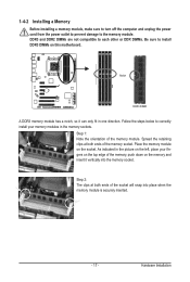
... memory module. Step 2: The clips at both ends of the memory socket. Place the memory module on the top edge of the memory module. Hardware Installation 1-4-2 Installing a Memory Before installing a memory module, make sure to turn off the computer and unplug the power cord from the power outlet to prevent damage to...
... memory module. Step 2: The clips at both ends of the memory socket. Place the memory module on the top edge of the memory module. Hardware Installation 1-4-2 Installing a Memory Before installing a memory module, make sure to turn off the computer and unplug the power cord from the power outlet to prevent damage to...
Manual
Page 18
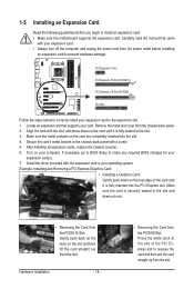
...Slot: Press the white latch at the end of the card until it is securely seated in your expansion card(s). 7. Hardware Installation - 18 - • Removing the Card from the slot. Carefully read the manual that supports your computer. Remove the metal...came with a screw. 5. 1-5 Installing an Expansion Card Read the following guidelines before installing an expansion card to install an expansion card: • Make sure the motherboard supports the expansion card. Example: Installing and Removing a PCI Express Graphics Card: • Installing a Graphics Card: Gently push down ...
...Slot: Press the white latch at the end of the card until it is securely seated in your expansion card(s). 7. Hardware Installation - 18 - • Removing the Card from the slot. Carefully read the manual that supports your computer. Remove the metal...came with a screw. 5. 1-5 Installing an Expansion Card Read the following guidelines before installing an expansion card to install an expansion card: • Make sure the motherboard supports the expansion card. Example: Installing and Removing a PCI Express Graphics Card: • Installing a Graphics Card: Gently push down ...
Manual
Page 19
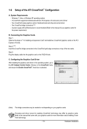
Connecting the Graphics Cards Step 1: Observe the steps in "1-5 Installing an Expansion Card" and install two CrossFireX graphics cards on the PCIEX16 slot. C. Hardware Installation Windows 7, Vista, or Windows XP operating system - Two CrossFireX-ready graphics cards of the ATI CrossFireX™ ...Refer to the manual that came with two PCI Express x16 slots and correct driver - Configuring the Graphics Card Driver After installing the graphics card driver in the CrossFireX gold edge connectors on your graphics cards for enabling CrossFireX technology may be needed or...
Connecting the Graphics Cards Step 1: Observe the steps in "1-5 Installing an Expansion Card" and install two CrossFireX graphics cards on the PCIEX16 slot. C. Hardware Installation Windows 7, Vista, or Windows XP operating system - Two CrossFireX-ready graphics cards of the ATI CrossFireX™ ...Refer to the manual that came with two PCI Express x16 slots and correct driver - Configuring the Graphics Card Driver After installing the graphics card driver in the CrossFireX gold edge connectors on your graphics cards for enabling CrossFireX technology may be needed or...
Manual
Page 20
Hardware Installation - 20 - Optical S/PDIF Out Connector This connector provides digital audio out to an external audio system that supports digital optical audio. Coaxial S/PDIF Out Connector ...
Hardware Installation - 20 - Optical S/PDIF Out Connector This connector provides digital audio out to an external audio system that supports digital optical audio. Coaxial S/PDIF Out Connector ...

Manual
Page 21
... to this audio jack for line in jack. Mic In Jack (Pink) The default Mic in devices such as an optical drive, walkman, etc. Hardware Installation Use this jack. Side Speaker Out Jack (Gray) Use this audio jack for a headphone or 2-channel speaker. In addition to the default speakers settings, the...
... to this audio jack for line in jack. Mic In Jack (Pink) The default Mic in devices such as an optical drive, walkman, etc. Hardware Installation Use this jack. Side Speaker Out Jack (Gray) Use this audio jack for a headphone or 2-channel speaker. In addition to the default speakers settings, the...

Manual
Page 22
Unplug the power cord from the power outlet to prevent damage to the devices. • After installing the device and before connecting external devices: • First make sure the device cable has been securely attached to turn off the devices and your ...) CLR_CMOS Read the following guidelines before turning on the computer, make sure your devices are compliant with the connectors you wish to connect. • Before installing the devices, be sure to the connector on the motherboard. Hardware...
Unplug the power cord from the power outlet to prevent damage to the devices. • After installing the device and before connecting external devices: • First make sure the device cable has been securely attached to turn off the devices and your ...) CLR_CMOS Read the following guidelines before turning on the computer, make sure your devices are compliant with the connectors you wish to connect. • Before installing the devices, be sure to the connector on the motherboard. Hardware...
Manual
Page 23
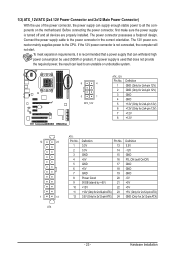
... supplies power to the power connector in the correct orientation. To meet expansion requirements, it is used that can lead to all devices are properly installed. Hardware Installation If a power supply is recommended that a power supply that does not provide the required power, the result can withstand high power consumption be used...
... supplies power to the power connector in the correct orientation. To meet expansion requirements, it is used that can lead to all devices are properly installed. Hardware Installation If a power supply is recommended that a power supply that does not provide the required power, the result can withstand high power consumption be used...


