
User Manual
Page 5
GA-7S748 Series AMD Socket A Processor Motherboard USER'S MANUAL AMD Athlon™ /Athlon™ XP / Duron™ SocketA ProcessorMotherboard Rev. 1003 12ME-7S748-1003
GA-7S748 Series AMD Socket A Processor Motherboard USER'S MANUAL AMD Athlon™ /Athlon™ XP / Duron™ SocketA ProcessorMotherboard Rev. 1003 12ME-7S748-1003

User Manual
Page 9
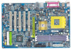
... I /O - 3 184-pin DDRsockets - Supports up to be continued...... - 5 - Supports DDR DRAM DDR266/DDR333/DDR400 - Socket Aprocessor AMD AthlonTM/AthlonTM XP/ DuronTM (K7) 128K L1 & 256K/64K L2 cache on die 200/266/333/400 MHz FSB and DDR bus speeds - System Voltage Detect - Introduction GA-7S748 Series Motherboard: GA-7S748 and GA-7S748-L - Supports 1.4GHz and faster -
... I /O - 3 184-pin DDRsockets - Supports up to be continued...... - 5 - Supports DDR DRAM DDR266/DDR333/DDR400 - Socket Aprocessor AMD AthlonTM/AthlonTM XP/ DuronTM (K7) 128K L1 & 256K/64K L2 cache on die 200/266/333/400 MHz FSB and DDR bus speeds - System Voltage Detect - Introduction GA-7S748 Series Motherboard: GA-7S748 and GA-7S748-L - Supports 1.4GHz and faster -

User Manual
Page 12
English Block Diagram AGP 4X/8X AGPCLK (66M Hz) 5 PCI RJ 45 (*) RTL82 01BL(*) K7 Socket A CPU CPUCLK+/- (100/133/166/200 MHz) System Bus 266/333/400 MHz DDR SiS 748 266/333/400 MHz ZCLK (66/133MHz) HCLK+/- (100/...) USBCLK (48MHz) 14.318 MHz 33 MHz CLK GEN ZCLK (66/133MHz) CPUCLK+/- (100/133/166/200MHz) AGPCLK (66MHz) HCLK+/- (100/133/166/200MHz) (*) For GA-7S748-L only. GA-7S748 Series Motherboard - 8 -
English Block Diagram AGP 4X/8X AGPCLK (66M Hz) 5 PCI RJ 45 (*) RTL82 01BL(*) K7 Socket A CPU CPUCLK+/- (100/133/166/200 MHz) System Bus 266/333/400 MHz DDR SiS 748 266/333/400 MHz ZCLK (66/133MHz) HCLK+/- (100/...) USBCLK (48MHz) 14.318 MHz 33 MHz CLK GEN ZCLK (66/133MHz) CPUCLK+/- (100/133/166/200MHz) AGPCLK (66MHz) HCLK+/- (100/133/166/200MHz) (*) For GA-7S748-L only. GA-7S748 Series Motherboard - 8 -

User Manual
Page 15
...processor, adhere to the following warning: 1.Please make sure the CPU type is supported by the motherboard. 2.If you do not match the CPU socket Pin 1 and CPU cut edge on the CPU upper corner. Please change the insert orientation. Hardware Installation Process Locate Pin 1 in the socketand ...look for a (golden) cut edge well, it will cause improper installation. Pull up the CPU socket lever andupto 90-degreeangle. 2. Then insert the CPU into the socket. - 11 - CPU Top View Socket Actuation Lever CPU Bottom View Pin1 indicator 1.
...processor, adhere to the following warning: 1.Please make sure the CPU type is supported by the motherboard. 2.If you do not match the CPU socket Pin 1 and CPU cut edge on the CPU upper corner. Please change the insert orientation. Hardware Installation Process Locate Pin 1 in the socketand ...look for a (golden) cut edge well, it will cause improper installation. Pull up the CPU socket lever andupto 90-degreeangle. 2. Then insert the CPU into the socket. - 11 - CPU Top View Socket Actuation Lever CPU Bottom View Pin1 indicator 1.

User Manual
Page 16
... plugged to the CPUfan connector,this completesthe installation. Press down the CPU socket lever and finish CPU installation. 2. Make sure the CPU fan is plugged in to the CPU fan connector, than installcomplete. Fastentheheatsinksupporting-base onto the CPUsocketon the mainboard. 4. GA-7S748 Series Motherboard - 12 - Please refer to the following warning: 1. English Step1...
... plugged to the CPUfan connector,this completesthe installation. Press down the CPU socket lever and finish CPU installation. 2. Make sure the CPU fan is plugged in to the CPU fan connector, than installcomplete. Fastentheheatsinksupporting-base onto the CPUsocketon the mainboard. 4. GA-7S748 Series Motherboard - 12 - Please refer to the following warning: 1. English Step1...

User Manual
Page 17
...fit in one direction due to the following warning: 1. Hardware Installation Process The motherboard has 3 dual inline memory module(DIMM)sockets. To install the memory module, just push it vertically into the DIMM Slot. Notch DDR Support Unbuffered DDR DIMM Sizes type...(4Mx16x4 banks) - 13 - When RAM_LEDis ON, do not install / remove DIMM from socket. 2. Wrong orientation will cause improper installation. Please note that the DIMM module can varybetween sockets. The BIOS willautomatically detects memory type and size. Please change the insertorientation. English Step 2:...
...fit in one direction due to the following warning: 1. Hardware Installation Process The motherboard has 3 dual inline memory module(DIMM)sockets. To install the memory module, just push it vertically into the DIMM Slot. Notch DDR Support Unbuffered DDR DIMM Sizes type...(4Mx16x4 banks) - 13 - When RAM_LEDis ON, do not install / remove DIMM from socket. 2. Wrong orientation will cause improper installation. Please note that the DIMM module can varybetween sockets. The BIOS willautomatically detects memory type and size. Please change the insertorientation. English Step 2:...
User Manual
Page 84
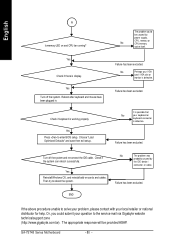
...socket itself. Yes Check if there is defective. Reboot after keyboard and mouse have been plugged in. Then try to enter BIOS setup. GA-7S748 Series Motherboard - 80 - Failure has been excluded. Check if keyboard is defective. END If the above procedure unable to the service mail via Gigabyte... website technical support zone (http://www.gigabyte.com.tw). The appropriate ...
...socket itself. Yes Check if there is defective. Reboot after keyboard and mouse have been plugged in. Then try to enter BIOS setup. GA-7S748 Series Motherboard - 80 - Failure has been excluded. Check if keyboard is defective. END If the above procedure unable to the service mail via Gigabyte... website technical support zone (http://www.gigabyte.com.tw). The appropriate ...

