Manual
Page 7
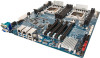
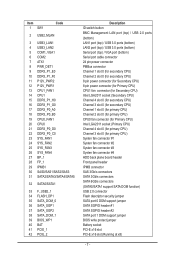
... CPU) Intel LGA2011 socket (Primary CPU) Channel 4 slot 0 (for primary CPU) Channel 3 slot 0 (for primary CPU) Systen fan connector #1 Systen fan connector #2 Systen fan connector #3 Systen fan connector #4 HDD back plane board header Front panel header IPMB connector SAS 3Gb/s connectors SATA 3Gb/s connectors SATA 6Gb/s connectors (SATA0/SATA1 support SATA DOM function) USB 2.0 connector Flash descriptor security jumper SATA port 0 DOM support jumper SATA SGPIO header #1 SATA SGPIO header #2 SATA port 1 DOM support jumper BIOS write protect jumper Battery socket PCI-E x16 slot PCI-E x16 slot...
... CPU) Intel LGA2011 socket (Primary CPU) Channel 4 slot 0 (for primary CPU) Channel 3 slot 0 (for primary CPU) Systen fan connector #1 Systen fan connector #2 Systen fan connector #3 Systen fan connector #4 HDD back plane board header Front panel header IPMB connector SAS 3Gb/s connectors SATA 3Gb/s connectors SATA 6Gb/s connectors (SATA0/SATA1 support SATA DOM function) USB 2.0 connector Flash descriptor security jumper SATA port 0 DOM support jumper SATA SGPIO header #1 SATA SGPIO header #2 SATA port 1 DOM support jumper BIOS write protect jumper Battery socket PCI-E x16 slot PCI-E x16 slot...
Manual
Page 11
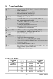
...) 2 x PCI Express x16 slot, running at x8 (Gen3/PCIE_2/PCIE_4) ASPEED® AST2300 supports 16MB VRAM Intel® C602 controller 2 x SATA 6Gb/s connectors (SATA0/SATA1) 4 x SATA 3Gb/s connectors (SATA2/SATA3/SATA4/SATA5) 4 x SAS connectors (4 additional SATA ports (3Gb/s) /option SAS ports (3Gb/s) with upgrade key required) Support for Intel RSTe SATA RAID 0, RAID 1 Up to 4 USB 2.0 ports (2 on the back panel, 2 additional ports via the USB brackets connected to the internal USB headers) 4 x USB 3.0 ports (4 on the back panel) Intel C600 Upgrade ROM SKUs: Upgrade ROM...
...) 2 x PCI Express x16 slot, running at x8 (Gen3/PCIE_2/PCIE_4) ASPEED® AST2300 supports 16MB VRAM Intel® C602 controller 2 x SATA 6Gb/s connectors (SATA0/SATA1) 4 x SATA 3Gb/s connectors (SATA2/SATA3/SATA4/SATA5) 4 x SAS connectors (4 additional SATA ports (3Gb/s) /option SAS ports (3Gb/s) with upgrade key required) Support for Intel RSTe SATA RAID 0, RAID 1 Up to 4 USB 2.0 ports (2 on the back panel, 2 additional ports via the USB brackets connected to the internal USB headers) 4 x USB 3.0 ports (4 on the back panel) Intel C600 Upgrade ROM SKUs: Upgrade ROM...
Manual
Page 12
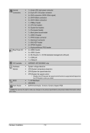
...12 - Internal Connectors Rear Panel I/O I/O Controller Hardware Monitor BIOS Form Factor ŠŠ 1 x 24-pin ATX main power connector ŠŠ 2 x 8-pin ATX 12V power connector ŠŠ 4 x SAS connectors (SATA 3Gb/s signal) ŠŠ 2 x SATA 6Gb/s connectors ŠŠ 4 x SATA 3Gb/s connectors ŠŠ 1 x PMBus header ŠŠ 2 x CPU fan headers ŠŠ 4 x System fan headers ŠŠ 1 x Front panel header ŠŠ 1 x Back plane borad header ŠŠ 1 x USB 2.0 header ŠŠ 1 x TPM module connector ŠŠ 1 x Serial port connector...
...12 - Internal Connectors Rear Panel I/O I/O Controller Hardware Monitor BIOS Form Factor ŠŠ 1 x 24-pin ATX main power connector ŠŠ 2 x 8-pin ATX 12V power connector ŠŠ 4 x SAS connectors (SATA 3Gb/s signal) ŠŠ 2 x SATA 6Gb/s connectors ŠŠ 4 x SATA 3Gb/s connectors ŠŠ 1 x PMBus header ŠŠ 2 x CPU fan headers ŠŠ 4 x System fan headers ŠŠ 1 x Front panel header ŠŠ 1 x Back plane borad header ŠŠ 1 x USB 2.0 header ŠŠ 1 x TPM module connector ŠŠ 1 x Serial port connector...
Manual
Page 15
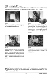
... the surface of the CPU cooler to the CPU fan header (CPU_FAN) on the motherboard. (Actual installation process may cause interference when you tighten the screws, remove it first and replace it after tightening the screws.) Step 3: Use one you just tightened. Step 4: Finally, attach the power connector of the installed CPU. Refer to the user's manual for your cooler has a fan grill which may differ...
... the surface of the CPU cooler to the CPU fan header (CPU_FAN) on the motherboard. (Actual installation process may cause interference when you tighten the screws, remove it first and replace it after tightening the screws.) Step 3: Use one you just tightened. Step 4: Finally, attach the power connector of the installed CPU. Refer to the user's manual for your cooler has a fan grill which may differ...
Manual
Page 16
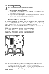
... be used . • Always turn off the computer and unplug the power cord from the power outlet before installing the memory to insert the memory, switch the direction. 1-4-1 Four Channel Memory Configuration This motherboard provides eight DDR3 memory sockets and supports Four Channel Technology. After the memory is recommended that memory of the same capacity, brand, speed, and chips be four times of the original memory bandwidth. A memory module can be installed in Four Channel mode...
... be used . • Always turn off the computer and unplug the power cord from the power outlet before installing the memory to insert the memory, switch the direction. 1-4-1 Four Channel Memory Configuration This motherboard provides eight DDR3 memory sockets and supports Four Channel Technology. After the memory is recommended that memory of the same capacity, brand, speed, and chips be four times of the original memory bandwidth. A memory module can be installed in Four Channel mode...
Manual
Page 18
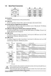
... cable connected to a back panel connector, first remove the cable from your device and then remove it from the connector. USB 2.0 Port The USB port supports the USB 2.0 specification. USB 3.0 Port The USB port supports the USB 3.0 specification. Use this port for USB devices such as a USB keyboard/mouse, USB printer, USB flash drive and etc. Hardware Installation - 18 - Do not rock it straight out from the motherboard. • When removing the cable, pull it side to side to 1 Gbps data rate. Speed LED Link Activity LED 10/100 LAN Port MLAN Speed LED...
... cable connected to a back panel connector, first remove the cable from your device and then remove it from the connector. USB 2.0 Port The USB port supports the USB 2.0 specification. USB 3.0 Port The USB port supports the USB 3.0 specification. Use this port for USB devices such as a USB keyboard/mouse, USB printer, USB flash drive and etc. Hardware Installation - 18 - Do not rock it straight out from the motherboard. • When removing the cable, pull it side to side to 1 Gbps data rate. Speed LED Link Activity LED 10/100 LAN Port MLAN Speed LED...
Manual
Page 22
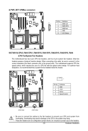
... motherboard supports CPU fan speed control, which requires the use of a CPU fan with fan speed control design. Overheating may result in the correct orientation (the black connector wire is recommended that a system fan be installed inside the chassis. 1 Pin No. 1 2 3 4 Definition GND +12V Sense Speed Control SYS_FAN1 SYS_FAN2 SYS_FAN3 SYS_FAN4 CPU0_FAN1 CPU1_FAN1 • Be sure to connect fan cables to the fan headers to the CPU or the system may hang. • These fan headers are not configuration jumper...
... motherboard supports CPU fan speed control, which requires the use of a CPU fan with fan speed control design. Overheating may result in the correct orientation (the black connector wire is recommended that a system fan be installed inside the chassis. 1 Pin No. 1 2 3 4 Definition GND +12V Sense Speed Control SYS_FAN1 SYS_FAN2 SYS_FAN3 SYS_FAN4 CPU0_FAN1 CPU1_FAN1 • Be sure to connect fan cables to the fan headers to the CPU or the system may hang. • These fan headers are not configuration jumper...

Manual
Page 32
1) BIOS_RVCR1 (BIOS Recovery Jumper) BIOS_RVCR1 1 1-2 Close: Normal operation. (Default setting) 1 2-3 Close: BIOS recovery mode. 8) PASSWORD1 (Clearing Supervisor Password Jumper) PASSWORD1 1 1-2 Close: Normal operation. (Default setting) 1 2-3 Close: Skip supervisor password. Hardware Installation - 32 -
1) BIOS_RVCR1 (BIOS Recovery Jumper) BIOS_RVCR1 1 1-2 Close: Normal operation. (Default setting) 1 2-3 Close: BIOS recovery mode. 8) PASSWORD1 (Clearing Supervisor Password Jumper) PASSWORD1 1 1-2 Close: Normal operation. (Default setting) 1 2-3 Close: Skip supervisor password. Hardware Installation - 32 -

Manual
Page 33
... the power cord from the jumper. Failure to do so may cause damage to the motherboard. • After system restart, go to BIOS Setup Exit menu and load factory defaults (select Restore Defaults) or manually configure the BIOS settings (refer to clear the CMOS values (e.g. 3) SSB_ME1 (ME enable/disable Jumper) SSB_ME1 1 1-2 Close: Normal operation. (Default setting) 1 2-3 Close: Disable ME function. 4) CLR_CMOS1 (Clearing CMOS Jumper) Use this jumper to Chapter 2, "BIOS Setup," for a few seconds. date information and BIOS configurations) and reset the CMOS...
... the power cord from the jumper. Failure to do so may cause damage to the motherboard. • After system restart, go to BIOS Setup Exit menu and load factory defaults (select Restore Defaults) or manually configure the BIOS settings (refer to clear the CMOS values (e.g. 3) SSB_ME1 (ME enable/disable Jumper) SSB_ME1 1 1-2 Close: Normal operation. (Default setting) 1 2-3 Close: Disable ME function. 4) CLR_CMOS1 (Clearing CMOS Jumper) Use this jumper to Chapter 2, "BIOS Setup," for a few seconds. date information and BIOS configurations) and reset the CMOS...

Manual
Page 36
.... (Default setting) 1 2-3 Close: Enable BIOS write protect function. 1 Hardware Installation - 36 - Please refer to reduce any risk of hard disk damage. 9/10) SATA_DOM_0/SATA_DOM_1 (SATA port 0 and port 1 DOM Jumpers) CAUTION! • If the SATA DOM power is supplied by the motherboard, set the jumper to pin 1-2. • If the SATA DOM power is supplied by external power, set the jumper to pin 2-3. • If a SATA type hard drive is connected to the motherboard, please ensure the jumper is closed and set to 2-3 pins (Default setting...
.... (Default setting) 1 2-3 Close: Enable BIOS write protect function. 1 Hardware Installation - 36 - Please refer to reduce any risk of hard disk damage. 9/10) SATA_DOM_0/SATA_DOM_1 (SATA port 0 and port 1 DOM Jumpers) CAUTION! • If the SATA DOM power is supplied by the motherboard, set the jumper to pin 1-2. • If the SATA DOM power is supplied by external power, set the jumper to pin 2-3. • If a SATA type hard drive is connected to the motherboard, please ensure the jumper is closed and set to 2-3 pins (Default setting...
Manual
Page 37
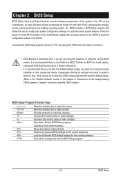
... reset the board to default values. (Refer to the "Restore Defaults" section in this chapter or introductions of the battery/clearing CMOS jumper in Chapter 1 for the current submenus Save all the changes and exit the BIOS Setup program - 37 - To access the BIOS Setup program, press the key during system startup, saving system parameters and loading operating system, etc. To flash the BIOS, do not encounter problems of using...
... reset the board to default values. (Refer to the "Restore Defaults" section in this chapter or introductions of the battery/clearing CMOS jumper in Chapter 1 for the current submenus Save all the changes and exit the BIOS Setup program - 37 - To access the BIOS Setup program, press the key during system startup, saving system parameters and loading operating system, etc. To flash the BIOS, do not encounter problems of using...
Manual
Page 43
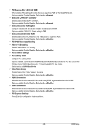
... Express Settings Press [Enter] for the related PCI-E slot. BIOS Setup PCI Express Slot 1/2/3/4 I /O ROM Enable/Disable onboard LAN devices and initialize device expansion ROM. Onboard LAN1/2/3/4 Controller Enable/Disable Onboard LAN controllers. Onboard LAN I/O ROM Option Configure onboard LAN devices and initialize device expansion ROM. Options available: 32 PCI Bus Clocks/64 PCI Bus Clocks/96 PCI Bus Clocks/128 PCI Bus Clocks/160 PCI Bus Clocks/192 PCI Bus Clocks/224 PCI Bus Clocks/248 PCI Bus Clocks. Options available: Enabled/Disabled. Options available: Enabled/Disabled. Default...
... Express Settings Press [Enter] for the related PCI-E slot. BIOS Setup PCI Express Slot 1/2/3/4 I /O ROM Enable/Disable onboard LAN devices and initialize device expansion ROM. Onboard LAN1/2/3/4 Controller Enable/Disable Onboard LAN controllers. Onboard LAN I/O ROM Option Configure onboard LAN devices and initialize device expansion ROM. Options available: 32 PCI Bus Clocks/64 PCI Bus Clocks/96 PCI Bus Clocks/128 PCI Bus Clocks/160 PCI Bus Clocks/192 PCI Bus Clocks/224 PCI Bus Clocks/248 PCI Bus Clocks. Options available: Enabled/Disabled. Options available: Enabled/Disabled. Default...
Manual
Page 44
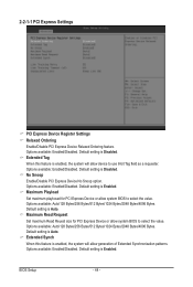
... Wnen this feature is enabled, the system will allow generation of Extended Synchronization patterns. Default setting is Enabled. Default setting is Disabled. Maximum Read Request Set maximum Read Reuest size for PCI Express Device or allow system BIOS to use 8-bit Tag field as a requester. Default setting is Auto. Options available: Auto/128 Bytes/256 Bytes/512 Bytes/1024 Bytes/2048 Bytes/4096 Bytes. 2-2-1-1 PCI Express Settings PCI Express Device Register Settings Relaxed Ordering Enable/DIsable PCI Express Device Relaxed Ordering feature.
... Wnen this feature is enabled, the system will allow generation of Extended Synchronization patterns. Default setting is Enabled. Default setting is Disabled. Maximum Read Request Set maximum Read Reuest size for PCI Express Device or allow system BIOS to use 8-bit Tag field as a requester. Default setting is Auto. Options available: Auto/128 Bytes/256 Bytes/512 Bytes/1024 Bytes/2048 Bytes/4096 Bytes. 2-2-1-1 PCI Express Settings PCI Express Device Register Settings Relaxed Ordering Enable/DIsable PCI Express Device Relaxed Ordering feature.
Manual
Page 48
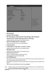
... input value of the processor when queried. CPU Speed / 64-bit Displays the technical specifications for the installed processor. Options available: All/1/2/3. Active Processor Cores (Note) Allows you install a CPU that supports this feature. Default setting is Disabled. (Note) This item is All. Intel HT Technology / Intel VT-x Technology Displays the support information for the installed processor. When disabled, the processor will limit the maximum COUID input values to enable all CPU cores. Options available: Enabled/Disabled. Cache Information L1 Data...
... input value of the processor when queried. CPU Speed / 64-bit Displays the technical specifications for the installed processor. Options available: All/1/2/3. Active Processor Cores (Note) Allows you install a CPU that supports this feature. Default setting is Disabled. (Note) This item is All. Intel HT Technology / Intel VT-x Technology Displays the support information for the installed processor. When disabled, the processor will limit the maximum COUID input values to enable all CPU cores. Options available: Enabled/Disabled. Cache Information L1 Data...
Manual
Page 53
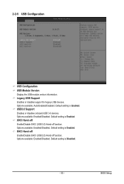
...Options available: Enabled/Disabled. Default setting is Disabled. - 53 - Default setting is Enabled. Default setting is Enabled. Default setting is Enabled. EHCI Hand-off Enable/Disable EHCI (USB 2.0) Hand-off function. Options available: Enabled/Disabled. USB3.0 Support Enables or disables onboard USB 3.0 devices. Legacy USB Support Enables or disables support for legacy USB devices. Options available: Enabled/Disabled. BIOS Setup XHCI Hand-off Enable/Disable EHCI (USB 3.0) Hand-off function. 2-2-5 USB Configuration USB Configuration USB Module Version Display...
...Options available: Enabled/Disabled. Default setting is Disabled. - 53 - Default setting is Enabled. Default setting is Enabled. Default setting is Enabled. EHCI Hand-off Enable/Disable EHCI (USB 2.0) Hand-off function. Options available: Enabled/Disabled. USB3.0 Support Enables or disables onboard USB 3.0 devices. Legacy USB Support Enables or disables support for legacy USB devices. Options available: Enabled/Disabled. BIOS Setup XHCI Hand-off Enable/Disable EHCI (USB 3.0) Hand-off function. 2-2-5 USB Configuration USB Configuration USB Module Version Display...

Manual
Page 62
... Enable/Boot Loader. Out-of-Bnad Mgmt Port Microsoft Windows Emerency Management Service (EMS) allows for COM1. When disabled, COM1 Switch to AST2300 SOL UART. Options available: Enabled/Disabled. BIOS Setup - 62 - Options available: 1/2. Once the buffers are full, a 'stop bit. Recorder Mode (Note) When this mode enabled, only text will be sent to enable console redirection after O.S has loaded. Options available: Enabled/Disabled. SOL Switch When enabled, COM1 Switch to IT8728 SOL UART. Default setting is Disabled...
... Enable/Boot Loader. Out-of-Bnad Mgmt Port Microsoft Windows Emerency Management Service (EMS) allows for COM1. When disabled, COM1 Switch to AST2300 SOL UART. Options available: Enabled/Disabled. BIOS Setup - 62 - Options available: 1/2. Once the buffers are full, a 'stop bit. Recorder Mode (Note) When this mode enabled, only text will be sent to enable console redirection after O.S has loaded. Options available: Enabled/Disabled. SOL Switch When enabled, COM1 Switch to IT8728 SOL UART. Default setting is Disabled...

Manual
Page 68
... of advanced items. Compatibility RID Enable/Disable Compatibility RID function. Mirroring/Sparing Displays the current support memory mode. Default setting is Enabled. The Rank Interleaving works between different physical banks. Default setting is Enabled. IOH Configuration Press [Enter] for configuration of advanced items. QPI Configuration Press [Enter] for configuration of the installed memory. Memory Mode Determine the memory mode. Options available: Indpendent /Mirroring/ Lockstep/Sparing. When set to Lockstep mode, the motherboard uses two areas of...
... of advanced items. Compatibility RID Enable/Disable Compatibility RID function. Mirroring/Sparing Displays the current support memory mode. Default setting is Enabled. The Rank Interleaving works between different physical banks. Default setting is Enabled. IOH Configuration Press [Enter] for configuration of advanced items. QPI Configuration Press [Enter] for configuration of the installed memory. Memory Mode Determine the memory mode. Options available: Indpendent /Mirroring/ Lockstep/Sparing. When set to Lockstep mode, the motherboard uses two areas of...

Manual
Page 69
Options available: Enabled/Disabled. Options available: Enabled/Disabled. Options available: Auto/300 M/900 M/1500 M/3000 M. When disabled, the system will enforce 1600MHz LRDIMM. DIMM Information Press [Enter] for configuration to increase or decrease the desired values. Options available: Enabled/Disabled. Rank Margin Enable/Disable Rank Margin function. Options available: Disabled/OLTT/CLTT. Default setting is Enforce DIS. Options available: Enabled/Disabled. OLTT Peak BW % Press the numberic keys to view installed DIMM information. - 69 - ...
Options available: Enabled/Disabled. Options available: Enabled/Disabled. Options available: Auto/300 M/900 M/1500 M/3000 M. When disabled, the system will enforce 1600MHz LRDIMM. DIMM Information Press [Enter] for configuration to increase or decrease the desired values. Options available: Enabled/Disabled. Rank Margin Enable/Disable Rank Margin function. Options available: Disabled/OLTT/CLTT. Default setting is Enforce DIS. Options available: Enabled/Disabled. OLTT Peak BW % Press the numberic keys to view installed DIMM information. - 69 - ...

Manual
Page 71
... Default setting is Disabled. Options available: Auto/Manual. Intel(R) VT-d Enable/Disable Intel VT-d Technology function. Default setting is VC1. IOH Resource Seletion Type Configure IOH Resource Seletion Type. Default setting is Offboard. Default setting is Enabled. - 71 - TargetVGA Display the Target VGA support informaiton. Options available: Enabled/Disabled. Default setting is Disabled. Options available: Enabled/Disabled. MMCFGBASE (Base address of the Memory Mapped Configuration Space) Options available: 1G/2G/4G/8G/16G/32G/64G. BIOS Setup Default...
... Default setting is Disabled. Options available: Auto/Manual. Intel(R) VT-d Enable/Disable Intel VT-d Technology function. Default setting is VC1. IOH Resource Seletion Type Configure IOH Resource Seletion Type. Default setting is Offboard. Default setting is Enabled. - 71 - TargetVGA Display the Target VGA support informaiton. Options available: Enabled/Disabled. Default setting is Disabled. Options available: Enabled/Disabled. MMCFGBASE (Base address of the Memory Mapped Configuration Space) Options available: 1G/2G/4G/8G/16G/32G/64G. BIOS Setup Default...
Manual
Page 72
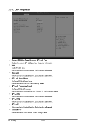
... Enabled. BIOS Setup - 72 - Options available: Auto/6.4 GT/s7.2 GT/s/8.6 GT/s. QPI Link1 Options available: Enabled/Disabled. Default setting is Disabled. Options available: Enabled/Disabled. Isoc Enable/Disable Isoc. Default setting is Disabled. Default setting is Auto. MesegEN Options available: Enabled/Disabled. QPI Link0s Options available: Enabled/Disabled. Default setting is Disabled. QPI Link Speed Mode Configure QPI Link Speed mode. Default setting is Fast. Default setting is Disabled. QPI Link0p Options available: Enabled/Disabled. QPI Link Frequency...
... Enabled. BIOS Setup - 72 - Options available: Auto/6.4 GT/s7.2 GT/s/8.6 GT/s. QPI Link1 Options available: Enabled/Disabled. Default setting is Disabled. Options available: Enabled/Disabled. Isoc Enable/Disable Isoc. Default setting is Disabled. Default setting is Auto. MesegEN Options available: Enabled/Disabled. QPI Link0s Options available: Enabled/Disabled. Default setting is Disabled. QPI Link Speed Mode Configure QPI Link Speed mode. Default setting is Fast. Default setting is Disabled. QPI Link0p Options available: Enabled/Disabled. QPI Link Frequency...


