User Manual
Page 11
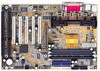
... mode Ÿ 2 Serial Ports (COMA & COMB) Ÿ 4 USB ports Ÿ 1 IrDA connector for Fast IrDA Ÿ CPU/Power Supply/Chassis Fan Revolution detect Ÿ CPU Fan Control Ÿ System Voltage Detect Ÿ CPU Overheat Warning Ÿ Chassis Intrusion Detect Ÿ Display Actual Current Voltage To be continued... 3 7IX Motherboard Summary Of Features Form factor CPU Chipset Clock Generator Memory I/O Control Slots On-Board IDE On-Board Peripherals Hardware Monitor (Optional) Ÿ 30.5 cm x 20.7 cm ATX SIZE form factor, 4 layers PCB. Ÿ AMD Athlon(K7) Slot A Processor...
... mode Ÿ 2 Serial Ports (COMA & COMB) Ÿ 4 USB ports Ÿ 1 IrDA connector for Fast IrDA Ÿ CPU/Power Supply/Chassis Fan Revolution detect Ÿ CPU Fan Control Ÿ System Voltage Detect Ÿ CPU Overheat Warning Ÿ Chassis Intrusion Detect Ÿ Display Actual Current Voltage To be continued... 3 7IX Motherboard Summary Of Features Form factor CPU Chipset Clock Generator Memory I/O Control Slots On-Board IDE On-Board Peripherals Hardware Monitor (Optional) Ÿ 30.5 cm x 20.7 cm ATX SIZE form factor, 4 layers PCB. Ÿ AMD Athlon(K7) Slot A Processor...
User Manual
Page 15
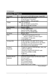
7IX Motherboard $ Page index for Connectors / Panel and Jumper Definition Page Connectors P.7 COMA / COMB / LPT Port P.7 USB Connector P.7 PS/2 Keyboard & PS/2 Mouse Connector P.8 PWR FAN P.8 CPU FAN / SYSTEM FAN P.9 ATX PWR P.10 FLOPPY P.10 IDE 1(Primary) / IDE 2(Secondary) P.11 USB Port P.11 IR (Optional) P.12 Panel and Jumper Definition P.13 J22 (2x11 pins jumper) P.13 JP10 (Keyboard Power On) P.14 JP1 (CASE OPEN) P.14 JP3 (CLEAR CMOS) P.15 JP9 (RING PWR ON) P.15 JP4 (Wake On LAN) P.16 JP5 (Internal Buzzer Connector)[Optional] P.16 BAT 1 P.17 7
7IX Motherboard $ Page index for Connectors / Panel and Jumper Definition Page Connectors P.7 COMA / COMB / LPT Port P.7 USB Connector P.7 PS/2 Keyboard & PS/2 Mouse Connector P.8 PWR FAN P.8 CPU FAN / SYSTEM FAN P.9 ATX PWR P.10 FLOPPY P.10 IDE 1(Primary) / IDE 2(Secondary) P.11 USB Port P.11 IR (Optional) P.12 Panel and Jumper Definition P.13 J22 (2x11 pins jumper) P.13 JP10 (Keyboard Power On) P.14 JP1 (CASE OPEN) P.14 JP3 (CLEAR CMOS) P.15 JP9 (RING PWR ON) P.15 JP4 (Wake On LAN) P.16 JP5 (Internal Buzzer Connector)[Optional] P.16 BAT 1 P.17 7
User Manual
Page 21
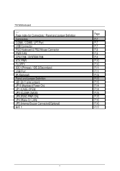
7IX Motherboard IDE1(Primary) , IDE2 (Secondary) USB : USB Port RED LINE IDE 1 IDE 2 Pin No. Definition 1 VCC 2 USB D0− 3 USB D0+ 1 4 GND 5 VCC 6 USB D1− 7 USB D1+ 8 GND 11
7IX Motherboard IDE1(Primary) , IDE2 (Secondary) USB : USB Port RED LINE IDE 1 IDE 2 Pin No. Definition 1 VCC 2 USB D0− 3 USB D0+ 1 4 GND 5 VCC 6 USB D1− 7 USB D1+ 8 GND 11
User Manual
Page 23
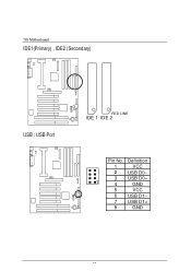
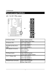
7IX Motherboard Panel and Jumper Definition J22 : For 2X11 PINs Jumper 1 1 P−P−P+ HD J22 1 1 PW RE GD GN (Green Switch) GD (Green LED) HD (IDE Hard Disk Active LED) SPK (Speaker Connector) RE (Reset Switch) P+P−P−(Power LED) PW (Soft Power Connector) Open: Normal Operation Close: Entering Green Mode Pin 1: LED anode(+) Pin 2: LED cathode(−) Pin 1: LED anode(+) Pin 2: LED cathode(−) Pin 1: VCC(+) Pin 2- Pin 3: NC Pin 4: Data(−) Open: Normal Operation Close: Reset Hardware System Pin 1: LED anode(+) Pin 2: LED cathode(−) Pin 3: LED ...
7IX Motherboard Panel and Jumper Definition J22 : For 2X11 PINs Jumper 1 1 P−P−P+ HD J22 1 1 PW RE GD GN (Green Switch) GD (Green LED) HD (IDE Hard Disk Active LED) SPK (Speaker Connector) RE (Reset Switch) P+P−P−(Power LED) PW (Soft Power Connector) Open: Normal Operation Close: Entering Green Mode Pin 1: LED anode(+) Pin 2: LED cathode(−) Pin 1: LED anode(+) Pin 2: LED cathode(−) Pin 1: VCC(+) Pin 2- Pin 3: NC Pin 4: Data(−) Open: Normal Operation Close: Reset Hardware System Pin 1: LED anode(+) Pin 2: LED cathode(−) Pin 3: LED ...
User Manual
Page 30
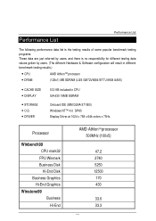
... different testing data values gotten by users. (The different Hardware & Software configuration will result in different benchmark testing results.) • CPU AMD AthlonTM processor • DRAM (128x1) MB SDRAM (LGS GM72V66841ET7J 9908 AA05) • CACHE SIZE • DISPLAY • STORAGE • O.S. • DRIVER 512 KB included in CPU GA-630 16MB SGRAM Onboard IDE (IBM DJNA-371800) Windows NT™ 4.0 SPK5 Display Driver at 1024 x 768 x 64k colors...
... different testing data values gotten by users. (The different Hardware & Software configuration will result in different benchmark testing results.) • CPU AMD AthlonTM processor • DRAM (128x1) MB SDRAM (LGS GM72V66841ET7J 9908 AA05) • CACHE SIZE • DISPLAY • STORAGE • O.S. • DRIVER 512 KB included in CPU GA-630 16MB SGRAM Onboard IDE (IBM DJNA-371800) Windows NT™ 4.0 SPK5 Display Driver at 1024 x 768 x 64k colors...
User Manual
Page 32
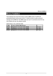
... Supports 8 / 16 / 32 / 64 / 128 / 256 MB Supports 8 / 16 / 32 / 64 / 128 / 256 MB X 1 pcs X 1 pcs X 1 pcs 20 Install memory in one direction due to the two notch. Memory Installation Memory Installation The motherboard has 3 dual inline memory module (DIMM) sockets. To install the memory module, just push it vertically into the DIMM Slot .The DIMM module can vary between sockets. The BIOS will automatically detects memory type and size...
... Supports 8 / 16 / 32 / 64 / 128 / 256 MB Supports 8 / 16 / 32 / 64 / 128 / 256 MB X 1 pcs X 1 pcs X 1 pcs 20 Install memory in one direction due to the two notch. Memory Installation Memory Installation The motherboard has 3 dual inline memory module (DIMM) sockets. To install the memory module, just push it vertically into the DIMM Slot .The DIMM module can vary between sockets. The BIOS will automatically detects memory type and size...
User Manual
Page 35
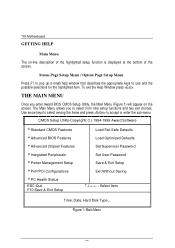
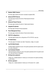
... Help Window press . CMOS Setup Utility-Copyright( C ) 1984-1999 Award Software 4Standard CMOS Features 4Advanced BIOS Features 4Advanced Chipset Features 4Integrated Peripherals 4Power Management Setup 4PnP/PCI Configurations 4PC Health Status ESC:Quit F10:Save & Exit Setup Load Fail-Safe Defaults Load Optimized Defaults Set Supervisor Password Set User Password Save & Exit Setup Exit Without Saving Select Item Time, Date, Hard Disk Type... Status Page Setup Menu / Option Page Setup Menu Press F1 to pop up a small help window that describes the appropriate keys...
... Help Window press . CMOS Setup Utility-Copyright( C ) 1984-1999 Award Software 4Standard CMOS Features 4Advanced BIOS Features 4Advanced Chipset Features 4Integrated Peripherals 4Power Management Setup 4PnP/PCI Configurations 4PC Health Status ESC:Quit F10:Save & Exit Setup Load Fail-Safe Defaults Load Optimized Defaults Set Supervisor Password Set User Password Save & Exit Setup Exit Without Saving Select Item Time, Date, Hard Disk Type... Status Page Setup Menu / Option Page Setup Menu Press F1 to pop up a small help window that describes the appropriate keys...
User Manual
Page 36
... setup page is the System auto detect Temperature, voltage , fan, speed. • Load Fail-Safe Defaults Fail-Safe Defaults indicates the value of the system parameters which the system would be in safe configuration. • Load Optimized Defaults Optimized Defaults indicates the value of the system parameters which the system would be in best performance configuration. • Set Supervisor password Change, set , or disable password. It allows you to limit access to Setup. • Set User password Change, set , or disable password...
... setup page is the System auto detect Temperature, voltage , fan, speed. • Load Fail-Safe Defaults Fail-Safe Defaults indicates the value of the system parameters which the system would be in safe configuration. • Load Optimized Defaults Optimized Defaults indicates the value of the system parameters which the system would be in best performance configuration. • Set Supervisor password Change, set , or disable password. It allows you to limit access to Setup. • Set User password Change, set , or disable password...
User Manual
Page 39
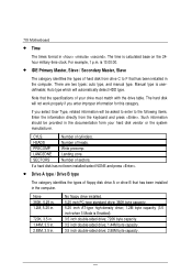
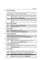
... AT-type high-density drive; 1.2M byte capacity (3.5 inch when 3 Mode is 13:00:00. • IDE Primary Master, Slave / Secondary Master, Slave The category identifies the types of hard disk from the keyboard and press . Auto type which will be provided in the computer. Number of your hard disk vendor or the system manufacturer. 7IX Motherboard • Time The times format in . is Enabled). 3.5 inch...
... AT-type high-density drive; 1.2M byte capacity (3.5 inch when 3 Mode is 13:00:00. • IDE Primary Master, Slave / Secondary Master, Slave The category identifies the types of hard disk from the keyboard and press . Auto type which will be provided in the computer. Number of your hard disk vendor or the system manufacturer. 7IX Motherboard • Time The times format in . is Enabled). 3.5 inch...
User Manual
Page 42
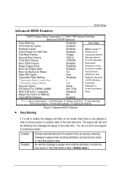
... problem. Capability Report No FDD For WIN 95 Video BIOS Shadow Disabled Enabled Enabled Enabled Floppy HDD-0 CDROM Enabled Disabled Enabled On Fast Disabled 6 250 Setup Non-OS2 Disabled No Enabled Item Help Menu Level 4 Allows you to the boot sector or partition table of the hard disk drive. You can run anti-virus program to access the boot sector or hard disk partition table. ( Default value ) 30 BIOS Setup Advanced BIOS Features CMOS Setup Utility-Copyright( C ) 1984-1999 Award Software Advanced BIOS Features Virus Warning CPU Internal...
... problem. Capability Report No FDD For WIN 95 Video BIOS Shadow Disabled Enabled Enabled Enabled Floppy HDD-0 CDROM Enabled Disabled Enabled On Fast Disabled 6 250 Setup Non-OS2 Disabled No Enabled Item Help Menu Level 4 Allows you to the boot sector or partition table of the hard disk drive. You can run anti-virus program to access the boot sector or hard disk partition table. ( Default value ) 30 BIOS Setup Advanced BIOS Features CMOS Setup Utility-Copyright( C ) 1984-1999 Award Software Advanced BIOS Features Virus Warning CPU Internal...
User Manual
Page 44
... Rate Setting Enabled Disabled Enable Keyboard Typematic rate setting. Per second. ( Default value : 6 ) • Typematic Delay (Msec.) ( 250 ) 250-1000 Set the time delay from 6 chars. The system will boot, but access to Setup. Set Gate A20 Option is not entered at the prompt. Per second to determine it is 40 tracks 720 K, 1.2 M and 1.44 M are all 80 tracks. Enabled Disabled BIOS searches for the type of floppy disk drive by...
... Rate Setting Enabled Disabled Enable Keyboard Typematic rate setting. Per second. ( Default value : 6 ) • Typematic Delay (Msec.) ( 250 ) 250-1000 Set the time delay from 6 chars. The system will boot, but access to Setup. Set Gate A20 Option is not entered at the prompt. Per second to determine it is 40 tracks 720 K, 1.2 M and 1.44 M are all 80 tracks. Enabled Disabled BIOS searches for the type of floppy disk drive by...
User Manual
Page 46
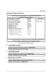
... Value Enabled Enabled Disabled 64 Optimal Disabled 32 Cycle 8 Cycle Auto 8 Cycle 3 Cycle 5 Cycle 3 Cycle 3 Cycle Item Help Menu Level 4 Move Enter:Select +/-/PU/PD:Value F10:Save ESC:Exit F1:General Help F5:Previous Values F6:Fail-Safe Defaults F7:Optimized Defaults Figure 4: Advanced Chipset Features • System BIOS Cacheable Enabled Enable System BIOS Cacheable. ( Default value ) Disabled Disable System BIOS Cacheable. • Video RAM Cacheable Enabled Enable video RAM Cacheable. ( Default value ) Disabled Disable video RAM Cacheable. • Memory...
... Value Enabled Enabled Disabled 64 Optimal Disabled 32 Cycle 8 Cycle Auto 8 Cycle 3 Cycle 5 Cycle 3 Cycle 3 Cycle Item Help Menu Level 4 Move Enter:Select +/-/PU/PD:Value F10:Save ESC:Exit F1:General Help F5:Previous Values F6:Fail-Safe Defaults F7:Optimized Defaults Figure 4: Advanced Chipset Features • System BIOS Cacheable Enabled Enable System BIOS Cacheable. ( Default value ) Disabled Disable System BIOS Cacheable. • Video RAM Cacheable Enabled Enable video RAM Cacheable. ( Default value ) Disabled Disable video RAM Cacheable. • Memory...
User Manual
Page 50
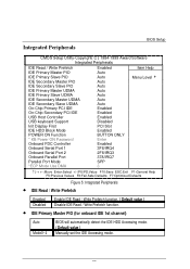
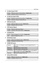
... UDMA On-Chip Primary PCI IDE On-Chip Secondary PCI IDE USB Host Controller USB keyboard Support Init Display First IDE HDD Block Mode POWER ON Function * KB Power ON Password Onboard FDC Controller Onboard Serial Port 1 Onboard Serial Port 2 Onboard Parallel Port Parallel Port Mode *ECP Mode Use DMA Enabled Auto Auto Auto Auto Auto Auto Auto Auto Enabled Enabled Enabled Disabled PCI Slot Enabled BUTTON ONLY Enter Enabled 3F8/IRQ4 2F8/IRQ3 378/IRQ7 SPP 3 Item Help Menu Level 4 Move Enter:Select +/-/PU/PD:Value F10:Save ESC:Exit F1:General Help F5:Previous Values F6:Fail-Safe Defaults F7...
... UDMA On-Chip Primary PCI IDE On-Chip Secondary PCI IDE USB Host Controller USB keyboard Support Init Display First IDE HDD Block Mode POWER ON Function * KB Power ON Password Onboard FDC Controller Onboard Serial Port 1 Onboard Serial Port 2 Onboard Parallel Port Parallel Port Mode *ECP Mode Use DMA Enabled Auto Auto Auto Auto Auto Auto Auto Auto Enabled Enabled Enabled Disabled PCI Slot Enabled BUTTON ONLY Enter Enabled 3F8/IRQ4 2F8/IRQ3 378/IRQ7 SPP 3 Item Help Menu Level 4 Move Enter:Select +/-/PU/PD:Value F10:Save ESC:Exit F1:General Help F5:Previous Values F6:Fail-Safe Defaults F7...
User Manual
Page 52
.... Disable USB Keyboard Support. ( Default value ) • Init Display First PCI Slot AGP Set Init Display First to PCI Slot. ( Default value ) Set Init Display First to AGP. • IDE HDD Block Mode Enabled Disabled Enable IDE HDD Block Mode. ( Default value ) Disable IDE HDD Block Mode. • POWER ON Function Password Mouse Left Mouse Right BUTTON ONLY Power Key Enter from 1 to 5 characters to power on PS/2 left bottom. BIOS Setup • On-Chip Primary PCI IDE Enabled Disabled Enable onboard 1st channel IDE port. ( Default value ) Disable onboard 1st channel IDE port...
.... Disable USB Keyboard Support. ( Default value ) • Init Display First PCI Slot AGP Set Init Display First to PCI Slot. ( Default value ) Set Init Display First to AGP. • IDE HDD Block Mode Enabled Disabled Enable IDE HDD Block Mode. ( Default value ) Disable IDE HDD Block Mode. • POWER ON Function Password Mouse Left Mouse Right BUTTON ONLY Power Key Enter from 1 to 5 characters to power on PS/2 left bottom. BIOS Setup • On-Chip Primary PCI IDE Enabled Disabled Enable onboard 1st channel IDE port. ( Default value ) Disable onboard 1st channel IDE port...
User Manual
Page 54
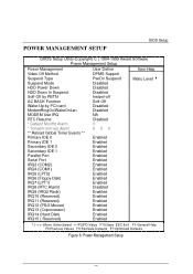
POWER MANAGEMENT SETUP BIOS Setup CMOS Setup Utility-Copyright( C ) 1984-1999 Award Software Power Management Setup Power Management Video Off Method Suspend Type Suspend Mode HDD Power Down HDD Down In Suspend Soft-Off by PBTN AC BACK Function Wake-Up by PCI card ModemRingOn/WakeOnLan MODEM Use IRQ RTC Resume * Date(of Month) Alarm * Time(hh:mm:ss) Alarm ** Reload Global Timer Events ** Primary IDE 0 Primary IDE 1 Secondary IDE 0 Secondary IDE 1 Parallel Port Serial Port IRQ3 (COM2) IRQ4 (COM1...
POWER MANAGEMENT SETUP BIOS Setup CMOS Setup Utility-Copyright( C ) 1984-1999 Award Software Power Management Setup Power Management Video Off Method Suspend Type Suspend Mode HDD Power Down HDD Down In Suspend Soft-Off by PBTN AC BACK Function Wake-Up by PCI card ModemRingOn/WakeOnLan MODEM Use IRQ RTC Resume * Date(of Month) Alarm * Time(hh:mm:ss) Alarm ** Reload Global Timer Events ** Primary IDE 0 Primary IDE 1 Secondary IDE 0 Secondary IDE 1 Parallel Port Serial Port IRQ3 (COM2) IRQ4 (COM1...
User Manual
Page 58
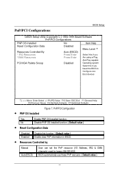
PnP/PCI Configurations BIOS Setup CMOS Setup Utility-Copyright( C ) 1984-1999 Award Software PnP/PCI Configurations PNP OS Installed Reset Configuration Data Resources Controlled By * IRQ Resources *DMA Resources No Disabled Auto (ESCD) Press Enter Press Enter Item Help Menu Level 4 Select Yes if you Are using a Plug And Play capable PCI/VGA Palette Snoop Disabled Operating system Select No if you Need the BIOS to Configure non- Boot devices Move Enter:Select +/-/PU/PD:Value F10:Save ESC:Exit F1...
PnP/PCI Configurations BIOS Setup CMOS Setup Utility-Copyright( C ) 1984-1999 Award Software PnP/PCI Configurations PNP OS Installed Reset Configuration Data Resources Controlled By * IRQ Resources *DMA Resources No Disabled Auto (ESCD) Press Enter Press Enter Item Help Menu Level 4 Select Yes if you Are using a Plug And Play capable PCI/VGA Palette Snoop Disabled Operating system Select No if you Need the BIOS to Configure non- Boot devices Move Enter:Select +/-/PU/PD:Value F10:Save ESC:Exit F1...
User Manual
Page 60
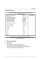
.... 48 PC Health Status BIOS Setup CMOS Setup Utility-Copyright( C ) 1984-1999 Award Software PC Health Status Reset Case Open Status Case Opened Shutdown Temperature CPU Warning Temperature CPU FAN Fail Alarm System FAN Fail Alarm Power FAN Fail Alarm Current System Temp. Current CPU Temperature CPU FAN Speed System FAN Speed Power FAN Speed VCORE VSRAM VCC3 + 5V +12V - 12V - 5V VBAT 5VSB Disabled No 75°C/167°F 70°C/158°F Disabled Disabled Disabled 40°C/104°F 39...
.... 48 PC Health Status BIOS Setup CMOS Setup Utility-Copyright( C ) 1984-1999 Award Software PC Health Status Reset Case Open Status Case Opened Shutdown Temperature CPU Warning Temperature CPU FAN Fail Alarm System FAN Fail Alarm Power FAN Fail Alarm Current System Temp. Current CPU Temperature CPU FAN Speed System FAN Speed Power FAN Speed VCORE VSRAM VCC3 + 5V +12V - 12V - 5V VBAT 5VSB Disabled No 75°C/167°F 70°C/158°F Disabled Disabled Disabled 40°C/104°F 39...
User Manual
Page 65
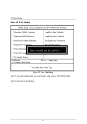
...Setup Utility and save the user setup value to Setup Utility. 53 Figure 12: Save & Exit Setup Type "Y" will return to RTC CMOS SRAM. N 4PnP/PCI Configurations Exit Without Saving 4PC Health Status ESC:Quit F10:Save & Exit Setup Select Item Time, Date, Hard Disk Type... 7IX Motherboard Save & Exit Setup CMOS Setup Utility-Copyright( C ) 1984-1999 Award Software 4Standard CMOS Features Load Fail-Safe Defaults 4Advanced BIOS Features Load Optimized Defaults 4Advanced Chipset Features Set Supervisor Password 4Integrated Peripherals Set User Password 4Power Management Setup...
...Setup Utility and save the user setup value to Setup Utility. 53 Figure 12: Save & Exit Setup Type "Y" will return to RTC CMOS SRAM. N 4PnP/PCI Configurations Exit Without Saving 4PC Health Status ESC:Quit F10:Save & Exit Setup Select Item Time, Date, Hard Disk Type... 7IX Motherboard Save & Exit Setup CMOS Setup Utility-Copyright( C ) 1984-1999 Award Software 4Standard CMOS Features Load Fail-Safe Defaults 4Advanced BIOS Features Load Optimized Defaults 4Advanced Chipset Features Set Supervisor Password 4Integrated Peripherals Set User Password 4Power Management Setup...
User Manual
Page 66
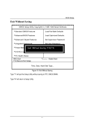
... to Setup Utility. 54 Figure 13: Exit Without Saving Type "Y" will return to RTC CMOS SRAM. Exit Without Saving BIOS Setup CMOS Setup Utility-Copyright( C ) 1984-1999 Award Software 4Standard CMOS Features Load Fail-Safe Defaults 4Advanced BIOS Features Load Optimized Defaults 4Advanced Chipset Features Set Supervisor Password 4Integrated Peripherals Set User Password 4Power ManagemQeunittSWetuitphout SavingSa(Yve/N&)?ExNit Setup 4PnP/PCI Configurations Exit Without Saving 4PC Health Status ESC:Quit F10:Save & Exit Setup Select Item Time, Date, Hard Disk Type...
... to Setup Utility. 54 Figure 13: Exit Without Saving Type "Y" will return to RTC CMOS SRAM. Exit Without Saving BIOS Setup CMOS Setup Utility-Copyright( C ) 1984-1999 Award Software 4Standard CMOS Features Load Fail-Safe Defaults 4Advanced BIOS Features Load Optimized Defaults 4Advanced Chipset Features Set Supervisor Password 4Integrated Peripherals Set User Password 4Power ManagemQeunittSWetuitphout SavingSa(Yve/N&)?ExNit Setup 4PnP/PCI Configurations Exit Without Saving 4PC Health Status ESC:Quit F10:Save & Exit Setup Select Item Time, Date, Hard Disk Type...
User Manual
Page 67
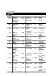
... Input Output Advanced Programmable Input Controller Dual inline memory module Dynamic random access memory To be Meaning Acro. Meaning ACPI Advanced configuration and power interface POST Power-on self test LAN Local area network ECP Extended capabilities port APM Advanced power management DMA Direct memory access MHz Megahertz ESCD CPU SMP USB OS Extended system configuration data Central processing unit Symmetric multiprocessing Universal serial bus Operating System Acro. 7IX Motherboard Appendix Acronyms Acro.
... Input Output Advanced Programmable Input Controller Dual inline memory module Dynamic random access memory To be Meaning Acro. Meaning ACPI Advanced configuration and power interface POST Power-on self test LAN Local area network ECP Extended capabilities port APM Advanced power management DMA Direct memory access MHz Megahertz ESCD CPU SMP USB OS Extended system configuration data Central processing unit Symmetric multiprocessing Universal serial bus Operating System Acro. 7IX Motherboard Appendix Acronyms Acro.


