Manual
Page 1
GA-790XTA-UD4 AM3 socket motherboard for AMD Phenom™ II processor/AMD Athlon™ II processor User's Manual Rev. 1001 12ME-790XTA4-1001R
GA-790XTA-UD4 AM3 socket motherboard for AMD Phenom™ II processor/AMD Athlon™ II processor User's Manual Rev. 1001 12ME-790XTA4-1001R
Manual
Page 2
Motherboard GA-790XTA-UD4 Nov. 20, 2009 Motherboard GA-790XTA-UD4 Nov. 20, 2009
Motherboard GA-790XTA-UD4 Nov. 20, 2009 Motherboard GA-790XTA-UD4 Nov. 20, 2009
Manual
Page 3
...product. Documentation Classifications In order to the specifications and features in the use GIGABYTE's unique features, read or download the information on/from the Support&Downloads\Motherboard\Technology Guide page on our website. For product-related information, check on our... website at: http://www.gigabyte.com.tw Identifying Your Motherboard Revision The revision number on how to their respective owners. For instructions on your motherboard revision before updating motherboard BIOS, drivers, or when looking for technical information. ...
...product. Documentation Classifications In order to the specifications and features in the use GIGABYTE's unique features, read or download the information on/from the Support&Downloads\Motherboard\Technology Guide page on our website. For product-related information, check on our... website at: http://www.gigabyte.com.tw Identifying Your Motherboard Revision The revision number on how to their respective owners. For instructions on your motherboard revision before updating motherboard BIOS, drivers, or when looking for technical information. ...
Manual
Page 4
Table of Contents Box Contents...6 Optional Items...6 GA-790XTA-UD4 Motherboard Layout 7 Block Diagram...8 Chapter 1 Hardware Installation 9 1-1 Installation Precautions 9 1-2 Product Specifications 10 1-3 Installing the CPU and CPU Cooler 13 1-3-1 Installing the CPU 13 1-3-2 Installing the CPU ...
Table of Contents Box Contents...6 Optional Items...6 GA-790XTA-UD4 Motherboard Layout 7 Block Diagram...8 Chapter 1 Hardware Installation 9 1-1 Installation Precautions 9 1-2 Product Specifications 10 1-3 Installing the CPU and CPU Cooler 13 1-3-1 Installing the CPU 13 1-3-2 Installing the CPU ...
Manual
Page 6
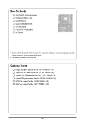
...Part No. 12CF1-2SERPW-0*R) S/PDIF In cable (Part No. 12CR1-1SPDIN-0*R) COM port cable (Part No. 12CF1-1CM001-3*R) - 6 - Box Contents GA-790XTA-UD4 motherboard Motherboard driver disk User's Manual Quick Installation Guide One IDE cable Four SATA 3Gb/s cables I/O Shield • The box contents above are subject to change ...without notice. • The motherboard image is for reference only and the actual items shall depend on the product package you obtain. The box contents are for reference only...
...Part No. 12CF1-2SERPW-0*R) S/PDIF In cable (Part No. 12CR1-1SPDIN-0*R) COM port cable (Part No. 12CF1-1CM001-3*R) - 6 - Box Contents GA-790XTA-UD4 motherboard Motherboard driver disk User's Manual Quick Installation Guide One IDE cable Four SATA 3Gb/s cables I/O Shield • The box contents above are subject to change ...without notice. • The motherboard image is for reference only and the actual items shall depend on the product package you obtain. The box contents are for reference only...
Manual
Page 7
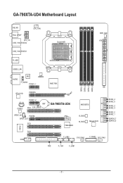
GA-790XTA-UD4 Motherboard Layout KB_MS CPU_FAN RCA_SPDIF ATX_12V USB_1394_ESATA2 USB_1394_ESATA1 Socket AM3 PWR_FAN ATX R_USB USB30_LAN AUDIO NEC JMB362 F_AUDIO PCIEX1_1 AMD 790X IDE RTL8111D PCIEX16 IT8720 DDR3_1 DDR3_2 DDR3_3 DDR3_4 CD_IN CODEC PCIEX1_2 BAT PCI1 CLR_CMOS GA-790XTA-UD4 SPDIF_IN PCIEX8 SPDIF_OUT PCI2 TSB43AB23 AMD SB750 B_BIOS M_BIOS Marvell 9128 SATA2_4 SATA2_5 SATA2_2 SATA2_3 SATA2_0 SATA2_1 GSATA3_7 GSATA3_6 PCI3 COM F_USB2 SYS_FAN2 F_PANEL SYS_FAN1 FDD F_1394 F_USB1 - 7 -
GA-790XTA-UD4 Motherboard Layout KB_MS CPU_FAN RCA_SPDIF ATX_12V USB_1394_ESATA2 USB_1394_ESATA1 Socket AM3 PWR_FAN ATX R_USB USB30_LAN AUDIO NEC JMB362 F_AUDIO PCIEX1_1 AMD 790X IDE RTL8111D PCIEX16 IT8720 DDR3_1 DDR3_2 DDR3_3 DDR3_4 CD_IN CODEC PCIEX1_2 BAT PCI1 CLR_CMOS GA-790XTA-UD4 SPDIF_IN PCIEX8 SPDIF_OUT PCI2 TSB43AB23 AMD SB750 B_BIOS M_BIOS Marvell 9128 SATA2_4 SATA2_5 SATA2_2 SATA2_3 SATA2_0 SATA2_1 GSATA3_7 GSATA3_6 PCI3 COM F_USB2 SYS_FAN2 F_PANEL SYS_FAN1 FDD F_1394 F_USB1 - 7 -
Manual
Page 9
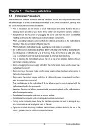
... uncertain about any installation steps or have a problem related to installation, do not remove or break motherboard S/N (Serial Number) sticker or warranty sticker provided by unplugging the power cord from the motherboard, make sure the power supply has been turned off. • Before turning on the power, ...casing. • Do not place the computer system on an uneven surface. • Do not place the computer system in contact with the motherboard circuit or its components. • Make sure there are required for warranty validation. • Always remove the AC power by your hands ...
... uncertain about any installation steps or have a problem related to installation, do not remove or break motherboard S/N (Serial Number) sticker or warranty sticker provided by unplugging the power cord from the motherboard, make sure the power supply has been turned off. • Before turning on the power, ...casing. • Do not place the computer system on an uneven surface. • Do not place the computer system in contact with the motherboard circuit or its components. • Make sure there are required for warranty validation. • Always remove the AC power by your hands ...
Manual
Page 12
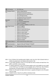
.... The PCIEX8 slot shares bandwidth with a PCI Express graphics card, the PCIEX16 slot will operate at up to install it in EasyTune may differ by motherboard model.
.... The PCIEX8 slot shares bandwidth with a PCI Express graphics card, the PCIEX16 slot will operate at up to install it in EasyTune may differ by motherboard model.
Manual
Page 13
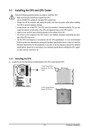
... socket.) • Apply an even and thin layer of thermal grease on the computer if the CPU cooler is not recommended that the motherboard supports the CPU. (Go to GIGABYTE's website for the latest CPU support list.) • Always turn on the surface of the CPU. Hardware Installation The CPU cannot be...
... socket.) • Apply an even and thin layer of thermal grease on the computer if the CPU cooler is not recommended that the motherboard supports the CPU. (Go to GIGABYTE's website for the latest CPU support list.) • Always turn on the surface of the CPU. Hardware Installation The CPU cannot be...
Manual
Page 14
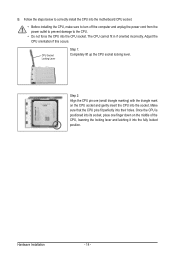
... the CPU socket. The CPU cannot fit in if oriented incorrectly. Hardware Installation - 14 - Follow the steps below to correctly install the CPU into the motherboard CPU socket. • Before installing the CPU, make sure to turn off the computer and unplug the power cord from the power outlet to prevent...
... the CPU socket. The CPU cannot fit in if oriented incorrectly. Hardware Installation - 14 - Follow the steps below to correctly install the CPU into the motherboard CPU socket. • Before installing the CPU, make sure to turn off the computer and unplug the power cord from the power outlet to prevent...
Manual
Page 15
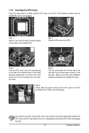
... the installed CPU. 1-3-2 Installing the CPU Cooler Follow the steps below to correctly install the CPU cooler on the CPU. (The following procedure uses the GIGABYTE cooler as the picture above shows) to lock into place. (Refer to your CPU cooler installation manual for instructions on installing the cooler.) Step 5: Finally...
... the installed CPU. 1-3-2 Installing the CPU Cooler Follow the steps below to correctly install the CPU cooler on the CPU. (The following procedure uses the GIGABYTE cooler as the picture above shows) to lock into place. (Refer to your CPU cooler installation manual for instructions on installing the cooler.) Step 5: Finally...
Manual
Page 16
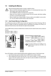
... of the memory. The four DDR3 memory sockets are unable to insert the memory, switch the direction. 1-4-1 Dual Channel Memory Configuration This motherboard provides four DDR3 memory sockets and supports Dual Channel Technology. Hardware Installation - 16 - DS/SS DS/SS Four Modules DS/SS DS/... is recommended that memory of the same capacity, brand, speed, and chips be enabled if only one direction. If you begin to GIGABYTE's website for optimum performance. Dual Channel mode cannot be used and installed in the same colored DDR3 sockets for the latest memory support list...
... of the memory. The four DDR3 memory sockets are unable to insert the memory, switch the direction. 1-4-1 Dual Channel Memory Configuration This motherboard provides four DDR3 memory sockets and supports Dual Channel Technology. Hardware Installation - 16 - DS/SS DS/SS Four Modules DS/SS DS/... is recommended that memory of the same capacity, brand, speed, and chips be enabled if only one direction. If you begin to GIGABYTE's website for optimum performance. Dual Channel mode cannot be used and installed in the same colored DDR3 sockets for the latest memory support list...
Manual
Page 17
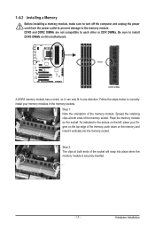
..., make sure to turn off the computer and unplug the power cord from the power outlet to prevent damage to install DDR3 DIMMs on this motherboard. Follow the steps below to correctly install your fingers on the top edge of the socket will snap into the memory socket. Notch DDR3 DIMM...
..., make sure to turn off the computer and unplug the power cord from the power outlet to prevent damage to install DDR3 DIMMs on this motherboard. Follow the steps below to correctly install your fingers on the top edge of the socket will snap into the memory socket. Notch DDR3 DIMM...
Manual
Page 18
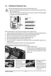
... the card and then lift the card straight out from the power outlet before you begin to install an expansion card: • Make sure the motherboard supports the expansion card. Turn on the card are completely inserted into the PCI Express slot. Make sure the card is fully seated in your...
... the card and then lift the card straight out from the power outlet before you begin to install an expansion card: • Make sure the motherboard supports the expansion card. Turn on the card are completely inserted into the PCI Express slot. Make sure the card is fully seated in your...
Manual
Page 19
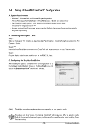
... card on top of your graphics cards for enabling CrossFireX technology may be needed or not depending on the PCI Express x16 slots. C. A CrossFireX-supported motherboard with your graphics cards. Refer to the manual of the two cards. Step 2: (Note) Insert the CrossFire bridge connectors in the CrossFireX gold edge connectors...
... card on top of your graphics cards for enabling CrossFireX technology may be needed or not depending on the PCI Express x16 slots. C. A CrossFireX-supported motherboard with your graphics cards. Refer to the manual of the two cards. Step 2: (Note) Insert the CrossFire bridge connectors in the CrossFireX gold edge connectors...
Manual
Page 20
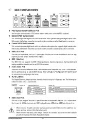
... - 20 - The following describes the states of the LAN port LEDs. Before using this feature, ensure that your device and then remove it from the motherboard. • When removing the cable, pull it side to side to an external audio system that supports digital optical audio. Use this port for an...
... - 20 - The following describes the states of the LAN port LEDs. Before using this feature, ensure that your device and then remove it from the motherboard. • When removing the cable, pull it side to side to an external audio system that supports digital optical audio. Use this port for an...
Manual
Page 22
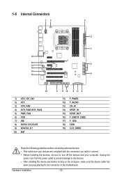
... 12) F_AUDIO 13) CD_IN 14) SPDIF_IN 15) SPDIF_OUT 16) F_USB1/F_USB2 17) F_1394 18) COM 19) CLR_CMOS Read the following guidelines before turning on the motherboard.
... 12) F_AUDIO 13) CD_IN 14) SPDIF_IN 15) SPDIF_OUT 16) F_USB1/F_USB2 17) F_1394 18) COM 19) CLR_CMOS Read the following guidelines before turning on the motherboard.
Manual
Page 23
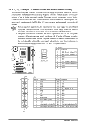
... power supply providing a 2x4 12V and a 2x12 power connector, remove the protective covers from the 12V power connector and the main power connector on the motherboard. When using a power supply providing a 2x2 12V and a 2x10 power connector. 8 4 5 1 ATX_12V_2X4 ATX_12V_2X4: Pin No. Hardware Installation If the ... devices are compatible with power supplies with 2x2 12V and 2x10 power connectors. If a power supply is turned off and all the components on the motherboard. Definition 1 GND (Only for 2x4-pin 12V) 2 GND (Only for 2x4-pin 12V) 3 GND 4 GND 5 +12V (Only for 2x4-pin ...
... power supply providing a 2x4 12V and a 2x12 power connector, remove the protective covers from the 12V power connector and the main power connector on the motherboard. When using a power supply providing a 2x2 12V and a 2x10 power connector. 8 4 5 1 ATX_12V_2X4 ATX_12V_2X4: Pin No. Hardware Installation If the ... devices are compatible with power supplies with 2x2 12V and 2x10 power connectors. If a power supply is turned off and all the components on the motherboard. Definition 1 GND (Only for 2x4-pin 12V) 2 GND (Only for 2x4-pin 12V) 3 GND 4 GND 5 +12V (Only for 2x4-pin ...
Manual
Page 24
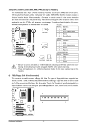
... Sense 4 Reserve 1 1 SYS_FAN2 PWR_FAN SYS_FAN2/PWR_FAN: Pin No. Before connecting a floppy disk drive, be installed inside the chassis. The motherboard supports CPU fan speed control, which requires the use of floppy disk drives supported are not configuration jumper blocks. The types of a CPU... fan with fan speed control design. 3/4/5) CPU_FAN/SYS_FAN1/SYS_FAN2/PWR_FAN (Fan Headers) The motherboard has a 4-pin CPU fan header (CPU_FAN), a 3-pin (SYS_FAN2) and a 4-pin (SYS_ FAN1) system fan headers, and a 3-pin power...
... Sense 4 Reserve 1 1 SYS_FAN2 PWR_FAN SYS_FAN2/PWR_FAN: Pin No. Before connecting a floppy disk drive, be installed inside the chassis. The motherboard supports CPU fan speed control, which requires the use of floppy disk drives supported are not configuration jumper blocks. The types of a CPU... fan with fan speed control design. 3/4/5) CPU_FAN/SYS_FAN1/SYS_FAN2/PWR_FAN (Fan Headers) The motherboard has a 4-pin CPU fan header (CPU_FAN), a 3-pin (SYS_FAN2) and a 4-pin (SYS_ FAN1) system fan headers, and a 3-pin power...
Manual
Page 28
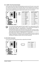
... a front panel audio module that came with your optical drive to this header. Pin No. Incorrect connection between the module connector and the motherboard header will make the device unable to activate AC'97 functionality via the audio software in Chapter 5, "Configuring 2/4/5.1/7.1-Channel Audio." • Audio...connect your chassis provides an AC'97 front panel audio module, refer to the instructions on each wire instead of the motherboard header. 12) F_AUDIO (Front Panel Audio Header) The front panel audio header supports Intel High Definition audio (HD) and AC'97 audio.
... a front panel audio module that came with your optical drive to this header. Pin No. Incorrect connection between the module connector and the motherboard header will make the device unable to activate AC'97 functionality via the audio software in Chapter 5, "Configuring 2/4/5.1/7.1-Channel Audio." • Audio...connect your chassis provides an AC'97 front panel audio module, refer to the instructions on each wire instead of the motherboard header. 12) F_AUDIO (Front Panel Audio Header) The front panel audio header supports Intel High Definition audio (HD) and AC'97 audio.


