Manual
Page 1
GA-770T-USB3 AM3 socket motherboard for AMD Phenom™ II processor/ AMD Athlon™ II processor User's Manual Rev. 1001 12ME-770TB3-1001R
GA-770T-USB3 AM3 socket motherboard for AMD Phenom™ II processor/ AMD Athlon™ II processor User's Manual Rev. 1001 12ME-770TB3-1001R

Manual
Page 2
Motherboard GA-770T-USB3 Jan. 8, 2010 Motherboard GA-770T-USB3 Jan. 8, 2010
Motherboard GA-770T-USB3 Jan. 8, 2010 Motherboard GA-770T-USB3 Jan. 8, 2010
Manual
Page 3
... manual may be made by copyright laws and is 1.0. The trademarks mentioned in the use GIGABYTE's unique features, read or download the information on/from the Support&Downloads\Motherboard\Technology Guide page on your motherboard revision before updating motherboard BIOS, drivers, or when looking for technical information. Changes to the specifications and features in...
... manual may be made by copyright laws and is 1.0. The trademarks mentioned in the use GIGABYTE's unique features, read or download the information on/from the Support&Downloads\Motherboard\Technology Guide page on your motherboard revision before updating motherboard BIOS, drivers, or when looking for technical information. Changes to the specifications and features in...
Manual
Page 4
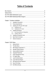
Table of Contents Box Contents...6 Optional Items...6 GA-770T-USB3 Motherboard Layout 7 GA-770T-USB3 Motherboard Block Diagram 8 Chapter 1 Hardware Installation 9 1-1 Installation Precautions 9 1-2 Product Specifications 10 1-3 Installing the CPU and CPU Cooler 13 1-3-1 Installing the CPU 13 1-3-2 Installing the CPU Cooler ...
Table of Contents Box Contents...6 Optional Items...6 GA-770T-USB3 Motherboard Layout 7 GA-770T-USB3 Motherboard Block Diagram 8 Chapter 1 Hardware Installation 9 1-1 Installation Precautions 9 1-2 Product Specifications 10 1-3 Installing the CPU and CPU Cooler 13 1-3-1 Installing the CPU 13 1-3-2 Installing the CPU Cooler ...
Manual
Page 6
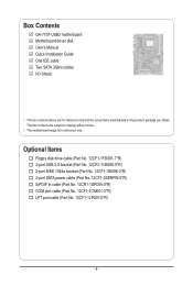
.... 12CF1-2SERPW-0*R) S/PDIF In cable (Part No. 12CR1-1SPDIN-0*R) COM port cable (Part No. 12CF1-1CM001-3*R) LPT port cable (Part No. 12CF1-1LP001-0*R) - 6 - Box Contents GA-770T-USB3 motherboard Motherboard driver disk User's Manual Quick Installation Guide One IDE cable Two SATA 3Gb/s cables I/O Shield • The box contents above are subject to change without...
.... 12CF1-2SERPW-0*R) S/PDIF In cable (Part No. 12CR1-1SPDIN-0*R) COM port cable (Part No. 12CF1-1CM001-3*R) LPT port cable (Part No. 12CF1-1LP001-0*R) - 6 - Box Contents GA-770T-USB3 motherboard Motherboard driver disk User's Manual Quick Installation Guide One IDE cable Two SATA 3Gb/s cables I/O Shield • The box contents above are subject to change without...
Manual
Page 7
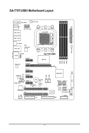
GA-770T-USB3 Motherboard Layout KB_MS SYS_FAN2 CPU_FAN RCA_SPDIF ATX ATX_12V_2X4 USB_1394_1 Socket AM3 USB_1394_2 R_USB30 USB_LAN NEC D720200F1 PWR_FAN F_AUDIO AUDIO PCIEX1_1 RTL8111D PCIEX16 GA-770T-USB3 AMD 770 DDR3_1 DDR3_2 DDR3_3 DDR3_4 PCIEX1_2 CD_IN SPDIF_IN CODEC PCIEX1_3 SPDIF_OUT PCIEX1_4 BAT M_BIOS B_BIOS CLR_CMOS PCI1 TSB43AB23 PCI2 F_1394 LPT F_USB1 F_USB2 IDE AMD SB710 SATA2_1 SATA2_3 IT8720 SATA2_0 SATA2_2 SATA2_5 SATA2_4 SYS_FAN1 F_PANEL FDD COMA - 7 -
GA-770T-USB3 Motherboard Layout KB_MS SYS_FAN2 CPU_FAN RCA_SPDIF ATX ATX_12V_2X4 USB_1394_1 Socket AM3 USB_1394_2 R_USB30 USB_LAN NEC D720200F1 PWR_FAN F_AUDIO AUDIO PCIEX1_1 RTL8111D PCIEX16 GA-770T-USB3 AMD 770 DDR3_1 DDR3_2 DDR3_3 DDR3_4 PCIEX1_2 CD_IN SPDIF_IN CODEC PCIEX1_3 SPDIF_OUT PCIEX1_4 BAT M_BIOS B_BIOS CLR_CMOS PCI1 TSB43AB23 PCI2 F_1394 LPT F_USB1 F_USB2 IDE AMD SB710 SATA2_1 SATA2_3 IT8720 SATA2_0 SATA2_2 SATA2_5 SATA2_4 SYS_FAN1 F_PANEL FDD COMA - 7 -
Manual
Page 8
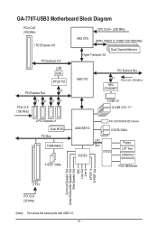
GA-770T-USB3 Motherboard Block Diagram PCIe CLK (100 MHz) 1 PCI Express x16 PCI Express x16 LAN RJ45 RTL8111D x1 PCI Express Bus CPU CLK+/- (200 MHz) AM3 CPU ...
GA-770T-USB3 Motherboard Block Diagram PCIe CLK (100 MHz) 1 PCI Express x16 PCI Express x16 LAN RJ45 RTL8111D x1 PCI Express Bus CPU CLK+/- (200 MHz) AM3 CPU ...
Manual
Page 9
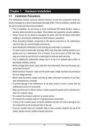
...not have an ESD wrist strap, keep your hands dry and first touch a metal object to eliminate static electricity. • Prior to installing the motherboard, please have a problem related to the use of the product, please consult a certified computer technician. - 9 - These stickers are required for warranty...system on an uneven surface. • Do not place the computer system in a high-temperature environment. • Turning on the motherboard, make sure the power supply voltage has been set according to the internal connectors on the computer power during the installation process can ...
...not have an ESD wrist strap, keep your hands dry and first touch a metal object to eliminate static electricity. • Prior to installing the motherboard, please have a problem related to the use of the product, please consult a certified computer technician. - 9 - These stickers are required for warranty...system on an uneven surface. • Do not place the computer system in a high-temperature environment. • Turning on the motherboard, make sure the power supply voltage has been set according to the internal connectors on the computer power during the installation process can ...
Manual
Page 12
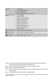
... CPU/system fan speed control function is supported will depend on the CPU/system cooler you install. (Note 5) Available functions in EasyTune may differ by motherboard model.
... CPU/system fan speed control function is supported will depend on the CPU/system cooler you install. (Note 5) Available functions in EasyTune may differ by motherboard model.
Manual
Page 13
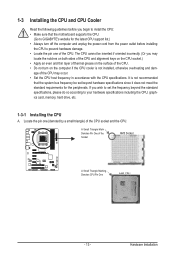
... the computer and unplug the power cord from the power outlet before you begin to install the CPU: • Make sure that the motherboard supports the CPU. (Go to GIGABYTE's website for the peripherals. If you wish to set beyond the standard specifications, please do so according to your hardware specifications including...
... the computer and unplug the power cord from the power outlet before you begin to install the CPU: • Make sure that the motherboard supports the CPU. (Go to GIGABYTE's website for the peripherals. If you wish to set beyond the standard specifications, please do so according to your hardware specifications including...
Manual
Page 14
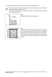
... into their holes. Hardware Installation - 14 - The CPU cannot fit in if oriented incorrectly. Follow the steps below to correctly install the CPU into the motherboard CPU socket. • Before installing the CPU, make sure to turn off the computer and unplug the power cord from the power outlet to prevent...
... into their holes. Hardware Installation - 14 - The CPU cannot fit in if oriented incorrectly. Follow the steps below to correctly install the CPU into the motherboard CPU socket. • Before installing the CPU, make sure to turn off the computer and unplug the power cord from the power outlet to prevent...
Manual
Page 15
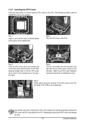
Step 3: Hook the CPU cooler clip to the mounting lug on the motherboard. Step 4: Turn the cam handle from the left side to the right side (as the example.) Step 1: Apply an even and thin layer of thermal ... on the CPU. 1-3-2 Installing the CPU Cooler Follow the steps below to correctly install the CPU cooler on the CPU. (The following procedure uses the GIGABYTE cooler as the picture above shows) to lock into place. (Refer to your CPU cooler installation manual for instructions on installing the cooler.) Step 5: Finally...
Step 3: Hook the CPU cooler clip to the mounting lug on the motherboard. Step 4: Turn the cam handle from the left side to the right side (as the example.) Step 1: Apply an even and thin layer of thermal ... on the CPU. 1-3-2 Installing the CPU Cooler Follow the steps below to correctly install the CPU cooler on the CPU. (The following procedure uses the GIGABYTE cooler as the picture above shows) to lock into place. (Refer to your CPU cooler installation manual for instructions on installing the cooler.) Step 5: Finally...

Manual
Page 16
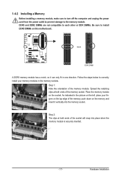
...installing the memory in Dual Channel mode. 1. Dual Channel mode cannot be enabled if only one DDR3 memory module is recommended that the motherboard supports the memory. It is installed. 2. Enabling Dual Channel memory mode will automatically detect the specifications and capacity of the same capacity,...DDR3_3 DDR3_4 Due to install the memory: • Make sure that memory of the memory. The four DDR3 memory sockets are unable to GIGABYTE's website for optimum performance. A memory module can be used and installed in the same colored DDR3 sockets for the latest memory support ...
...installing the memory in Dual Channel mode. 1. Dual Channel mode cannot be enabled if only one DDR3 memory module is recommended that the motherboard supports the memory. It is installed. 2. Enabling Dual Channel memory mode will automatically detect the specifications and capacity of the same capacity,...DDR3_3 DDR3_4 Due to install the memory: • Make sure that memory of the memory. The four DDR3 memory sockets are unable to GIGABYTE's website for optimum performance. A memory module can be used and installed in the same colored DDR3 sockets for the latest memory support ...
Manual
Page 17
..., make sure to turn off the computer and unplug the power cord from the power outlet to prevent damage to install DDR3 DIMMs on this motherboard. Step 1: Note the orientation of the memory socket. As indicated in the picture on the left, place your memory modules in one direction. DDR3 and...
..., make sure to turn off the computer and unplug the power cord from the power outlet to prevent damage to install DDR3 DIMMs on this motherboard. Step 1: Note the orientation of the memory socket. As indicated in the picture on the left, place your memory modules in one direction. DDR3 and...
Manual
Page 18
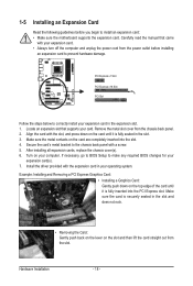
... turn off the computer and unplug the power cord from the power outlet before you begin to install an expansion card: • Make sure the motherboard supports the expansion card. 1-5 Installing an Expansion Card Read the following guidelines before installing an expansion card to prevent hardware damage. Align the card with...
... turn off the computer and unplug the power cord from the power outlet before you begin to install an expansion card: • Make sure the motherboard supports the expansion card. 1-5 Installing an Expansion Card Read the following guidelines before installing an expansion card to prevent hardware damage. Align the card with...
Manual
Page 19
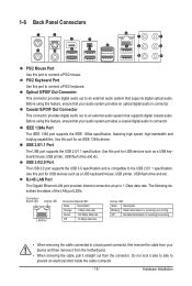
... LAN port provides Internet connection at up to an external audio system that supports digital optical audio. Do not rock it straight out from the motherboard. • When removing the cable, pull it side to side to an external audio system that supports digital coaxial audio. Use this port to a back...
... LAN port provides Internet connection at up to an external audio system that supports digital optical audio. Do not rock it straight out from the motherboard. • When removing the cable, pull it side to side to an external audio system that supports digital coaxial audio. Use this port to a back...
Manual
Page 21
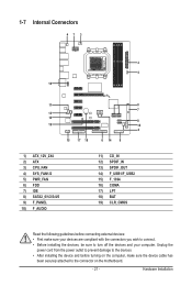
...) 13) 14) 15) 16) 17) 18) 19) CD_IN SPDIF_IN SPDIF_OUT F_USB1/F_USB2 F_1394 COMA LPT BAT CLR_CMOS Read the following guidelines before turning on the motherboard. - 21 - Hardware Installation Unplug the power cord from the power outlet to prevent damage to the devices. • After installing the device and before connecting...
...) 13) 14) 15) 16) 17) 18) 19) CD_IN SPDIF_IN SPDIF_OUT F_USB1/F_USB2 F_1394 COMA LPT BAT CLR_CMOS Read the following guidelines before turning on the motherboard. - 21 - Hardware Installation Unplug the power cord from the power outlet to prevent damage to the devices. • After installing the device and before connecting...

Manual
Page 22
... power to all devices are properly installed. The power connector possesses a foolproof design. If a power supply is turned off and all the components on the motherboard. To meet expansion requirements, it is not connected, the computer will not start. 1/2) ATX_12V_2X4/ATX (2x4 12V Power Connector and 2x12 Main Power Connector) With...
... power to all devices are properly installed. The power connector possesses a foolproof design. If a power supply is turned off and all the components on the motherboard. To meet expansion requirements, it is not connected, the computer will not start. 1/2) ATX_12V_2X4/ATX (2x4 12V Power Connector and 2x12 Main Power Connector) With...
Manual
Page 23
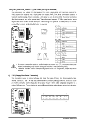
The pin 1 of the cable is the ground wire). Hardware Installation 3/4/5) CPU_FAN/SYS_FAN1/SYS_FAN2/PWR_FAN (Fan Headers) The motherboard has a 4-pin CPU fan header (CPU_FAN), a 4-pin (SYS_FAN1) and one 3-pin (SYS_ FAN2) system fan headers, and a 3-pin power fan header (... in the correct orientation (the black connector wire is typically designated by a stripe of the connector and the floppy disk drive cable. The motherboard supports CPU fan speed control, which requires the use of floppy disk drives supported are not configuration jumper blocks. Overheating may hang. •...
The pin 1 of the cable is the ground wire). Hardware Installation 3/4/5) CPU_FAN/SYS_FAN1/SYS_FAN2/PWR_FAN (Fan Headers) The motherboard has a 4-pin CPU fan header (CPU_FAN), a 4-pin (SYS_FAN1) and one 3-pin (SYS_ FAN2) system fan headers, and a 3-pin power fan header (... in the correct orientation (the black connector wire is typically designated by a stripe of the connector and the floppy disk drive cable. The motherboard supports CPU fan speed control, which requires the use of floppy disk drives supported are not configuration jumper blocks. Overheating may hang. •...
Manual
Page 26
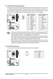
... module), refer to work or even damage it. Make sure the wire assignments of the module connector match the pin assignments of the motherboard header. 10) F_AUDIO (Front Panel Audio Header) The front panel audio header supports Intel High Definition audio (HD) and AC'97... LINE2_R 6 GND 7 FAUDIO_JD 8 No Pin 9 LINE2_L 10 GND For AC'97 Front Panel Audio: Pin No. Incorrect connection between the module connector and the motherboard header will be present on each wire instead of the front and back panel audio connections simultaneously. Definition 1 CD-L 2 GND 3 GND 1 4 CD-R Hardware...
... module), refer to work or even damage it. Make sure the wire assignments of the module connector match the pin assignments of the motherboard header. 10) F_AUDIO (Front Panel Audio Header) The front panel audio header supports Intel High Definition audio (HD) and AC'97... LINE2_R 6 GND 7 FAUDIO_JD 8 No Pin 9 LINE2_L 10 GND For AC'97 Front Panel Audio: Pin No. Incorrect connection between the module connector and the motherboard header will be present on each wire instead of the front and back panel audio connections simultaneously. Definition 1 CD-L 2 GND 3 GND 1 4 CD-R Hardware...


