Manual
Page 3
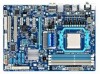
... the following types of documentations: For quick set-up of GIGABYTE. For example, "REV: 1.0" means the revision of the motherboard is the property of the product, read the Quick Installation Guide included with the product. No part of this manual is protected by any means without... prior notice. For product-related information, check on our website at: http://www.gigabyte.com.tw Identifying Your Motherboard Revision The ...
... the following types of documentations: For quick set-up of GIGABYTE. For example, "REV: 1.0" means the revision of the motherboard is the property of the product, read the Quick Installation Guide included with the product. No part of this manual is protected by any means without... prior notice. For product-related information, check on our website at: http://www.gigabyte.com.tw Identifying Your Motherboard Revision The ...
Manual
Page 4
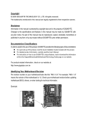
Table of Contents Box Contents...6 Optional Items...6 GA-770T-USB3 Motherboard Layout 7 GA-770T-USB3 Motherboard Block Diagram 8 Chapter 1 Hardware Installation 9 1-1 Installation Precautions 9 1-2 Product Specifications 10 1-3 Installing the CPU and CPU Cooler 13 1-3-1 Installing the CPU 13 1-3-2 Installing the CPU Cooler 15 1-4 Installing the Memory 16 1-4-1 Dual Channel Memory Configuration 16 1-4-2 Installing a Memory 17 1-5 Installing an Expansion Card 18 1-6 Back Panel Connectors 19 1-7 Internal Connectors...
Table of Contents Box Contents...6 Optional Items...6 GA-770T-USB3 Motherboard Layout 7 GA-770T-USB3 Motherboard Block Diagram 8 Chapter 1 Hardware Installation 9 1-1 Installation Precautions 9 1-2 Product Specifications 10 1-3 Installing the CPU and CPU Cooler 13 1-3-1 Installing the CPU 13 1-3-2 Installing the CPU Cooler 15 1-4 Installing the Memory 16 1-4-1 Dual Channel Memory Configuration 16 1-4-2 Installing a Memory 17 1-5 Installing an Expansion Card 18 1-6 Back Panel Connectors 19 1-7 Internal Connectors...

Manual
Page 5
Chapter 3 Drivers Installation 55 3-1 Installing Chipset Drivers 55 3-2 Application Software 56 3-3 Technical Manuals 56 3-4 Contact...57 3-5 System...57 3-6 Download Center 58 Chapter 4 Unique Features 59 4-1 Xpress ...Recovery 70 Chapter 5 Appendix...71 5-1 Configuring SATA Hard Drive(s 71 5-1-1 Configuring AMD SB710 SATA Controller 71 5-1-2 Making a SATA RAID/AHCI Driver Diskette 77 5-1-3 Installing the SATA RAID/AHCI Driver and Operating System 79 5-2 Configuring Audio Input and Output 83 5-2-1 Configuring 2/4/5.1/7.1-Channel Audio 83 5-2-2 Configuring S/PDIF In/Out 85 5-2-3...
Chapter 3 Drivers Installation 55 3-1 Installing Chipset Drivers 55 3-2 Application Software 56 3-3 Technical Manuals 56 3-4 Contact...57 3-5 System...57 3-6 Download Center 58 Chapter 4 Unique Features 59 4-1 Xpress ...Recovery 70 Chapter 5 Appendix...71 5-1 Configuring SATA Hard Drive(s 71 5-1-1 Configuring AMD SB710 SATA Controller 71 5-1-2 Making a SATA RAID/AHCI Driver Diskette 77 5-1-3 Installing the SATA RAID/AHCI Driver and Operating System 79 5-2 Configuring Audio Input and Output 83 5-2-1 Configuring 2/4/5.1/7.1-Channel Audio 83 5-2-2 Configuring S/PDIF In/Out 85 5-2-3...
Manual
Page 6
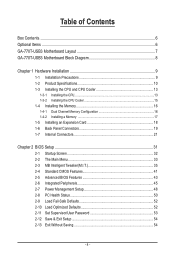
... cable (Part No. 12CR1-1SPDIN-0*R) COM port cable (Part No. 12CF1-1CM001-3*R) LPT port cable (Part No. 12CF1-1LP001-0*R) - 6 - Box Contents GA-770T-USB3 motherboard Motherboard driver disk User's Manual Quick Installation Guide One IDE cable Two SATA 3Gb/s cables I/O Shield • The box contents above are subject to change without notice. • The...
... cable (Part No. 12CR1-1SPDIN-0*R) COM port cable (Part No. 12CF1-1CM001-3*R) LPT port cable (Part No. 12CF1-1LP001-0*R) - 6 - Box Contents GA-770T-USB3 motherboard Motherboard driver disk User's Manual Quick Installation Guide One IDE cable Two SATA 3Gb/s cables I/O Shield • The box contents above are subject to change without notice. • The...
Manual
Page 9
...that all cables and power connectors of your hands dry and first touch a metal object to eliminate static electricity. • Prior to installing the motherboard, please have a problem related to wear an electrostatic discharge (ESD) wrist strap when handling electronic com- If you are connected... tightly and securely. • When handling the motherboard, avoid touching any installation steps or have it on top of an antistatic pad or within an electrostatic shielding container. • Before unplugging the power supply ...
...that all cables and power connectors of your hands dry and first touch a metal object to eliminate static electricity. • Prior to installing the motherboard, please have a problem related to wear an electrostatic discharge (ESD) wrist strap when handling electronic com- If you are connected... tightly and securely. • When handling the motherboard, avoid touching any installation steps or have it on top of an antistatic pad or within an electrostatic shielding container. • Before unplugging the power supply ...

Manual
Page 10
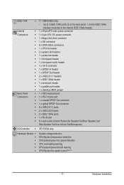
... (Note 3) (8 on the back panel, 4 via the USB brackets connected to 2 USB 3.0 ports on the back panel Hardware Installation - 10 - Up to the internal USB headers) NEC D720200F1 chip - 1-2 Product Specifications CPU Support for AM3 processors:... AMD Phenom™ II processor/ AMD Athlon™ II processor (Go to GIGABYTE's website for the latest CPU support list.) Hyper Transport Bus 5200 MT/s Chipset Memory ...
... (Note 3) (8 on the back panel, 4 via the USB brackets connected to 2 USB 3.0 ports on the back panel Hardware Installation - 10 - Up to the internal USB headers) NEC D720200F1 chip - 1-2 Product Specifications CPU Support for AM3 processors:... AMD Phenom™ II processor/ AMD Athlon™ II processor (Go to GIGABYTE's website for the latest CPU support list.) Hyper Transport Bus 5200 MT/s Chipset Memory ...
Manual
Page 11
TSB43AB23 chip: - Hardware Installation IEEE 1394 T.I /O Controller w iTE IT8720 chip Hardware Monitor w w w w w w System voltage detection CPU/System temperature detection CPU/system/power fan speed detection CPU overheating warning ...
TSB43AB23 chip: - Hardware Installation IEEE 1394 T.I /O Controller w iTE IT8720 chip Hardware Monitor w w w w w w System voltage detection CPU/System temperature detection CPU/system/power fan speed detection CPU overheating warning ...
Manual
Page 12
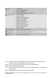
..., DMI 2.0, SM BIOS 2.4, ACPI 1.0b Support for @BIOS Support for Q-Flash Support for Xpress BIOS Rescue Support for Download Center Support for Xpress Install Support for Xpress Recovery2 Support for EasyTune (Note 5) Support for Easy Energy Saver Support for Smart Recovery Support for Q-Share Norton Internet Security (OEM version...Form Factor; 30.5cm x 22.0cm (Note 1) Due to Windows 32-bit operating system limitation, when more than 4 GB of physical memory is installed, the actual memory size displayed will be less than 4 GB. (Note 2) Use of a CPU that supports ECC is required if you wish to...
..., DMI 2.0, SM BIOS 2.4, ACPI 1.0b Support for @BIOS Support for Q-Flash Support for Xpress BIOS Rescue Support for Download Center Support for Xpress Install Support for Xpress Recovery2 Support for EasyTune (Note 5) Support for Easy Energy Saver Support for Smart Recovery Support for Q-Share Norton Internet Security (OEM version...Form Factor; 30.5cm x 22.0cm (Note 1) Due to Windows 32-bit operating system limitation, when more than 4 GB of physical memory is installed, the actual memory size displayed will be less than 4 GB. (Note 2) Use of a CPU that supports ECC is required if you wish to...
Manual
Page 13
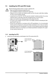
... a small triangle) of the CPU. • Do not turn off the computer and unplug the power cord from the power outlet before you begin to install the CPU: • Make sure that the system bus frequency be inserted if oriented incorrectly. (Or you may occur. • Set the CPU host frequency... even and thin layer of thermal grease on the computer if the CPU cooler is not recommended that the motherboard supports the CPU. (Go to GIGABYTE's website for the peripherals. Locate the pin one of the Socket AM3 Socket A Small Triangle Marking Denotes CPU Pin One AM3 CPU - 13...
... a small triangle) of the CPU. • Do not turn off the computer and unplug the power cord from the power outlet before you begin to install the CPU: • Make sure that the system bus frequency be inserted if oriented incorrectly. (Or you may occur. • Set the CPU host frequency... even and thin layer of thermal grease on the computer if the CPU cooler is not recommended that the motherboard supports the CPU. (Go to GIGABYTE's website for the peripherals. Locate the pin one of the Socket AM3 Socket A Small Triangle Marking Denotes CPU Pin One AM3 CPU - 13...
Manual
Page 14
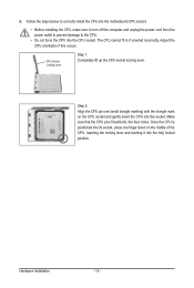
...oriented incorrectly. Step 2: Align the CPU pin one finger down on the CPU socket and gently insert the CPU into the fully locked position. Hardware Installation - 14 - Once the CPU is positioned into its socket, place one (small triangle marking) with the triangle mark on the middle of the CPU..., lowering the locking lever and latching it into the socket. Follow the steps below to correctly install the CPU into the motherboard CPU socket. • Before installing the CPU, make sure to turn off the computer and unplug the power cord from the power outlet to prevent...
...oriented incorrectly. Step 2: Align the CPU pin one finger down on the CPU socket and gently insert the CPU into the fully locked position. Hardware Installation - 14 - Once the CPU is positioned into its socket, place one (small triangle marking) with the triangle mark on the middle of the CPU..., lowering the locking lever and latching it into the socket. Follow the steps below to correctly install the CPU into the motherboard CPU socket. • Before installing the CPU, make sure to turn off the computer and unplug the power cord from the power outlet to prevent...
Manual
Page 15
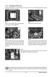
.../tape between the CPU cooler and CPU may damage the CPU. - 15 - 1-3-2 Installing the CPU Cooler Follow the steps below to correctly install the CPU cooler on the CPU. (The following procedure uses the GIGABYTE cooler as the picture above shows) to lock into place. (Refer to your CPU ...cooler installation manual for instructions on installing the cooler.) Step 5: Finally, attach the power connector of the installed CPU. On the other side,push straight down on...
.../tape between the CPU cooler and CPU may damage the CPU. - 15 - 1-3-2 Installing the CPU Cooler Follow the steps below to correctly install the CPU cooler on the CPU. (The following procedure uses the GIGABYTE cooler as the picture above shows) to lock into place. (Refer to your CPU ...cooler installation manual for instructions on installing the cooler.) Step 5: Finally, attach the power connector of the installed CPU. On the other side,push straight down on...

Manual
Page 16
... modules are divided into two channels and each channel has two memory sockets as following guidelines before installing the memory to GIGABYTE's website for optimum performance. DDR3_1 DDR3_2 DDR3_3 DDR3_4 Due to be installed, it is installed, the BIOS will double the original memory bandwidth. When enabling Dual Channel mode with two or four...
... modules are divided into two channels and each channel has two memory sockets as following guidelines before installing the memory to GIGABYTE's website for optimum performance. DDR3_1 DDR3_2 DDR3_3 DDR3_4 Due to be installed, it is installed, the BIOS will double the original memory bandwidth. When enabling Dual Channel mode with two or four...
Manual
Page 17
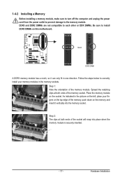
Step 2: The clips at both ends of the memory, push down on the memory and insert it can only fit in the memory sockets. Hardware Installation Notch DDR3 DIMM A DDR3 memory module has a notch, so it vertically into place when the memory module is securely inserted. - 17 - Follow the ...steps below to correctly install your fingers on the left, place your memory modules in one direction. As indicated in the picture on the top edge of the socket will...
Step 2: The clips at both ends of the memory, push down on the memory and insert it can only fit in the memory sockets. Hardware Installation Notch DDR3 DIMM A DDR3 memory module has a notch, so it vertically into place when the memory module is securely inserted. - 17 - Follow the ...steps below to correctly install your fingers on the left, place your memory modules in one direction. As indicated in the picture on the top edge of the socket will...
Manual
Page 18
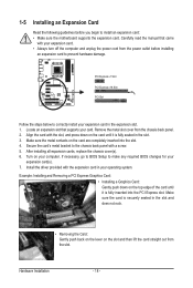
...; Always turn off the computer and unplug the power cord from the power outlet before you begin to install an expansion card: • Make sure the motherboard supports the expansion card. Hardware Installation - 18 - Secure the card's metal bracket to the chassis back panel with your expansion card(s). 7.... Gently push down on the card until it is securely seated in the slot. 3. Remove the metal slot cover from the slot. After installing all expansion cards, replace the chassis cover(s). 6. Turn on the slot and then lift the card straight out from the chassis back panel. ...
...; Always turn off the computer and unplug the power cord from the power outlet before you begin to install an expansion card: • Make sure the motherboard supports the expansion card. Hardware Installation - 18 - Secure the card's metal bracket to the chassis back panel with your expansion card(s). 7.... Gently push down on the card until it is securely seated in the slot. 3. Remove the metal slot cover from the slot. After installing all expansion cards, replace the chassis cover(s). 6. Turn on the slot and then lift the card straight out from the chassis back panel. ...
Manual
Page 19
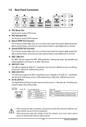
... etc. 1-6 Back Panel Connectors PS/2 Mouse Port Use this port to connect a PS/2 keyboard. PS/2 Keyboard Port Use this port to 1 Gbps data rate. Hardware Installation USB 2.0/1.1 Port The USB port supports the USB 2.0/1.1 specification. Use this port for USB devices such as a USB keyboard/mouse, USB printer, USB flash drive...
... etc. 1-6 Back Panel Connectors PS/2 Mouse Port Use this port to connect a PS/2 keyboard. PS/2 Keyboard Port Use this port to 1 Gbps data rate. Hardware Installation USB 2.0/1.1 Port The USB port supports the USB 2.0/1.1 specification. Use this port for USB devices such as a USB keyboard/mouse, USB printer, USB flash drive...

Manual
Page 20
Use this audio jack for a headphone or 2-channel speaker. Use this audio jack for line in devices such as an optical drive, walkman, etc. Hardware Installation - 20 - Center/Subwoofer Speaker Out Jack (Orange) Use this jack. Microphones must be reconfigured to the default Mic in jack. This jack can be connected ...
Use this audio jack for a headphone or 2-channel speaker. Use this audio jack for line in devices such as an optical drive, walkman, etc. Hardware Installation - 20 - Center/Subwoofer Speaker Out Jack (Orange) Use this jack. Microphones must be reconfigured to the default Mic in jack. This jack can be connected ...
Manual
Page 21
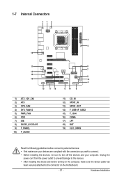
... the power cord from the power outlet to prevent damage to the devices. • After installing the device and before connecting external devices: • First make sure the device cable has been securely attached to turn off the devices and your ...devices are compliant with the connectors you wish to connect. • Before installing the devices, be sure to the connector on the computer, make sure your computer. 1-7 Internal Connectors 41 3 2 5 10 11 8 7 13 12 8 19 16 4 15 17...
... the power cord from the power outlet to prevent damage to the devices. • After installing the device and before connecting external devices: • First make sure the device cable has been securely attached to turn off the devices and your ...devices are compliant with the connectors you wish to connect. • Before installing the devices, be sure to the connector on the computer, make sure your computer. 1-7 Internal Connectors 41 3 2 5 10 11 8 7 13 12 8 19 16 4 15 17...

Manual
Page 22
... supply that does not provide the required power, the result can withstand high power consumption be used that can lead to all devices are properly installed. If the 12V power connector is turned off and all the components on the motherboard. Connect the power supply cable to the CPU. The 12V... -12V GND PS_ON (soft On/Off) GND GND GND -5V +5V +5V +5V (Only for 2x12-pin ATX) GND (Only for 2x12-pin ATX) Hardware Installation - 22 - 1/2) ATX_12V_2X4/ATX (2x4 12V Power Connector and 2x12 Main Power Connector) With the use of the power connector, the power supply can supply enough...
... supply that does not provide the required power, the result can withstand high power consumption be used that can lead to all devices are properly installed. If the 12V power connector is turned off and all the components on the motherboard. Connect the power supply cable to the CPU. The 12V... -12V GND PS_ON (soft On/Off) GND GND GND -5V +5V +5V +5V (Only for 2x12-pin ATX) GND (Only for 2x12-pin ATX) Hardware Installation - 22 - 1/2) ATX_12V_2X4/ATX (2x4 12V Power Connector and 2x12 Main Power Connector) With the use of the power connector, the power supply can supply enough...
Manual
Page 23
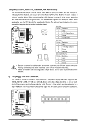
... drive cable. Definition 1 GND 2 +12V 3 Sense • Be sure to connect fan cables to the fan headers to connect a floppy disk drive. Hardware Installation The motherboard supports CPU fan speed control, which requires the use of different color. The pin 1 of the cable is used to prevent your CPU... may result in damage to connect it is the ground wire). Most fan headers possess a foolproof insertion design. When connecting a fan cable, be installed inside the chassis. Definition 1 CPU_FAN 1 GND 2 +12V / Speed Control 3 Sense 4 Speed Control SYS_FAN1: Pin No.
... drive cable. Definition 1 GND 2 +12V 3 Sense • Be sure to connect fan cables to the fan headers to connect a floppy disk drive. Hardware Installation The motherboard supports CPU fan speed control, which requires the use of different color. The pin 1 of the cable is used to prevent your CPU... may result in damage to connect it is the ground wire). Most fan headers possess a foolproof insertion design. When connecting a fan cable, be installed inside the chassis. Definition 1 CPU_FAN 1 GND 2 +12V / Speed Control 3 Sense 4 Speed Control SYS_FAN1: Pin No.
Manual
Page 24
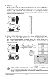
... Please connect the L-shaped end of the SATA 3Gb/s cable to be used, the total number of hard drives must be an even number. Hardware Installation - 24 - Refer to SATA 3Gb/s standard and are to your SATA hard drive. • A RAID 0 or RAID 1 configuration requires at least four hard drives and...
... Please connect the L-shaped end of the SATA 3Gb/s cable to be used, the total number of hard drives must be an even number. Hardware Installation - 24 - Refer to SATA 3Gb/s standard and are to your SATA hard drive. • A RAID 0 or RAID 1 configuration requires at least four hard drives and...


