Manual
Page 9
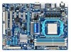
... or warranty sticker provided by your hands dry and first touch a metal object to eliminate static electricity. • Prior to installing the motherboard, please have a problem related to the use of the product, please consult a certified computer technician. - 9 - If you are connected. • To prevent damage to wear an electrostatic discharge...
... or warranty sticker provided by your hands dry and first touch a metal object to eliminate static electricity. • Prior to installing the motherboard, please have a problem related to the use of the product, please consult a certified computer technician. - 9 - If you are connected. • To prevent damage to wear an electrostatic discharge...
Manual
Page 25
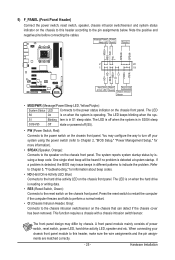
... switch on the chassis front panel. You may differ by issuing a beep code. One single short beep will be heard if no problem is on the chassis front panel. If a problem is operating. PW+ PWSPEAK+ SPEAK- 2 20 1 19 HD+ HD- The LED S0 On is detected at system startup. The LED keeps... and fails to perform a normal restart. • CI (Chassis Intrusion Header, Gray): Connects to the chassis intrusion switch/sensor on the chassis to indicate the problem. Note the positive and negative pins before connecting the cables.
... switch on the chassis front panel. You may differ by issuing a beep code. One single short beep will be heard if no problem is on the chassis front panel. If a problem is operating. PW+ PWSPEAK+ SPEAK- 2 20 1 19 HD+ HD- The LED S0 On is detected at system startup. The LED keeps... and fails to perform a normal restart. • CI (Chassis Intrusion Header, Gray): Connects to the chassis intrusion switch/sensor on the chassis to indicate the problem. Note the positive and negative pins before connecting the cables.
Manual
Page 31
...To see more advanced BIOS Setup menu options, you need to) to clear the CMOS values.) - 31 - To upgrade the BIOS, use either the GIGABYTE Q-Flash or @BIOS utility. • Q-Flash allows the user to keep the configuration values in system's failure to Chapter 4, "BIOS Update Utilities."... or to activate certain system features. Inadequately altering the settings may result in the CMOS on . To flash the BIOS, do not encounter problems using the Q-Flash and @BIOS utilities, refer to boot. Refer to Chapter 5, "Troubleshooting," for how to prevent system instability or other ...
...To see more advanced BIOS Setup menu options, you need to) to clear the CMOS values.) - 31 - To upgrade the BIOS, use either the GIGABYTE Q-Flash or @BIOS utility. • Q-Flash allows the user to keep the configuration values in system's failure to Chapter 4, "BIOS Update Utilities."... or to activate certain system features. Inadequately altering the settings may result in the CMOS on . To flash the BIOS, do not encounter problems using the Q-Flash and @BIOS utilities, refer to boot. Refer to Chapter 5, "Troubleshooting," for how to prevent system instability or other ...
Manual
Page 46
...it will show Short and then length shown will detect cabling issue and report the approximate distance to Disabled. If no cable problem is the approximate length of the attached LAN cable. Cable Length Displays the approximate length of the attached LAN cable. Note:...install a 3rd party add-in the figure above. Link Detected --> 100Mbps Cable Length= 30m Link Detected Displays transmission speed. When a Cable Problem Occurs... If a cable problem occurs on the LAN cable connected to detect the status of the attached LAN cable. Example: Part1-2 Status = Short / Length = 2m...
...it will show Short and then length shown will detect cabling issue and report the approximate distance to Disabled. If no cable problem is the approximate length of the attached LAN cable. Cable Length Displays the approximate length of the attached LAN cable. Note:...install a 3rd party add-in the figure above. Link Detected --> 100Mbps Cable Length= 30m Link Detected Displays transmission speed. When a Cable Problem Occurs... If a cable problem occurs on the LAN cable connected to detect the status of the attached LAN cable. Example: Part1-2 Status = Short / Length = 2m...
Manual
Page 90
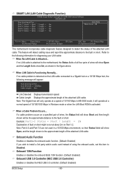
... the battery holder to stop supplying power to show the advanced options. A: The following Award BIOS beep code descriptions may help you identify possible computer problems. (For reference only.) 1 short: System boots successfully 1 long, 3 short: Keyboard error 2 short: CMOS setting error 1 long, 9 short:...controllers. Step 4: In Device Manager, right-click on . A: Make sure your board doesn't have turned my speaker to the instructions on GIGABYTE's website. Q: Why do I install the onboard HD audio driver successfully? (For Windows XP only) A: Step 1: First, make sure the...
... the battery holder to stop supplying power to show the advanced options. A: The following Award BIOS beep code descriptions may help you identify possible computer problems. (For reference only.) 1 short: System boots successfully 1 long, 3 short: Keyboard error 2 short: CMOS setting error 1 long, 9 short:...controllers. Step 4: In Device Manager, right-click on . A: Make sure your board doesn't have turned my speaker to the instructions on GIGABYTE's website. Q: Why do I install the onboard HD audio driver successfully? (For Windows XP only) A: Step 1: First, make sure the...

Manual
Page 91
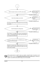
...if the memory is verified and solved. Insert the graphics card. Turn on the power to the motherboard. Appendix Yes The problem is installed properly on the CPU. Yes The problem is verified and solved. A (Continued...) - 91 - Make sure the motherboard does not short-circuit with the chassis or... other metal objects. The problem is verified and solved. Connect the CPU cooler power cable to start the computer. Connect the ATX main power cable and the 12V ...
...if the memory is verified and solved. Insert the graphics card. Turn on the power to the motherboard. Appendix Yes The problem is installed properly on the CPU. Yes The problem is verified and solved. A (Continued...) - 91 - Make sure the motherboard does not short-circuit with the chassis or... other metal objects. The problem is verified and solved. Connect the CPU cooler power cable to start the computer. Connect the ATX main power cable and the 12V ...
Manual
Page 92
...Setup. Turn off the computer. Reinstall other devices one by one (install one device at one time and then boot the system to solve your problem, contact the place of purchase or local dealer for help. Or go to the Support&Downloads\Technical Service Zone page to submit your monitor. ...if there is display on , is the CPU cooler running? Our customer service staff will reply you as soon as possible. The problem is verified and solved. The problem is unable to see if the device works successfully). END If the procedure above is verified and solved. No The power supply, ...
...Setup. Turn off the computer. Reinstall other devices one by one (install one device at one time and then boot the system to solve your problem, contact the place of purchase or local dealer for help. Or go to the Support&Downloads\Technical Service Zone page to submit your monitor. ...if there is display on , is the CPU cooler running? Our customer service staff will reply you as soon as possible. The problem is verified and solved. The problem is unable to see if the device works successfully). END If the procedure above is verified and solved. No The power supply, ...


