Manual
Page 3
...; 2009 GIGA-BYTE TECHNOLOGY CO., LTD. For example, "REV: 1.0" means the revision of the motherboard is the property of the product, read the Quick Installation Guide included with the product. Example: For instructions on how to their respective owners. For detailed product information, carefully read or download the information on/from the Support&Downloads\Motherboard\Technology Guide page on your motherboard revision before updating motherboard BIOS, drivers...
...; 2009 GIGA-BYTE TECHNOLOGY CO., LTD. For example, "REV: 1.0" means the revision of the motherboard is the property of the product, read the Quick Installation Guide included with the product. Example: For instructions on how to their respective owners. For detailed product information, carefully read or download the information on/from the Support&Downloads\Motherboard\Technology Guide page on your motherboard revision before updating motherboard BIOS, drivers...
Manual
Page 4
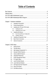
... Box Contents...6 Optional Items...6 GA-770T-USB3 Motherboard Layout 7 GA-770T-USB3 Motherboard Block Diagram 8 Chapter 1 Hardware Installation 9 1-1 Installation Precautions 9 1-2 Product Specifications 10 1-3 Installing the CPU and CPU Cooler 13 1-3-1 Installing the CPU 13 1-3-2 Installing the CPU Cooler 15 1-4 Installing the Memory 16 1-4-1 Dual Channel Memory Configuration 16 1-4-2 Installing a Memory 17 1-5 Installing an Expansion Card 18 1-6 Back Panel Connectors 19 1-7 Internal Connectors 21 Chapter 2 BIOS Setup 31 2-1 Startup Screen 32 2-2 The Main Menu 33 2-3 MB...
... Box Contents...6 Optional Items...6 GA-770T-USB3 Motherboard Layout 7 GA-770T-USB3 Motherboard Block Diagram 8 Chapter 1 Hardware Installation 9 1-1 Installation Precautions 9 1-2 Product Specifications 10 1-3 Installing the CPU and CPU Cooler 13 1-3-1 Installing the CPU 13 1-3-2 Installing the CPU Cooler 15 1-4 Installing the Memory 16 1-4-1 Dual Channel Memory Configuration 16 1-4-2 Installing a Memory 17 1-5 Installing an Expansion Card 18 1-6 Back Panel Connectors 19 1-7 Internal Connectors 21 Chapter 2 BIOS Setup 31 2-1 Startup Screen 32 2-2 The Main Menu 33 2-3 MB...

Manual
Page 10
...SATA2_4, SATA2_5) supporting up to 1 floppy disk drive USB South Bridge: - Up to 2 USB 3.0 ports on the back panel, 4 via the USB brackets connected to the internal USB headers) NEC D720200F1 chip - 1-2 Product Specifications CPU Support for AM3 processors: AMD Phenom™ II processor/ AMD Athlon™ II processor (Go to GIGABYTE's website for the latest CPU support list.) Hyper Transport Bus 5200 MT/s Chipset Memory Audio ...
...SATA2_4, SATA2_5) supporting up to 1 floppy disk drive USB South Bridge: - Up to 2 USB 3.0 ports on the back panel, 4 via the USB brackets connected to the internal USB headers) NEC D720200F1 chip - 1-2 Product Specifications CPU Support for AM3 processors: AMD Phenom™ II processor/ AMD Athlon™ II processor (Go to GIGABYTE's website for the latest CPU support list.) Hyper Transport Bus 5200 MT/s Chipset Memory Audio ...
Manual
Page 18
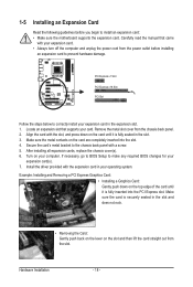
... BIOS changes for your expansion card. • Always turn off the computer and unplug the power cord from the chassis back panel. 2. After installing all expansion cards, replace the chassis cover(s). 6. Locate an expansion slot that came with a screw. 5. Make sure the card is fully seated in the expansion slot. 1. If necessary, go to BIOS Setup to the chassis back panel with your expansion card(s). 7. Hardware Installation - 18 - Carefully read the manual...
... BIOS changes for your expansion card. • Always turn off the computer and unplug the power cord from the chassis back panel. 2. After installing all expansion cards, replace the chassis cover(s). 6. Locate an expansion slot that came with a screw. 5. Make sure the card is fully seated in the expansion slot. 1. If necessary, go to BIOS Setup to the chassis back panel with your expansion card(s). 7. Hardware Installation - 18 - Carefully read the manual...
Manual
Page 30
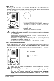
... power cord before turning on the two pins to temporarily short the two pins or use a metal object like a screwdriver to remove the jumper cap from the battery holder and wait for a few seconds. Hardware Installation - 30 - You may cause damage to the motherboard. • After system restart, go to BIOS Setup to load factory defaults (select Load Optimized Defaults) or manually configure the BIOS settings (refer to factory defaults. Plug in the CMOS...
... power cord before turning on the two pins to temporarily short the two pins or use a metal object like a screwdriver to remove the jumper cap from the battery holder and wait for a few seconds. Hardware Installation - 30 - You may cause damage to the motherboard. • After system restart, go to BIOS Setup to load factory defaults (select Load Optimized Defaults) or manually configure the BIOS settings (refer to factory defaults. Plug in the CMOS...
Manual
Page 32
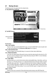
... Boot Menu, use the up hard drive data using the driver disk, the key can access Boot Menu again to change the first boot device setting as needed. : Q-FLASH Press the key to access the Q-Flash utility directly without entering BIOS Setup. BIOS Setup - 32 - 2-1 Startup Screen The following screens may appear when the computer boots. The system will still be used for GA-770T-USB3 E7 . . . . : BIOS Setup : XpressRecovery2 : Boot Menu : Qflash 12/14/2009-RX780-SB710-7A66AG0WC-00 Function Keys Function Keys: : POST SCREEN Press the key to show the BIOS POST screen...
... Boot Menu, use the up hard drive data using the driver disk, the key can access Boot Menu again to change the first boot device setting as needed. : Q-FLASH Press the key to access the Q-Flash utility directly without entering BIOS Setup. BIOS Setup - 32 - 2-1 Startup Screen The following screens may appear when the computer boots. The system will still be used for GA-770T-USB3 E7 . . . . : BIOS Setup : XpressRecovery2 : Boot Menu : Qflash 12/14/2009-RX780-SB710-7A66AG0WC-00 Function Keys Function Keys: : POST SCREEN Press the key to show the BIOS POST screen...
Manual
Page 34
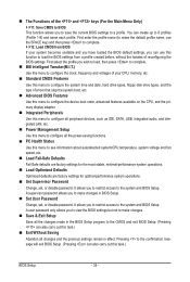
... default profile name, use this menu to load the BIOS settings from a profile created before, without the hassles of errors that stop the system boot, etc. Advanced BIOS Features Use this menu to configure the device boot order, advanced features available on the CPU, and the primary display adapter. Integrated Peripherals Use this menu to configure all peripheral devices, such as IDE, SATA, USB, integrated audio, and integrated LAN, etc. Power Management Setup Use this menu...
... default profile name, use this menu to load the BIOS settings from a profile created before, without the hassles of errors that stop the system boot, etc. Advanced BIOS Features Use this menu to configure the device boot order, advanced features available on the CPU, and the primary display adapter. Integrated Peripherals Use this menu to configure all peripheral devices, such as IDE, SATA, USB, integrated audio, and integrated LAN, etc. Power Management Setup Use this menu...
Manual
Page 43
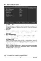
... as multiple virtual systems. (Default: Disabled) AMD K8 Cool&Quiet control Auto Lets the AMD Cool'n'Quiet driver dynamically adjust the CPU clock and VID to HDD Init Display First [Disabled] [Disabled] [Auto] [Press Enter] [Hard Disk] [CDROM] [Floppy] [Setup] [Disabled] [Disabled] [Enabled] [Disabled] [PCI Slot] Item Help Menu Level Move Enter: Select F5: Previous Values +/-/PU/PD: Value F10: Save F6: Fail-Safe Defaults ESC: Exit F1: General Help F7: Optimized Defaults AMD C1E Support (Note) Enables or disables the C1E CPU power-saving function...
... as multiple virtual systems. (Default: Disabled) AMD K8 Cool&Quiet control Auto Lets the AMD Cool'n'Quiet driver dynamically adjust the CPU clock and VID to HDD Init Display First [Disabled] [Disabled] [Auto] [Press Enter] [Hard Disk] [CDROM] [Floppy] [Setup] [Disabled] [Disabled] [Enabled] [Disabled] [PCI Slot] Item Help Menu Level Move Enter: Select F5: Previous Values +/-/PU/PD: Value F10: Save F6: Fail-Safe Defaults ESC: Exit F1: General Help F7: Optimized Defaults AMD C1E Support (Note) Enables or disables the C1E CPU power-saving function...
Manual
Page 44
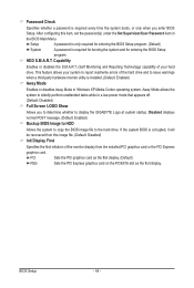
... hard drive and to issue warnings when a third party hardware monitor utility is required for booting the system and for entering the BIOS Setup program. (Default) System A password is installed. (Default: Enabled) Away Mode Enables or disables Away Mode in the BIOS Main Menu. Away Mode allows the system to silently perform unattended tasks while in a low-power mode that appears off. (Default: Disabled) Full Screen LOGO Show Allows you enter BIOS Setup. HDD S.M.A.R.T. PCI Sets the PCI graphics card as the first display. (Default) PEG Sets the PCI Express graphics card...
... hard drive and to issue warnings when a third party hardware monitor utility is required for booting the system and for entering the BIOS Setup program. (Default) System A password is installed. (Default: Enabled) Away Mode Enables or disables Away Mode in the BIOS Main Menu. Away Mode allows the system to silently perform unattended tasks while in a low-power mode that appears off. (Default: Disabled) Full Screen LOGO Show Allows you enter BIOS Setup. HDD S.M.A.R.T. PCI Sets the PCI graphics card as the first display. (Default) PEG Sets the PCI Express graphics card...
Manual
Page 45
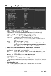
... CMOS Setup Utility-Copyright (C) 1984-2009 Award Software Integrated Peripherals OnChip SATA Controller OnChip SATA Type x OnChip SATA Port4/5 Type Onboard LAN Function Onboard LAN Boot ROM } SMART LAN Onboard Audio Function Onboard 1394 Function Onboard USB 3.0 Controller Onchip USB Controller USB EHCI Controllers USB Keyboard Support USB Mouse Support Legacy USB storage detect Onboard Serial Port 1 Onboard Parallel Port Parallel Port Mode x ECP Mode Use DMA [Enabled] [Native IDE] IDE [Enabled] [Disabled] [Press Enter] [Enabled] [Enabled...
... CMOS Setup Utility-Copyright (C) 1984-2009 Award Software Integrated Peripherals OnChip SATA Controller OnChip SATA Type x OnChip SATA Port4/5 Type Onboard LAN Function Onboard LAN Boot ROM } SMART LAN Onboard Audio Function Onboard 1394 Function Onboard USB 3.0 Controller Onchip USB Controller USB EHCI Controllers USB Keyboard Support USB Mouse Support Legacy USB storage detect Onboard Serial Port 1 Onboard Parallel Port Parallel Port Mode x ECP Mode Use DMA [Enabled] [Native IDE] IDE [Enabled] [Disabled] [Press Enter] [Enabled] [Enabled...
Manual
Page 46
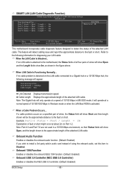
... motherboard incorporates cable diagnostic feature designed to Disabled. If a cable problem occurs on the LAN cable connected to the fault or short. Onboard 1394 Function Enables or disables the onboard IEEE 1394 function. (Default: Enabled) Onboard USB 3.0 Controller (NEC USB 3.0 Controller) Enables or disables the NEC USB 3.0 controller. (Default: Enabled) BIOS Setup - 46 - Cable Length Displays the approximate length of the attached LAN cable. Link Detected --> 100Mbps Cable Length= 30m Link Detected Displays transmission speed. Note: Part 4-5 and Part 7-8 are not used...
... motherboard incorporates cable diagnostic feature designed to Disabled. If a cable problem occurs on the LAN cable connected to the fault or short. Onboard 1394 Function Enables or disables the onboard IEEE 1394 function. (Default: Enabled) Onboard USB 3.0 Controller (NEC USB 3.0 Controller) Enables or disables the NEC USB 3.0 controller. (Default: Enabled) BIOS Setup - 46 - Cable Length Displays the approximate length of the attached LAN cable. Link Detected --> 100Mbps Cable Length= 30m Link Detected Displays transmission speed. Note: Part 4-5 and Part 7-8 are not used...
Manual
Page 47
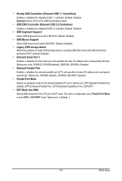
...Mode is set to be used in ECP mode. BIOS Setup Parallel Port Mode Selects an operating mode for the LPT port in MS-DOS. (Default: Disabled) Legacy USB storage detect Determines whether to detect USB storage devices, including USB flash drives and USB hard drives during the POST. (Default: Enabled) Onboard Serial Port 1 Enables or disables the first serial port and specifies its base I /O address and corresponding interrupt. Options are : SPP (Standard Parallel Port) (default), EPP (Enhanced Parallel Port), ECP (Extended Capabilities Port), ECP+EPP. USB EHCI Controller (Onboard USB...
...Mode is set to be used in ECP mode. BIOS Setup Parallel Port Mode Selects an operating mode for the LPT port in MS-DOS. (Default: Disabled) Legacy USB storage detect Determines whether to detect USB storage devices, including USB flash drives and USB hard drives during the POST. (Default: Enabled) Onboard Serial Port 1 Enables or disables the first serial port and specifies its base I /O address and corresponding interrupt. Options are : SPP (Standard Parallel Port) (default), EPP (Enhanced Parallel Port), ECP (Extended Capabilities Port), ECP+EPP. USB EHCI Controller (Onboard USB...
Manual
Page 48
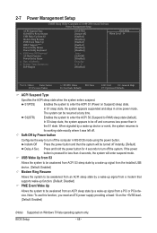
... +5VSB lead. (Default: Enabled) (Note) Supported on Suspend) sleep state. BIOS Setup - 48 - 2-7 Power Management Setup CMOS Setup Utility-Copyright (C) 1984-2009 Award Software Power Management Setup ACPI Suspend Type Soft-Off by Power button USB Wake Up from S3 Modem Ring Resume PME Event Wake Up HPET Support (Note) Power On By Mouse Power On By Keyboard x KB Power ON Password AC Back Function Power-On by a wake-up device or event, the system resumes to its working state exactly where...
... +5VSB lead. (Default: Enabled) (Note) Supported on Suspend) sleep state. BIOS Setup - 48 - 2-7 Power Management Setup CMOS Setup Utility-Copyright (C) 1984-2009 Award Software Power Management Setup ACPI Suspend Type Soft-Off by Power button USB Wake Up from S3 Modem Ring Resume PME Event Wake Up HPET Support (Note) Power On By Mouse Power On By Keyboard x KB Power ON Password AC Back Function Power-On by a wake-up device or event, the system resumes to its working state exactly where...
Manual
Page 51
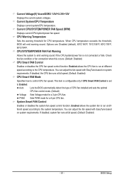
... CPU fan control mode. (Default) Voltage Sets Voltage mode for a 4-pin CPU fan. PWM Sets PWM mode for a 3-pin CPU fan. System Smart FAN Control Enables or disables the system fan speed control function. Current Voltage(V) Vcore/DDR3 1.5V/+3.3V/+12V Displays the current system voltages. CPU Warning Temperature Sets the warning threshold for CPU temperature. Current CPU/SYSTEM/POWER FAN Speed (RPM) Displays current CPU/system/power fan speed. If disabled, system fan runs at full speed. (Default: Enabled) CPU Smart FAN Mode Specifies how to the CPU temperature. BIOS Setup...
... CPU fan control mode. (Default) Voltage Sets Voltage mode for a 4-pin CPU fan. PWM Sets PWM mode for a 3-pin CPU fan. System Smart FAN Control Enables or disables the system fan speed control function. Current Voltage(V) Vcore/DDR3 1.5V/+3.3V/+12V Displays the current system voltages. CPU Warning Temperature Sets the warning threshold for CPU temperature. Current CPU/SYSTEM/POWER FAN Speed (RPM) Displays current CPU/system/power fan speed. If disabled, system fan runs at full speed. (Default: Enabled) CPU Smart FAN Mode Specifies how to the CPU temperature. BIOS Setup...
Manual
Page 62
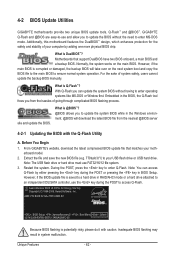
... BIOS while in RAID/AHCI mode or a hard drive attached to access Q-Flash. From GIGABYTE's website, download the latest compressed BIOS update file that support DualBIOS have two BIOS onboard, a main BIOS and a backup BIOS. site and update the BIOS. Before You Begin 1. Additionally, this motherboard features the DualBIOS™ design, which enhances protection for GA-770T-USB3 E7 . . . . : BIOS Setup : XpressRecovery2 : Boot Menu : Qflash 12/14/2009-RX780-SB710-7A66AG0WC-00 Because BIOS flashing is saved to a hard drive in the Windows environment. @BIOS...
... BIOS while in RAID/AHCI mode or a hard drive attached to access Q-Flash. From GIGABYTE's website, download the latest compressed BIOS update file that support DualBIOS have two BIOS onboard, a main BIOS and a backup BIOS. site and update the BIOS. Before You Begin 1. Additionally, this motherboard features the DualBIOS™ design, which enhances protection for GA-770T-USB3 E7 . . . . : BIOS Setup : XpressRecovery2 : Boot Menu : Qflash 12/14/2009-RX780-SB710-7A66AG0WC-00 Because BIOS flashing is saved to a hard drive in the Windows environment. @BIOS...
Manual
Page 63
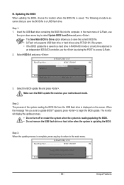
... sure the BIOS update file matches your motherboard model. Step 2: The process of Q-Flash, use the up or down arrow key to select Update BIOS from Drive Save BIOS to a USB flash drive. Q-Flash Utility v2.13 Flash Type/Size MXIC 25L8005 1M Keep0 DfilMe(Is)DfaotuandEnable HDD 0-0 Loa d CMO S Default Enable Update BIOS from Drive and press . • The Save Main BIOS to Drive option allows you to save the BIOS file to Drive Enter : Run hi:Move Total size : 0 ESC:Reset Free size : 0 F10:Power Off 3. Select HDD 0-0 and...
... sure the BIOS update file matches your motherboard model. Step 2: The process of Q-Flash, use the up or down arrow key to select Update BIOS from Drive Save BIOS to a USB flash drive. Q-Flash Utility v2.13 Flash Type/Size MXIC 25L8005 1M Keep0 DfilMe(Is)DfaotuandEnable HDD 0-0 Loa d CMO S Default Enable Update BIOS from Drive and press . • The Save Main BIOS to Drive option allows you to save the BIOS file to Drive Enter : Run hi:Move Total size : 0 ESC:Reset Free size : 0 F10:Power Off 3. Select HDD 0-0 and...
Manual
Page 66
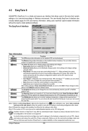
... file). (Note 1) Before enabling Easy Boost, right-click the EasyTune 6 icon in Easy mode/Advanced mode, be enabled/disabled depends on a specific slot to the hardware components such as CPU, chipset, and memory and reduce the useful life of EasyTune 6, or system instability or other unexpected results may differ by motherboard model. The Graphics tab allows you to take effect or click Default to restore to install...
... file). (Note 1) Before enabling Easy Boost, right-click the EasyTune 6 icon in Easy mode/Advanced mode, be enabled/disabled depends on a specific slot to the hardware components such as CPU, chipset, and memory and reduce the useful life of EasyTune 6, or system instability or other unexpected results may differ by motherboard model. The Graphics tab allows you to take effect or click Default to restore to install...
Manual
Page 77
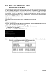
... /are configured to RAID/AHCI mode, you also can copy the SATA controller driver from the motherboard driver disk to a floppy disk. Appendix Steps: 1: Boot from the motherboard driver disk to a USB flash drive. First of all, copy the driver for the SATA controller from the startup disk. 2: Remove the startup disk and insert the prepared floppy disk and the motherboard driver disk (here we as- Refer to be recognized during the OS installation. Press after the command: For the AMD SB710, type...
... /are configured to RAID/AHCI mode, you also can copy the SATA controller driver from the motherboard driver disk to a floppy disk. Appendix Steps: 1: Boot from the motherboard driver disk to a USB flash drive. First of all, copy the driver for the SATA controller from the startup disk. 2: Remove the startup disk and insert the prepared floppy disk and the motherboard driver disk (here we as- Refer to be recognized during the OS installation. Press after the command: For the AMD SB710, type...
Manual
Page 79
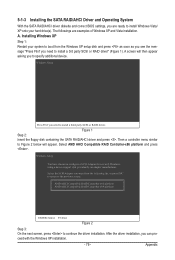
... installation. Select AMD AHCI Compatible RAID Controller-x86 platform and press . Figure 1 Step 2: Insert the floppy disk containing the SATA RAID/AHCI driver and press . Appendix Installing Windows XP Step 1: Restart your hard drive(s). Then a controller menu similar to Figure 2 below will then appear asking you need to install a third party SCSI or RAID driver. A screen will appear. 5-1-3 Installing the SATA RAID/AHCI Driver and Operating System With the SATA RAID/AHCI driver diskette and correct BIOS settings, you want from the Windows XP setup disk...
... installation. Select AMD AHCI Compatible RAID Controller-x86 platform and press . Figure 1 Step 2: Insert the floppy disk containing the SATA RAID/AHCI driver and press . Appendix Installing Windows XP Step 1: Restart your hard drive(s). Then a controller menu similar to Figure 2 below will then appear asking you need to install a third party SCSI or RAID driver. A screen will appear. 5-1-3 Installing the SATA RAID/AHCI Driver and Operating System With the SATA RAID/AHCI driver diskette and correct BIOS settings, you want from the Windows XP setup disk...
Manual
Page 90
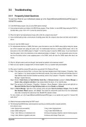
...install the onboard HD audio driver successfully? (For Windows XP only) A: Step 1: First, make sure the Microsoft UAA Bus Driver for hardware changes. Q: Why cannot I clear the CMOS values? A: The following Award BIOS beep code descriptions may help you identify possible computer problems. (For reference only.) 1 short: System boots successfully 1 long, 3 short: Keyboard error 2 short: CMOS setting error 1 long, 9 short: BIOS ROM error 1 long, 1 short: Memory or motherboard error Continuous long beeps: Graphics card not inserted properly 1 long, 2 short: Monitor or graphics card...
...install the onboard HD audio driver successfully? (For Windows XP only) A: Step 1: First, make sure the Microsoft UAA Bus Driver for hardware changes. Q: Why cannot I clear the CMOS values? A: The following Award BIOS beep code descriptions may help you identify possible computer problems. (For reference only.) 1 short: System boots successfully 1 long, 3 short: Keyboard error 2 short: CMOS setting error 1 long, 9 short: BIOS ROM error 1 long, 1 short: Memory or motherboard error Continuous long beeps: Graphics card not inserted properly 1 long, 2 short: Monitor or graphics card...


