Manual
Page 1
GA-6UASL series LGA1155 socket motherboard for Intel® Core™ i3 processors/ Intel® E3® series processors User's Manual Rev. 1001
GA-6UASL series LGA1155 socket motherboard for Intel® Core™ i3 processors/ Intel® E3® series processors User's Manual Rev. 1001
Manual
Page 3
Table of Contents Box Contents...4 GA-6UASL1 Motherboard Layout 5 Chapter 1 Hardware Installation 7 1-1 Installation Precautions 7 1-2 Product Specifications 8 1-3-2 Installing the CPU Cooler 11 1-4 Installing the Memory 12 1-4-1 Dual Channel Memory Configuration 12 1-4-2 Installing a Memory 13 1-5 ...
Table of Contents Box Contents...4 GA-6UASL1 Motherboard Layout 5 Chapter 1 Hardware Installation 7 1-1 Installation Precautions 7 1-2 Product Specifications 8 1-3-2 Installing the CPU Cooler 11 1-4 Installing the Memory 12 1-4-1 Dual Channel Memory Configuration 12 1-4-2 Installing a Memory 13 1-5 ...
Manual
Page 4
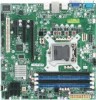
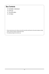
Box Contents GA-6UASL1 motherboard Driver CD Two SATA cables I/O Shield • The box contents above are subject to change without notice. • The motherboard image is for reference only and the actual items shall depend on the product package you obtain. The box contents are for reference only. - 4 -
Box Contents GA-6UASL1 motherboard Driver CD Two SATA cables I/O Shield • The box contents above are subject to change without notice. • The motherboard image is for reference only and the actual items shall depend on the product package you obtain. The box contents are for reference only. - 4 -
Manual
Page 5
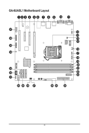
GA-6UASL1 Motherboard Layout - 5 -
GA-6UASL1 Motherboard Layout - 5 -
Manual
Page 7
...to wear an electrostatic discharge (ESD) wrist strap when handling electronic com- Chapter 1 Hardware Installation 1-1 Installation Precautions The motherboard contains numerous delicate electronic circuits and components which can lead to damage to system components as well as a result of ...all cables and power connectors of the product, please consult a certified computer technician. - 7 - Hardware Installation ponents such as a motherboard, CPU or memory. Prior to installation, carefully read the user's manual and follow these procedures: • Prior to installation, do...
...to wear an electrostatic discharge (ESD) wrist strap when handling electronic com- Chapter 1 Hardware Installation 1-1 Installation Precautions The motherboard contains numerous delicate electronic circuits and components which can lead to damage to system components as well as a result of ...all cables and power connectors of the product, please consult a certified computer technician. - 7 - Hardware Installation ponents such as a motherboard, CPU or memory. Prior to installation, carefully read the user's manual and follow these procedures: • Prior to installation, do...
Manual
Page 10
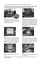
... the load plate, make sure to the CPU. Step 2: Remove the CPU socket cover as well. Step 5: Push the CPU socket lever back into the motherboard CPU socket. Follow the steps below to lightly replace the load plate. B. Align the CPU pin one marking (triangle) with your thumb to lift up...
... the load plate, make sure to the CPU. Step 2: Remove the CPU socket cover as well. Step 5: Push the CPU socket lever back into the motherboard CPU socket. Follow the steps below to lightly replace the load plate. B. Align the CPU pin one marking (triangle) with your thumb to lift up...
Manual
Page 11
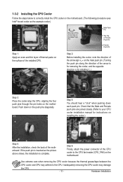
... may adhere to the CPU. Hardware Installation 1-3-2 Installing the CPU Cooler Follow the steps below to correctly install the CPU cooler on the motherboard. (The following procedure uses Intel® boxed cooler as the picture above shows, the installation is complete. Push down each push pin.... Step 4: You should hear a "click" when pushing down on the motherboard. Step 6: Finally, attach the power connector of the CPU cooler to your CPU cooler installation manual for installing it..) Step 3: Place the ...
... may adhere to the CPU. Hardware Installation 1-3-2 Installing the CPU Cooler Follow the steps below to correctly install the CPU cooler on the motherboard. (The following procedure uses Intel® boxed cooler as the picture above shows, the installation is complete. Push down each push pin.... Step 4: You should hear a "click" when pushing down on the motherboard. Step 6: Finally, attach the power connector of the CPU cooler to your CPU cooler installation manual for installing it..) Step 3: Place the ...

Manual
Page 12
... you begin to insert the memory, switch the direction. 1-4-1 Dual Channel Memory Configuration This motherboard provides four DDR3 memory sockets and supports Dual Channel Technology. Hardware Installation - 12 - It...only one direction. The four DDR3 memory sockets are unable to install the memory: • Make sure that the motherboard supports the memory. 1-4 Installing the Memory Read the following guidelines before you are divided into two channels and each ... capacity of the same capacity, brand, speed, and chips be used . (Go to GIGABYTE's website for optimum performance.
... you begin to insert the memory, switch the direction. 1-4-1 Dual Channel Memory Configuration This motherboard provides four DDR3 memory sockets and supports Dual Channel Technology. Hardware Installation - 12 - It...only one direction. The four DDR3 memory sockets are unable to install the memory: • Make sure that the motherboard supports the memory. 1-4 Installing the Memory Read the following guidelines before you are divided into two channels and each ... capacity of the same capacity, brand, speed, and chips be used . (Go to GIGABYTE's website for optimum performance.
Manual
Page 13
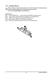
... Installation For dual-channel operation, DIMMs must be installed in order starting from the power outlet to prevent damage to install DDR3 DIMMs on this motherboard. Reverse the installation steps when you wish to lock the DIMM module. Be sure to the memory module. Step 3. 1-4-2 Installing a Memory Before installing a memory module...
... Installation For dual-channel operation, DIMMs must be installed in order starting from the power outlet to prevent damage to install DDR3 DIMMs on this motherboard. Reverse the installation steps when you wish to lock the DIMM module. Be sure to the memory module. Step 3. 1-4-2 Installing a Memory Before installing a memory module...

Manual
Page 15
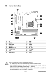
... is occurring • When removing the cable connected to a back panel connector, first remove the cable from your device and then remove it from the motherboard. • When removing the cable, pull it side to side to prevent an electrical short inside the cable connector.
... is occurring • When removing the cable connected to a back panel connector, first remove the cable from your device and then remove it from the motherboard. • When removing the cable, pull it side to side to prevent an electrical short inside the cable connector.
Manual
Page 16
..., make sure your devices are compliant with the connectors you wish to connect. • Before installing the devices, be sure to the connector on the motherboard. - 16 -
..., make sure your devices are compliant with the connectors you wish to connect. • Before installing the devices, be sure to the connector on the motherboard. - 16 -
Manual
Page 17
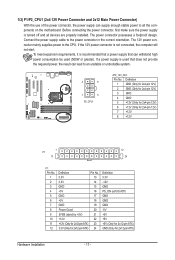
... mainly supplies power to the power connector in the correct orientation. If the 12V power connector is turned off and all the components on the motherboard. The power connector possesses a foolproof design. Before connecting the power connector, first make sure the power supply is not connected, the computer will not start...
... mainly supplies power to the power connector in the correct orientation. If the 12V power connector is turned off and all the components on the motherboard. The power connector possesses a foolproof design. Before connecting the power connector, first make sure the power supply is not connected, the computer will not start...
Manual
Page 19
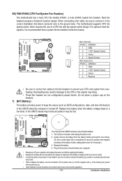
... GND 2 +12V / Speed Control 3 Sense 4 Speed Control FAN4 (System Fan): Pin No. Turn off . 5/6) FAN1/FAN4 (CPU Fan/System Fan Headers) The motherboard has a 4-pin CPU fan header (FAN1), a 4-pin (FAN4) system fan headers. Plug in damage to a low level, or the CMOS values may not be ...not place a jumper cap on the headers. 7) BAT (Battery) The battery provides power to replace the battery by removing the battery: 1. The motherboard supports CPU fan speed control, which requires the use a metal object like a screwdriver to touch the positive and negative terminals of the battery (the...
... GND 2 +12V / Speed Control 3 Sense 4 Speed Control FAN4 (System Fan): Pin No. Turn off . 5/6) FAN1/FAN4 (CPU Fan/System Fan Headers) The motherboard has a 4-pin CPU fan header (FAN1), a 4-pin (FAN4) system fan headers. Plug in damage to a low level, or the CMOS values may not be ...not place a jumper cap on the headers. 7) BAT (Battery) The battery provides power to replace the battery by removing the battery: 1. The motherboard supports CPU fan speed control, which requires the use a metal object like a screwdriver to touch the positive and negative terminals of the battery (the...
Manual
Page 28
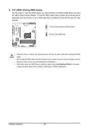
... values to clear the CMOS values (e.g. 5) CLR_CMOS1 (Clearing CMOS Jumper) Use this jumper to factory defaults. Failure to do so may cause damage to the motherboard. • After system restart, go to BIOS Setup to load factory defaults (select Load Optimized Defaults) or manually configure the BIOS settings (refer to Chapter...
... values to clear the CMOS values (e.g. 5) CLR_CMOS1 (Clearing CMOS Jumper) Use this jumper to factory defaults. Failure to do so may cause damage to the motherboard. • After system restart, go to BIOS Setup to load factory defaults (select Load Optimized Defaults) or manually configure the BIOS settings (refer to Chapter...
Manual
Page 29
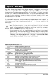
... include conducting the Power-On Self-Test (POST) during the POST when the power is recommended that you do it is turned on the motherboard. To flash the BIOS, do not encounter problems of using the current BIOS version, it with caution. Inadequately altering the settings may result ... introductions of the battery/ clearing CMOS jumper in the main menu of the function keys Move cursor to the Item Help block on the motherboard supplies the necessary power to the CMOS to keep the configuration values in the CMOS. BIOS includes a BIOS Setup program that you not ...
... include conducting the Power-On Self-Test (POST) during the POST when the power is recommended that you do it is turned on the motherboard. To flash the BIOS, do not encounter problems of using the current BIOS version, it with caution. Inadequately altering the settings may result ... introductions of the battery/ clearing CMOS jumper in the main menu of the function keys Move cursor to the Item Help block on the motherboard supplies the necessary power to the CMOS to keep the configuration values in the CMOS. BIOS includes a BIOS Setup program that you not ...
Manual
Page 1
GA-6FASV Series Xeon Processor Motherboard USER'S Manual Xeon® Processor Motherboard Rev. 1001 * The WEEE marking on the product indicates this product must not be disposed of with user's other household waste and must be handed over to a designated collection point for the recycling of waste electrical and electronic equipment!! * The WEEE marking applies only in European Union's member states.
GA-6FASV Series Xeon Processor Motherboard USER'S Manual Xeon® Processor Motherboard Rev. 1001 * The WEEE marking on the product indicates this product must not be disposed of with user's other household waste and must be handed over to a designated collection point for the recycling of waste electrical and electronic equipment!! * The WEEE marking applies only in European Union's member states.

Manual
Page 2
... Power ...49 Security ...51 Server ...53 System Management ...54 Console Redirection ...55 DMI Event Logging ...57 2 GA-6FASV Series Motherboard Table of Contents Item Checklist 4 Chapter 1Introduction 5 1.1.Considerations Prior to Installation 5 1.2.Features Summary 6 1.3.GA-6FASV1/GA-6FASV2 Motherboard Component 8 Chapter 2Hardware Installation Process 10 2.1.Installing Processor and CPU Heat Sink 10 2.1.1.Installing CPU ...10 2.1.2.Installing...
... Power ...49 Security ...51 Server ...53 System Management ...54 Console Redirection ...55 DMI Event Logging ...57 2 GA-6FASV Series Motherboard Table of Contents Item Checklist 4 Chapter 1Introduction 5 1.1.Considerations Prior to Installation 5 1.2.Features Summary 6 1.3.GA-6FASV1/GA-6FASV2 Motherboard Component 8 Chapter 2Hardware Installation Process 10 2.1.Installing Processor and CPU Heat Sink 10 2.1.1.Installing CPU ...10 2.1.2.Installing...

Manual
Page 3
GA-6FASV Series Motherboard Boot ...59 Exit ...60 3
GA-6FASV Series Motherboard Boot ...59 Exit ...60 3

Manual
Page 4
Item Checklist The GA-6FASV1 motherboard The GA-6FASV2 motherboard Serial ATA cable x 2 I/O Shield Kit CD for motherboard driver & utility The GA-6FASV1/The GA-6FASV2 quick reference guide GA-6FASV Series Motherboard * The items listed above are for reference only, and are subject to change without notice. 4
Item Checklist The GA-6FASV1 motherboard The GA-6FASV2 motherboard Serial ATA cable x 2 I/O Shield Kit CD for motherboard driver & utility The GA-6FASV1/The GA-6FASV2 quick reference guide GA-6FASV Series Motherboard * The items listed above are for reference only, and are subject to change without notice. 4
Manual
Page 5
... its power cord. 2. Considerations Prior to use exceeding the permitted parameters. 6. If you are required for warranty validation. 2. Damage due to be an unofficial Gigabyte product. 5 GA-6FASV Series Motherboard Chapter 1 Introduction 1.1. Installation Notices 1. Damage due to installation, please follow the instructions below: 1. These stickers are uncertain about any installation steps or have...
... its power cord. 2. Considerations Prior to use exceeding the permitted parameters. 6. If you are required for warranty validation. 2. Damage due to be an unofficial Gigabyte product. 5 GA-6FASV Series Motherboard Chapter 1 Introduction 1.1. Installation Notices 1. Damage due to installation, please follow the instructions below: 1. These stickers are uncertain about any installation steps or have...


