Manual
Page 1
GA-6KIEH-RH GA-6KIEH2-RH GA-6KIEL-RH Intel® mini-ITX Motherboard USER'S MANUAL Intel® mini-ITX Motherboard Rev. 1201 * The WEEE marking on the product indicates this product must not be disposed of with user's other household waste and must be handed over to a designated collection point for the recycling of waste electrical and electronic equipment!! * The WEEE marking applies only in European Union's member states.
GA-6KIEH-RH GA-6KIEH2-RH GA-6KIEL-RH Intel® mini-ITX Motherboard USER'S MANUAL Intel® mini-ITX Motherboard Rev. 1201 * The WEEE marking on the product indicates this product must not be disposed of with user's other household waste and must be handed over to a designated collection point for the recycling of waste electrical and electronic equipment!! * The WEEE marking applies only in European Union's member states.
Manual
Page 2
...GA-6KIEH-RH/GA-6KIEH2-RH/GA-6KIEL-RH Motherboard Copyright © 2007 GIGA-BYTE TECHNOLOGY CO., LTD. All rights reserved. Specifications and features are legally registered to read the "Product User Manual". For detailed information related to Gigabyte's unique features, please go to "Technology Guide" section on Gigabyte's website to their respective companies. No part of this product, Gigabyte... any means without prior notice. For more product details, please click onto Gigabyte's website at www.gigabyte.com.tw 2 Notice The written content provided with this product is the ...
...GA-6KIEH-RH/GA-6KIEH2-RH/GA-6KIEL-RH Motherboard Copyright © 2007 GIGA-BYTE TECHNOLOGY CO., LTD. All rights reserved. Specifications and features are legally registered to read the "Product User Manual". For detailed information related to Gigabyte's unique features, please go to "Technology Guide" section on Gigabyte's website to their respective companies. No part of this product, Gigabyte... any means without prior notice. For more product details, please click onto Gigabyte's website at www.gigabyte.com.tw 2 Notice The written content provided with this product is the ...

Manual
Page 3
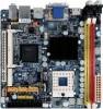
... 5 Chapter 1 Introduction 6 1-1 Considerations Prior to Installation 6 1.2 Features Summary 7 1.3 Motherboard Components (GA-6KIEH-RH 9 1.4 Motherboard Components (GA-6KIEL-RH 10 Chapter 2 Hardware Installation Process 11 2-1: Installing Processor 11 2-2: Installing Processor Colling Fan 12 2-3: Install... 13 2-4: Connect ribbon cables, cabinet wires, and power supply 15 2-4-1 : I/O Back Panel Introduction (GA-6KIEH-RH 15 2-4-2 : I/O Back Panel Introduction (GA-6KIEL-RH 16 2-5: Connectors Introduction & Jumper Setting 20 2-6: Block Diagram 27 Chapter 3 BIOS Setup 28 Main ......
... 5 Chapter 1 Introduction 6 1-1 Considerations Prior to Installation 6 1.2 Features Summary 7 1.3 Motherboard Components (GA-6KIEH-RH 9 1.4 Motherboard Components (GA-6KIEL-RH 10 Chapter 2 Hardware Installation Process 11 2-1: Installing Processor 11 2-2: Installing Processor Colling Fan 12 2-3: Install... 13 2-4: Connect ribbon cables, cabinet wires, and power supply 15 2-4-1 : I/O Back Panel Introduction (GA-6KIEH-RH 15 2-4-2 : I/O Back Panel Introduction (GA-6KIEL-RH 16 2-5: Connectors Introduction & Jumper Setting 20 2-6: Block Diagram 27 Chapter 3 BIOS Setup 28 Main ......
Manual
Page 4
GA-6KIEH-RH/GA-6KIEH2-RH/GA-6KIEL-RH Motherboard Security ...49 TPM State 51 Boot ...52 Exit ...53 4
GA-6KIEH-RH/GA-6KIEH2-RH/GA-6KIEL-RH Motherboard Security ...49 TPM State 51 Boot ...52 Exit ...53 4
Manual
Page 5
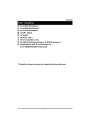
Item Checklist The GA-6KIEH-RH motherboard The GA-6KIEH2-RH motherboard The GA-6KIEL-RH motherboard Serial ATA cable x 2 I/O Shield Kit IDE (ATA100 ) cable x 1 CD for motherboard driver & utility GA--6KIEH-RH Quick Reference Guide (for GA-6KIEH-RH motherboard) GA-6KIEH2-RH/GA--6KIEL-RL Quick Reference Guide (for GA-6KIEH2-RH/GA-6KIEL-RH motherboard) Introduction * The items listed above are for reference only, and are subject to change without notice. 5
Item Checklist The GA-6KIEH-RH motherboard The GA-6KIEH2-RH motherboard The GA-6KIEL-RH motherboard Serial ATA cable x 2 I/O Shield Kit IDE (ATA100 ) cable x 1 CD for motherboard driver & utility GA--6KIEH-RH Quick Reference Guide (for GA-6KIEH-RH motherboard) GA-6KIEH2-RH/GA--6KIEL-RL Quick Reference Guide (for GA-6KIEH2-RH/GA-6KIEL-RH motherboard) Introduction * The items listed above are for reference only, and are subject to change without notice. 5
Manual
Page 6
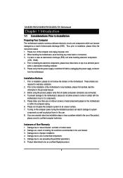
... or metal components placed on the motherboard or within a electrostatic shielding container. 5. Prior to be an unofficial Gigabyte product. 6 Please turn off before unplugging the power supply connector from the motherboard. Installation Notices 1. GA-6KIEH-RH/GA-6KIEH2-RH/GA-6KIEL-RH Motherboard Chapter 1 Introduction 1-1 Considerations Prior to Installation Preparing Your Computer The motherboard contains numerous delicate electronic circuits...
... or metal components placed on the motherboard or within a electrostatic shielding container. 5. Prior to be an unofficial Gigabyte product. 6 Please turn off before unplugging the power supply connector from the motherboard. Installation Notices 1. GA-6KIEH-RH/GA-6KIEH2-RH/GA-6KIEL-RH Motherboard Chapter 1 Introduction 1-1 Considerations Prior to Installation Preparing Your Computer The motherboard contains numerous delicate electronic circuits...
Manual
Page 7
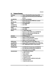
... single Intel® Merom/Penryn/Celeron M550 series (GA-6KIEH-RH) CPU (GA-6KIEL-RH) Chipset (GA-6KIEH-RH) processor y Socket P with 533/800MHz y Supports single Intel® Celeron M550 series processor y Socket P with 533MHz y Intel® GME965 MCH y Intel® ICH8M (GA-6KIEH2-RH) Chipset (GA-6KIEL-RH) Memory I/O Control Expansion Slots SATA Controller (GA-6KIEH-RH) SATA Controller y Intel® GLE960 MCH y Intel®...
... single Intel® Merom/Penryn/Celeron M550 series (GA-6KIEH-RH) CPU (GA-6KIEL-RH) Chipset (GA-6KIEH-RH) processor y Socket P with 533/800MHz y Supports single Intel® Celeron M550 series processor y Socket P with 533MHz y Intel® GME965 MCH y Intel® ICH8M (GA-6KIEH2-RH) Chipset (GA-6KIEL-RH) Memory I/O Control Expansion Slots SATA Controller (GA-6KIEH-RH) SATA Controller y Intel® GLE960 MCH y Intel®...
Manual
Page 8
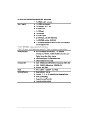
GA-6KIEH-RH/GA-6KIEH2-RH/GA-6KIEL-RH Motherboard y 1 x CPU fan cable connector Rear Panel I/O y 1 x SPDIF Out (Coaxial) y 1 x YPbPr prot (HDTV out ) y 1 x HDMI prot** y 1 x VGA port y 1 x DVI-D port** y 4 x USB 2.0 ports y 2 x LAN RJ45 ports (GA-6KIEH-RH) y 1 x LAN RJ45 port (GA-6KIEL-RH) y 1 HD Audio jacks (Line-out / MIC-...Detect y CPU shutdown when overheat On-Board LAN y Intel® 82566DC and 82573L GbE controllers (GA-6KIEH-RH) y Intel® 82566DC GbE controller (GA-6KIEL-RH) y Supports WOL, PXE BIOS y Phoenix BIOS on 8Mb SPI Flash ROM Additional Features y External...
GA-6KIEH-RH/GA-6KIEH2-RH/GA-6KIEL-RH Motherboard y 1 x CPU fan cable connector Rear Panel I/O y 1 x SPDIF Out (Coaxial) y 1 x YPbPr prot (HDTV out ) y 1 x HDMI prot** y 1 x VGA port y 1 x DVI-D port** y 4 x USB 2.0 ports y 2 x LAN RJ45 ports (GA-6KIEH-RH) y 1 x LAN RJ45 port (GA-6KIEL-RH) y 1 HD Audio jacks (Line-out / MIC-...Detect y CPU shutdown when overheat On-Board LAN y Intel® 82566DC and 82573L GbE controllers (GA-6KIEH-RH) y Intel® 82566DC GbE controller (GA-6KIEL-RH) y Supports WOL, PXE BIOS y Phoenix BIOS on 8Mb SPI Flash ROM Additional Features y External...
Manual
Page 12
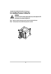
Secure the cooing fan with screws. To prevent the CPU overheat, please make sure you have apply the CPU cooler paste on the surface of installed CPU Step 1 Attach the heat sink n the procssor socket. GA-6KIEH-RH/GA-6KIEH2-RH/GA-6KIEL-RH Motherboard 2-2: Installing Processor Colling Fan WARNING! ! Step 2 Connect processor fan can cable to the processor fan connector. 1 1 1 2 12
Secure the cooing fan with screws. To prevent the CPU overheat, please make sure you have apply the CPU cooler paste on the surface of installed CPU Step 1 Attach the heat sink n the procssor socket. GA-6KIEH-RH/GA-6KIEH2-RH/GA-6KIEL-RH Motherboard 2-2: Installing Processor Colling Fan WARNING! ! Step 2 Connect processor fan can cable to the processor fan connector. 1 1 1 2 12
Manual
Page 14
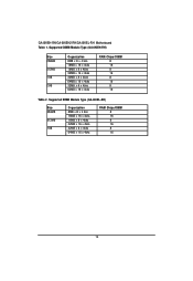
GA-6KIEH-RH/GA-6KIEH2-RH/GA-6KIEL-RH Motherboard Table 1. Supported DIMM Module Type (GA-6KIEH-RH) Size 256MB 512MB 1GB 2GB Organization 8MB x 8 x 4 bks 16MB x 16 x 4bks 16MB x 8 x 4bks 32MB x 16 x 4bks 32MB x 8 x 4bks 64MB x 16 x 4bks 32MB x 8 x 4bks 64MB x 16 x 4bks RAM Chips/DIMM 8 16 8 16 8 16 8 16 Table 2. Supported DIMM Module Type (GA-6KIEL-RH) Size 256MB 512MB 1GB Organization 8MB x 8 x 4 bks 16MB x 16 x 4bks 16MB x 8 x 4bks 32MB x 16 x 4bks 32MB x 8 x 4bks 64MB x 16 x 4bks RAM Chips/DIMM 8 16 8 16 8 16 14
GA-6KIEH-RH/GA-6KIEH2-RH/GA-6KIEL-RH Motherboard Table 1. Supported DIMM Module Type (GA-6KIEH-RH) Size 256MB 512MB 1GB 2GB Organization 8MB x 8 x 4 bks 16MB x 16 x 4bks 16MB x 8 x 4bks 32MB x 16 x 4bks 32MB x 8 x 4bks 64MB x 16 x 4bks 32MB x 8 x 4bks 64MB x 16 x 4bks RAM Chips/DIMM 8 16 8 16 8 16 8 16 Table 2. Supported DIMM Module Type (GA-6KIEL-RH) Size 256MB 512MB 1GB Organization 8MB x 8 x 4 bks 16MB x 16 x 4bks 16MB x 8 x 4bks 32MB x 16 x 4bks 32MB x 8 x 4bks 64MB x 16 x 4bks RAM Chips/DIMM 8 16 8 16 8 16 14
Manual
Page 15
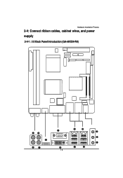
Hardware Installation Process 2-4: Connect ribbon cables, cabinet wires, and power supply 2-4-1 : I/O Back Panel Introduction (GA-6KIEH-RH) 15
Hardware Installation Process 2-4: Connect ribbon cables, cabinet wires, and power supply 2-4-1 : I/O Back Panel Introduction (GA-6KIEH-RH) 15
Manual
Page 16
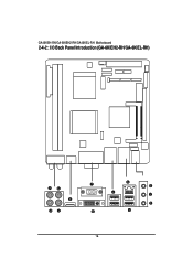
GA-6KIEH-RH/GA-6KIEH2-RH/GA-6KIEL-RH Motherboard 2-4-2 : I/O Back Panel Introduction (GA-6KIEH2-RH/GA-6KIEL-RH) 16
GA-6KIEH-RH/GA-6KIEH2-RH/GA-6KIEL-RH Motherboard 2-4-2 : I/O Back Panel Introduction (GA-6KIEH2-RH/GA-6KIEL-RH) 16
Manual
Page 18
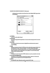
.... Stereo speakers, earphone or front surround speakers can be connected to this port. VGA Port Connect the monitor cable to MIC In jack. 18 GA-6KIEH-RH/GA-6KIEH2-RH/GA-6KIEL-RH Motherboard In Windows Vista, select Start>Control Panel>Sound, select Realtek HDMI Output and then click Set Default. Also make sure your OS supports USB...
.... Stereo speakers, earphone or front surround speakers can be connected to this port. VGA Port Connect the monitor cable to MIC In jack. 18 GA-6KIEH-RH/GA-6KIEH2-RH/GA-6KIEL-RH Motherboard In Windows Vista, select Start>Control Panel>Sound, select Realtek HDMI Output and then click Set Default. Also make sure your OS supports USB...
Manual
Page 20
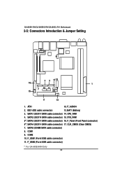
... 4. ATX1 12. IDE1 (IDE cable connector) 13. SYS_FAN1 5**. SATA3 (SiI3114 SATA cable connector) 16. F_Panel (Front Panel connector) 6**. F_USB2 (Fornt USB cable connector) ** For GA-6KIEH-RH Only 20 GA-6KIEH-RH/GA-6KIEH2-RH/GA-6KIEL-RH Motherboard 2-5: Connectors Introduction & Jumper Setting 8 12 9 4 3 17 13 16 1 15 7 10 11 5 6 2 14 1. BAT1 (Battery) 3. SATA5 (ICH8M SATA cable connector) 8. SATA2 (SiI3114 SATA...
... 4. ATX1 12. IDE1 (IDE cable connector) 13. SYS_FAN1 5**. SATA3 (SiI3114 SATA cable connector) 16. F_Panel (Front Panel connector) 6**. F_USB2 (Fornt USB cable connector) ** For GA-6KIEH-RH Only 20 GA-6KIEH-RH/GA-6KIEH2-RH/GA-6KIEL-RH Motherboard 2-5: Connectors Introduction & Jumper Setting 8 12 9 4 3 17 13 16 1 15 7 10 11 5 6 2 14 1. BAT1 (Battery) 3. SATA5 (ICH8M SATA cable connector) 8. SATA2 (SiI3114 SATA...
Manual
Page 22
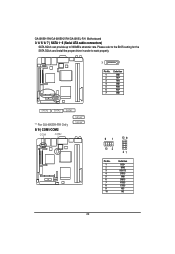
Please refer to the BIOS setting for the SATA 3Gb/s and install the proper driver in order to 300MB/s stransfer rate. GA-6KIEH-RH/GA-6KIEH2-RH/GA-6KIEL-RH Motherboard 3/ 4/ 5/ 6/ 7 ) SATA 1~5 (Serial ATA cable connectors) SATA 3Gb/s can provide up to work properly. 7 1 Pin No. 1 2 3 4 5 6 7 Definition GND TXP TXN GND RXN RXP GND SATA5 SATA2 SATA1 ** For GA-6KIEH-RH Only 8/ 9 ) COM1/COM2 COM1 COM2 SATA3** SATA4** 91 10 9 10 2 21 Pin No. 1 2 3 4 5 6 7 8 9 10 Definition DCDSIN2 SOUT2 DTR2GND DSR2RTS2CTS2RI2NC 22
Please refer to the BIOS setting for the SATA 3Gb/s and install the proper driver in order to 300MB/s stransfer rate. GA-6KIEH-RH/GA-6KIEH2-RH/GA-6KIEL-RH Motherboard 3/ 4/ 5/ 6/ 7 ) SATA 1~5 (Serial ATA cable connectors) SATA 3Gb/s can provide up to work properly. 7 1 Pin No. 1 2 3 4 5 6 7 Definition GND TXP TXN GND RXN RXP GND SATA5 SATA2 SATA1 ** For GA-6KIEH-RH Only 8/ 9 ) COM1/COM2 COM1 COM2 SATA3** SATA4** 91 10 9 10 2 21 Pin No. 1 2 3 4 5 6 7 8 9 10 Definition DCDSIN2 SOUT2 DTR2GND DSR2RTS2CTS2RI2NC 22
Manual
Page 24
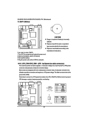
... power connector wire indicates a positive connection and requires a +12V power voltage. If you want to prevent CPU damage or system hanging caused by the manufacturer. GA-6KIEH-RH/GA-6KIEH2-RH/GA-6KIEL-RH Motherboard 13 ) BAT1 (Battery) CAUTION Danger of used batteries according to the manufacturer's instructions. Dispose of explosion if battery is the ground wire (GND...
... power connector wire indicates a positive connection and requires a +12V power voltage. If you want to prevent CPU damage or system hanging caused by the manufacturer. GA-6KIEH-RH/GA-6KIEH2-RH/GA-6KIEL-RH Motherboard 13 ) BAT1 (Battery) CAUTION Danger of used batteries according to the manufacturer's instructions. Dispose of explosion if battery is the ground wire (GND...
Manual
Page 26
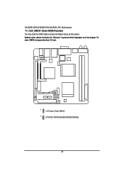
Default value doesn't include the "Shunter" to restore its default values by this jumper. To clear CMOS, temporarily short 2-3 pin. 1 1-2 Close: Clear CMOS 1 2-3 Close: Normal operation(Default setting) 26 GA-6KIEH-RH/GA-6KIEH2-RH/GA-6KIEL-RH Motherboard 17 ) CLR_CMOS1 (Clear CMOS Function) You may clear the CMOS data to prevent from improper use this jumper.
Default value doesn't include the "Shunter" to restore its default values by this jumper. To clear CMOS, temporarily short 2-3 pin. 1 1-2 Close: Clear CMOS 1 2-3 Close: Normal operation(Default setting) 26 GA-6KIEH-RH/GA-6KIEH2-RH/GA-6KIEL-RH Motherboard 17 ) CLR_CMOS1 (Clear CMOS Function) You may clear the CMOS data to prevent from improper use this jumper.

Manual
Page 28
... Page Setup Menu - Exit current page and return to activate certain system features. The CMOS SETUP saves the configuration in the right hand Main Menu - GA-6KIEH-RH/GA-6KIEL-RH Motherboard Chapter 3 BIOS Setup BIOS (Basic Input and Output System) includes a CMOS SETUP utility which allows user to configure required settings or to Main...
... Page Setup Menu - Exit current page and return to activate certain system features. The CMOS SETUP saves the configuration in the right hand Main Menu - GA-6KIEH-RH/GA-6KIEL-RH Motherboard Chapter 3 BIOS Setup BIOS (Basic Input and Output System) includes a CMOS SETUP utility which allows user to configure required settings or to Main...

Manual
Page 30
GA-6KIEH-RH/GA-6KIEL-RH Motherboard Main Once you set the date. (Weekend: DD: MM: YY) (YY: 1099~2099) 30 Use arrow keys to select among the items and press to accept or enter the sub-menu. Note that the "Day" automatically changed after you enter Phoenix BIOS Setup Utility, the Main Menu (Figure 1) will appear on the 24-hour military time clock. Set the System Time (HH:MM:SS) System Time Set the System Date. Figure 1: Main System Time The time is calculated based on the screen.
GA-6KIEH-RH/GA-6KIEL-RH Motherboard Main Once you set the date. (Weekend: DD: MM: YY) (YY: 1099~2099) 30 Use arrow keys to select among the items and press to accept or enter the sub-menu. Note that the "Day" automatically changed after you enter Phoenix BIOS Setup Utility, the Main Menu (Figure 1) will appear on the 24-hour military time clock. Set the System Time (HH:MM:SS) System Time Set the System Date. Figure 1: Main System Time The time is calculated based on the screen.
Manual
Page 32
... Errors Whenever the BIOS detects a non-fatal error the system will be prompted. No Errors The system boot will not stop for a keyboard error; GA-6KIEH-RH/GA-6KIEL-RH Motherboard installed Halt On The category determines whether the computer will stop if an error is detected during the POST. All, But Keyboard The system...
... Errors Whenever the BIOS detects a non-fatal error the system will be prompted. No Errors The system boot will not stop for a keyboard error; GA-6KIEH-RH/GA-6KIEL-RH Motherboard installed Halt On The category determines whether the computer will stop if an error is detected during the POST. All, But Keyboard The system...


