
Manual
Page 3
... 1.2 Features Summary 7 1.3 Motherboard Components (GA-6KIEH-RH 9 1.4 Motherboard Components (GA-6KIEL-RH 10 Chapter 2 Hardware Installation Process 11 2-1: Installing Processor 11 2-2: Installing Processor Colling Fan 12 2-3: Install Memory Modules 13 2-4: Connect ribbon cables, cabinet wires, and power supply 15 2-4-1 : I/O Back Panel Introduction (GA-6KIEH-RH 15 2-4-2 : I/O Back Panel Introduction (GA-6KIEL-RH 16 2-5: Connectors Introduction & Jumper Setting 20 2-6: Block Diagram 27 Chapter 3 BIOS Setup 28 Main ...30 Advanced 33 System Information ...34 CPU Feature ...35 GM965...
... 1.2 Features Summary 7 1.3 Motherboard Components (GA-6KIEH-RH 9 1.4 Motherboard Components (GA-6KIEL-RH 10 Chapter 2 Hardware Installation Process 11 2-1: Installing Processor 11 2-2: Installing Processor Colling Fan 12 2-3: Install Memory Modules 13 2-4: Connect ribbon cables, cabinet wires, and power supply 15 2-4-1 : I/O Back Panel Introduction (GA-6KIEH-RH 15 2-4-2 : I/O Back Panel Introduction (GA-6KIEL-RH 16 2-5: Connectors Introduction & Jumper Setting 20 2-6: Block Diagram 27 Chapter 3 BIOS Setup 28 Main ...30 Advanced 33 System Information ...34 CPU Feature ...35 GM965...
Manual
Page 5
Item Checklist The GA-6KIEH-RH motherboard The GA-6KIEH2-RH motherboard The GA-6KIEL-RH motherboard Serial ATA cable x 2 I/O Shield Kit IDE (ATA100 ) cable x 1 CD for motherboard driver & utility GA--6KIEH-RH Quick Reference Guide (for GA-6KIEH-RH motherboard) GA-6KIEH2-RH/GA--6KIEL-RL Quick Reference Guide (for GA-6KIEH2-RH/GA-6KIEL-RH motherboard) Introduction * The items listed above are for reference only, and are subject to change without notice. 5
Item Checklist The GA-6KIEH-RH motherboard The GA-6KIEH2-RH motherboard The GA-6KIEL-RH motherboard Serial ATA cable x 2 I/O Shield Kit IDE (ATA100 ) cable x 1 CD for motherboard driver & utility GA--6KIEH-RH Quick Reference Guide (for GA-6KIEH-RH motherboard) GA-6KIEH2-RH/GA--6KIEL-RL Quick Reference Guide (for GA-6KIEH2-RH/GA-6KIEL-RH motherboard) Introduction * The items listed above are for reference only, and are subject to change without notice. 5
Manual
Page 6
... the information in the user manual. 3. Damage due to use exceeding the permitted parameters. 6. Thus, prior to be an unofficial Gigabyte product. 6 Please verify that all cables and power connectors are required for warranty validation. 2. Damage as a result of Non-Warranty 1. Installation Notices 1. GA-6KIEH-RH/GA-6KIEH2-RH/GA-6KIEL-RH Motherboard Chapter 1 Introduction 1-1 Considerations Prior to Installation Preparing Your Computer The motherboard contains numerous delicate electronic...
... the information in the user manual. 3. Damage due to use exceeding the permitted parameters. 6. Thus, prior to be an unofficial Gigabyte product. 6 Please verify that all cables and power connectors are required for warranty validation. 2. Damage as a result of Non-Warranty 1. Installation Notices 1. GA-6KIEH-RH/GA-6KIEH2-RH/GA-6KIEL-RH Motherboard Chapter 1 Introduction 1-1 Considerations Prior to Installation Preparing Your Computer The motherboard contains numerous delicate electronic...
Manual
Page 7
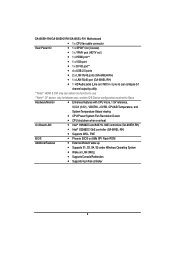
... 32-Bit/33MHz y Supports 1 mini card slot (PCI-E x1/ USB 2.0) y Supports 1 mini PCI slot (PCI 33Mhz) y Built in Silicon Image® SiI 3114 with RAID 0,1,10, 5 y Supports 5 SATA connectors (SiI3114 4 Ports, ICH8M 1 Port) y Intel ® ICH8M supports 3 SATA 3.0 Gb/s connectors (GA-6KIEL-RH) On-Board Graphic Internal Connector y Intel® GMA X3100 3D Graphic Engine (GA-6KIEH-RH) y Intel® GMA X3000 3D Graphic Engine (GA-6KIEL-RH) y Shared system memory up to 256MB y 1 x 20-pin ATX power connector y 5 x SATA connectors y 1 x IDE connector y 2 x Serial connectors (COM) y 1 x front audio...
... 32-Bit/33MHz y Supports 1 mini card slot (PCI-E x1/ USB 2.0) y Supports 1 mini PCI slot (PCI 33Mhz) y Built in Silicon Image® SiI 3114 with RAID 0,1,10, 5 y Supports 5 SATA connectors (SiI3114 4 Ports, ICH8M 1 Port) y Intel ® ICH8M supports 3 SATA 3.0 Gb/s connectors (GA-6KIEL-RH) On-Board Graphic Internal Connector y Intel® GMA X3100 3D Graphic Engine (GA-6KIEH-RH) y Intel® GMA X3000 3D Graphic Engine (GA-6KIEL-RH) y Shared system memory up to 256MB y 1 x 20-pin ATX power connector y 5 x SATA connectors y 1 x IDE connector y 2 x Serial connectors (COM) y 1 x front audio...
Manual
Page 8
GA-6KIEH-RH/GA-6KIEH2-RH/GA-6KIEL-RH Motherboard y 1 x CPU fan cable connector Rear Panel I/O y 1 x SPDIF Out (Coaxial) y 1 x YPbPr prot (HDTV out ) y 1 x HDMI prot** y 1 x VGA port y 1 x DVI-D port** y 4 x USB 2.0 ports y 2 x LAN RJ45 ports (GA-6KIEH-RH) y 1 x LAN RJ45 port (GA-6KIEL-RH) y 1 HD Audio jacks (Line-out / MIC-in / Line-in) can configure 5.1 channel output by utility **Note** HDMI & DVI only can select one function to use **Note** CF device only for Master user, and the IDE Device configuration must set to Slave Hardware Monitor y Enhanced features with CPU Vcore, ...
GA-6KIEH-RH/GA-6KIEH2-RH/GA-6KIEL-RH Motherboard y 1 x CPU fan cable connector Rear Panel I/O y 1 x SPDIF Out (Coaxial) y 1 x YPbPr prot (HDTV out ) y 1 x HDMI prot** y 1 x VGA port y 1 x DVI-D port** y 4 x USB 2.0 ports y 2 x LAN RJ45 ports (GA-6KIEH-RH) y 1 x LAN RJ45 port (GA-6KIEL-RH) y 1 HD Audio jacks (Line-out / MIC-in / Line-in) can configure 5.1 channel output by utility **Note** HDMI & DVI only can select one function to use **Note** CF device only for Master user, and the IDE Device configuration must set to Slave Hardware Monitor y Enhanced features with CPU Vcore, ...
Manual
Page 16
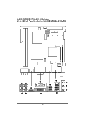
GA-6KIEH-RH/GA-6KIEH2-RH/GA-6KIEL-RH Motherboard 2-4-2 : I/O Back Panel Introduction (GA-6KIEH2-RH/GA-6KIEL-RH) 16
GA-6KIEH-RH/GA-6KIEH2-RH/GA-6KIEL-RH Motherboard 2-4-2 : I/O Back Panel Introduction (GA-6KIEH2-RH/GA-6KIEL-RH) 16
Manual
Page 17
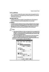
....) In Windows XP, select Start>Control Panel>Sounds and Audio Devices>Audio, set Onboard VGA output connect to Realtek HDA HDMI Out. 17 Connect the YPbPr cable to this port. Connect the HDMI audio/video device to these three ports. Blue port represents Pb port, Red represnts Pr port, and Green represent Y port. NOTE: After installing the HDMI device, make sure the default device for sound playback to D-SUB/ HDMI under Advanced BIOS Features. Please note the HDMI audio output only supports AC3, DTS and 2-channel-LPCM formats...
....) In Windows XP, select Start>Control Panel>Sounds and Audio Devices>Audio, set Onboard VGA output connect to Realtek HDA HDMI Out. 17 Connect the YPbPr cable to this port. Connect the HDMI audio/video device to these three ports. Blue port represents Pb port, Red represnts Pr port, and Green represent Y port. NOTE: After installing the HDMI device, make sure the default device for sound playback to D-SUB/ HDMI under Advanced BIOS Features. Please note the HDMI audio output only supports AC3, DTS and 2-channel-LPCM formats...
Manual
Page 18
... support USB controller, please contact OS vendor for possible patch or driver updated. Devices like CD-ROM, walkman etc. can be connected to Line Out (Front Speaker Out) jack. Microphone must be connected to MIC In jack. 18 Line Out (Front Speaker Out) The default Line Out (Front Speaker Out) jack. GA-6KIEH-RH/GA-6KIEH2-RH/GA-6KIEL-RH Motherboard In Windows Vista, select Start>Control Panel>Sound, select Realtek HDMI Output and then click Set Default. DVI-D Port...
... support USB controller, please contact OS vendor for possible patch or driver updated. Devices like CD-ROM, walkman etc. can be connected to Line Out (Front Speaker Out) jack. Microphone must be connected to MIC In jack. 18 Line Out (Front Speaker Out) The default Line Out (Front Speaker Out) jack. GA-6KIEH-RH/GA-6KIEH2-RH/GA-6KIEL-RH Motherboard In Windows Vista, select Start>Control Panel>Sound, select Realtek HDMI Output and then click Set Default. DVI-D Port...
Manual
Page 20
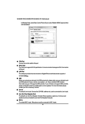
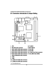
IDE1 (IDE cable connector) 13. SYS_FAN1 5**. COM1 9. SATA1 (SiI3114 SATA cable connector) 14. CLR_CMOS (Clear CMOS) 7. F_USB1 (Fornt USB cable connector) 11. F_AUDIO1 2. BAT1 (Battery) 3. SATA3 (SiI3114 SATA cable connector) 16. F_Panel (Front Panel connector) 6**. SATA2 (SiI3114 SATA cable connector) 15. COM2 10. ATX1 12. CPU_FAN1 4. F_USB2 (Fornt USB cable connector) ** For GA-6KIEH-RH Only 20 GA-6KIEH-RH/GA-6KIEH2-RH/GA-6KIEL-RH Motherboard 2-5: Connectors Introduction & Jumper Setting 8 12 9 4 3 17 13 16 1 15 7 10 11 5 6 2 14 1. SATA4 (...
IDE1 (IDE cable connector) 13. SYS_FAN1 5**. COM1 9. SATA1 (SiI3114 SATA cable connector) 14. CLR_CMOS (Clear CMOS) 7. F_USB1 (Fornt USB cable connector) 11. F_AUDIO1 2. BAT1 (Battery) 3. SATA3 (SiI3114 SATA cable connector) 16. F_Panel (Front Panel connector) 6**. SATA2 (SiI3114 SATA cable connector) 15. COM2 10. ATX1 12. CPU_FAN1 4. F_USB2 (Fornt USB cable connector) ** For GA-6KIEH-RH Only 20 GA-6KIEH-RH/GA-6KIEH2-RH/GA-6KIEL-RH Motherboard 2-5: Connectors Introduction & Jumper Setting 8 12 9 4 3 17 13 16 1 15 7 10 11 5 6 2 14 1. SATA4 (...
Manual
Page 22
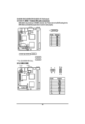
GA-6KIEH-RH/GA-6KIEH2-RH/GA-6KIEL-RH Motherboard 3/ 4/ 5/ 6/ 7 ) SATA 1~5 (Serial ATA cable connectors) SATA 3Gb/s can provide up to work properly. 7 1 Pin No. 1 2 3 4 5 6 7 Definition GND TXP TXN GND RXN RXP GND SATA5 SATA2 SATA1 ** For GA-6KIEH-RH Only 8/ 9 ) COM1/COM2 COM1 COM2 SATA3** SATA4** 91 10 9 10 2 21 Pin No. 1 2 3 4 5 6 7 8 9 10 Definition DCDSIN2 SOUT2 DTR2GND DSR2RTS2CTS2RI2NC 22 Please refer to the BIOS setting for the SATA 3Gb/s and install the proper driver in order to 300MB/s stransfer rate.
GA-6KIEH-RH/GA-6KIEH2-RH/GA-6KIEL-RH Motherboard 3/ 4/ 5/ 6/ 7 ) SATA 1~5 (Serial ATA cable connectors) SATA 3Gb/s can provide up to work properly. 7 1 Pin No. 1 2 3 4 5 6 7 Definition GND TXP TXN GND RXN RXP GND SATA5 SATA2 SATA1 ** For GA-6KIEH-RH Only 8/ 9 ) COM1/COM2 COM1 COM2 SATA3** SATA4** 91 10 9 10 2 21 Pin No. 1 2 3 4 5 6 7 8 9 10 Definition DCDSIN2 SOUT2 DTR2GND DSR2RTS2CTS2RI2NC 22 Please refer to the BIOS setting for the SATA 3Gb/s and install the proper driver in order to 300MB/s stransfer rate.
Manual
Page 24
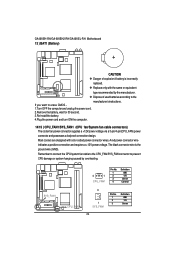
.... Replace only with color-coded power connector wires. A red power connector wire indicates a positive connection and requires a +12V power voltage. GA-6KIEH-RH/GA-6KIEH2-RH/GA-6KIEL-RH Motherboard 13 ) BAT1 (Battery) CAUTION Danger of used batteries according to erase CMOS... 1.Turn OFF the computer and unplug the power cord. 2.Remove the battery, wait for 30 second. 3.Re-install the battery. 4.Plug the power cord and turn ON the computer. 14/15 ) CPU_FAN1/SYS_FAN1 (CPU fan/System fan cable connectors) The cooler fan power connector supplies a +12V power voltage via a 3-pin/4-pin...
.... Replace only with color-coded power connector wires. A red power connector wire indicates a positive connection and requires a +12V power voltage. GA-6KIEH-RH/GA-6KIEH2-RH/GA-6KIEL-RH Motherboard 13 ) BAT1 (Battery) CAUTION Danger of used batteries according to erase CMOS... 1.Turn OFF the computer and unplug the power cord. 2.Remove the battery, wait for 30 second. 3.Re-install the battery. 4.Plug the power cord and turn ON the computer. 14/15 ) CPU_FAN1/SYS_FAN1 (CPU fan/System fan cable connectors) The cooler fan power connector supplies a +12V power voltage via a 3-pin/4-pin...
Manual
Page 25
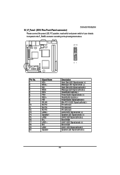
... Panel connector) Please connect the power LED, PC speaker, reset switch and power switch of your chassis front panel to the F_PANEL connector according to the pin assignment above. 20 19 21 Pin No. 1. 2. 3. 4. 5. 6. 7. 8. 9. 10. 11. 12. 13. 14. 15. 16. 17. 18. 19. 20. Description Hard Disk LED Signal anode (+) Message LED Signal anode (+) Hard Disk LED Signal cathode(-) Message LED Signal cathode(-) Reset Button cathode(-) Power Button Signal anode (+) Reset Button anode (+) Power Button Signal cathode(-) Mini PCI-E LED Signal cathode(-) Pin removed Pin removed Pin removed LAN 2 LED...
... Panel connector) Please connect the power LED, PC speaker, reset switch and power switch of your chassis front panel to the F_PANEL connector according to the pin assignment above. 20 19 21 Pin No. 1. 2. 3. 4. 5. 6. 7. 8. 9. 10. 11. 12. 13. 14. 15. 16. 17. 18. 19. 20. Description Hard Disk LED Signal anode (+) Message LED Signal anode (+) Hard Disk LED Signal cathode(-) Message LED Signal cathode(-) Reset Button cathode(-) Power Button Signal anode (+) Reset Button anode (+) Power Button Signal cathode(-) Mini PCI-E LED Signal cathode(-) Pin removed Pin removed Pin removed LAN 2 LED...

Manual
Page 28
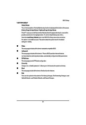
... turned off, the battery on , press the button during the BIOS POST (Power-On Self Test) will take you to activate certain system features. GA-6KIEH-RH/GA-6KIEL-RH Motherboard Chapter 3 BIOS Setup BIOS (Basic Input and Output System) includes a CMOS SETUP utility which allows user to configure required settings or to the CMOS SETUP screen. You can enter the BIOS setup screen by pressing "Ctrl + F1". The CMOS SETUP saves the configuration in the left hand Move to Main Menu...
... turned off, the battery on , press the button during the BIOS POST (Power-On Self Test) will take you to activate certain system features. GA-6KIEH-RH/GA-6KIEL-RH Motherboard Chapter 3 BIOS Setup BIOS (Basic Input and Output System) includes a CMOS SETUP utility which allows user to configure required settings or to the CMOS SETUP screen. You can enter the BIOS setup screen by pressing "Ctrl + F1". The CMOS SETUP saves the configuration in the left hand Move to Main Menu...
Manual
Page 29
... Phoenix BIOS special enhanced features. (ex: Auto detect fan and temperature status, automatically configure hard disk parameters.) z TPM State This setup page provide TPM state configuration z Security Change, set, or disable password. To exit the Help Window press . Status Page Setup Menu / Option Page Setup Menu Press F1 to pop up a small help window that describes the appropriate keys to limit access the system and setup. Select the Load Setup Defaults item in standard compatible BIOS. GETTINGHELP BIOS Setup Main Menu The...
... Phoenix BIOS special enhanced features. (ex: Auto detect fan and temperature status, automatically configure hard disk parameters.) z TPM State This setup page provide TPM state configuration z Security Change, set, or disable password. To exit the Help Window press . Status Page Setup Menu / Option Page Setup Menu Press F1 to pop up a small help window that describes the appropriate keys to limit access the system and setup. Select the Load Setup Defaults item in standard compatible BIOS. GETTINGHELP BIOS Setup Main Menu The...

Manual
Page 31
... at a time if the device supports it. The hard disk will automatically detect HDD type. TYPE 1-39: Predefined types. Auto: Set parameters automatically. (Default setting) CD-ROM: Use for this category. SMART Monitoring This filed allows allows your drive must match with the drive table. Users: Set parameters by User. Note that has been installed in the specific IDE channel. Auto: The data transfer from drive 1 to max imize the IDE data transfer rate. Transfer Mode This field shows the information...
... at a time if the device supports it. The hard disk will automatically detect HDD type. TYPE 1-39: Predefined types. Auto: Set parameters automatically. (Default setting) CD-ROM: Use for this category. SMART Monitoring This filed allows allows your drive must match with the drive table. Users: Set parameters by User. Note that has been installed in the specific IDE channel. Auto: The data transfer from drive 1 to max imize the IDE data transfer rate. Transfer Mode This field shows the information...
Manual
Page 37
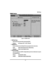
DVMT 4.0 Mode Select the configuration of DVMT 4.0 Graphics Memory that will allocate for use by setting this item to desire value. Fixed DVMT Disable DVMT 4.0 Mode. IGDDevice 2 Enable or disable the Internal Graphics Device by the internal graphic device. Enable DVMT 4.0 Mode. (Default setting) 37 GM965 Feature BIOS Setup Figure 2-3: GM965 Feature IGD Boot Type Select the Video Device that driver will be actived during POST. Auto Enable internal Graphics Device. (Default setting) Disabled Disable internal Graphics Device. Options VBT Default, CRT, TV, EFP, ...
DVMT 4.0 Mode Select the configuration of DVMT 4.0 Graphics Memory that will allocate for use by setting this item to desire value. Fixed DVMT Disable DVMT 4.0 Mode. IGDDevice 2 Enable or disable the Internal Graphics Device by the internal graphic device. Enable DVMT 4.0 Mode. (Default setting) 37 GM965 Feature BIOS Setup Figure 2-3: GM965 Feature IGD Boot Type Select the Video Device that driver will be actived during POST. Auto Enable internal Graphics Device. (Default setting) Disabled Disable internal Graphics Device. Options VBT Default, CRT, TV, EFP, ...
Manual
Page 40
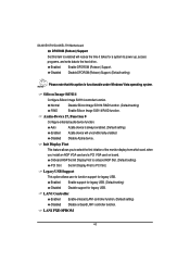
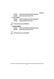
... AGP Slot. (Default setting) PCI Slot Set Init Display First to select the first initation of the monitor display from which card, when you install an AGP VGA card and a PCI VGA card on board. Normal Disable Silicon Image Sil3114 RAID function. (Default setting) RAID Enable Silicon Image Sil3114 RAID function. Enabled Enable support for legacy USB. (Default setting) Disabled Disable support for legacy USB. LAN1 Controller Enabled Enable onboard LAN1 controller function. (Default setting) Disabled Disable onboard LAN1 controller function. Silicon Image Sil3114 Configure...
... AGP Slot. (Default setting) PCI Slot Set Init Display First to select the first initation of the monitor display from which card, when you install an AGP VGA card and a PCI VGA card on board. Normal Disable Silicon Image Sil3114 RAID function. (Default setting) RAID Enable Silicon Image Sil3114 RAID function. Enabled Enable support for legacy USB. (Default setting) Disabled Disable support for legacy USB. LAN1 Controller Enabled Enable onboard LAN1 controller function. (Default setting) Disabled Disable onboard LAN1 controller function. Silicon Image Sil3114 Configure...
Manual
Page 41
LAN2 Controller Enabled Enable onboard LAN2 controller function. (Default setting) Disabled Disable onboard LAN2 controller function. Enabled Enable onboard LAN1 PXE option ROM. (Default setting) Disabled Disable onboard LAN1 PXE option ROM. This item will show up only for GA-6KIEH-RH. 41 BIOS Setup This item will show up only for GA-6KIEH-RH. LAN2 PXE OPROM Enabled Enable onboard LAN2 PXE option ROM. (Default setting) Disabled Disable onboard LAN2 PXE option ROM.
LAN2 Controller Enabled Enable onboard LAN2 controller function. (Default setting) Disabled Disable onboard LAN2 controller function. Enabled Enable onboard LAN1 PXE option ROM. (Default setting) Disabled Disable onboard LAN1 PXE option ROM. This item will show up only for GA-6KIEH-RH. 41 BIOS Setup This item will show up only for GA-6KIEH-RH. LAN2 PXE OPROM Enabled Enable onboard LAN2 PXE option ROM. (Default setting) Disabled Disable onboard LAN2 PXE option ROM.
Manual
Page 49
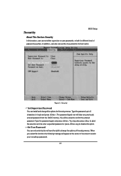
... the selection and not enter a specified password or press key to disable this function, the following message will appear at the center of the setup menus. Type the password again and press . Figure 3: Security Set Supervisor Password You can set either supervisor or user passwords, or both for the setup menus. In addition, user also can install and change the options of the screen to 6 characters in creating...
... the selection and not enter a specified password or press key to disable this function, the following message will appear at the center of the setup menus. Type the password again and press . Figure 3: Security Set Supervisor Password You can set either supervisor or user passwords, or both for the setup menus. In addition, user also can install and change the options of the screen to 6 characters in creating...
Manual
Page 50
... on boot. Enabled Enable TPM Support. (Default setting) Disabled Disable TPM Support. 50 Disabled Disable this item will be required when system on boot. You will be adjustable when supervision password is set. A Trusted Platform Module provides function for Trusted Platform Module. GA-6KIEH-RH/GA-6KIEL-RH Motherboard Type the password up to abort the selection and not enter a specified password. The password typed now will be asked to limit the use of cryptographic keys, as...
... on boot. Enabled Enable TPM Support. (Default setting) Disabled Disable TPM Support. 50 Disabled Disable this item will be required when system on boot. You will be adjustable when supervision password is set. A Trusted Platform Module provides function for Trusted Platform Module. GA-6KIEH-RH/GA-6KIEL-RH Motherboard Type the password up to abort the selection and not enter a specified password. The password typed now will be asked to limit the use of cryptographic keys, as...


