Manual
Page 3
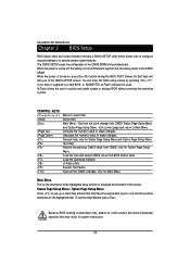
... 2Hardware Installation Process 9 2-1: Installing Memory Module 9 2-2: Connect ribbon cables, cabinet wires, and power supply 10 2-2-1 : I/O Back Panel Introduction 10 2-3: Connectors Introduction & Jumper Setting 13 2-4: Block Diagram 24 Chapter 3 BIOS Setup 25 The Main Menu (For example: BIOS Ver. : F1 26 3-1 Standard CMOS Features 28 3-2 Advanced BIOS Features 30 3-3 Integrated Peripherals 32 3-4 Power Management Setup 34 3-5 PC Health Status ...35 3-6 Frequency/Voltage Control 36 3-7 Load Fail-Safe Defaults 37 3-8 Load Optimized Defaults 37 3-9 Set Supervisor/User Password...
... 2Hardware Installation Process 9 2-1: Installing Memory Module 9 2-2: Connect ribbon cables, cabinet wires, and power supply 10 2-2-1 : I/O Back Panel Introduction 10 2-3: Connectors Introduction & Jumper Setting 13 2-4: Block Diagram 24 Chapter 3 BIOS Setup 25 The Main Menu (For example: BIOS Ver. : F1 26 3-1 Standard CMOS Features 28 3-2 Advanced BIOS Features 30 3-3 Integrated Peripherals 32 3-4 Power Management Setup 34 3-5 PC Health Status ...35 3-6 Frequency/Voltage Control 36 3-7 Load Fail-Safe Defaults 37 3-8 Load Optimized Defaults 37 3-9 Set Supervisor/User Password...
Manual
Page 5
...) cuff when handling electronic components (CPU, RAM). 4. Prior to the use of uncertified components. 5. Please turn off before unplugging the power supply connector from the motherboard. Installation Notices 1. If you are no leftover screws or metal components placed on the motherboard. Before using the product, please verify that the power supply is best to installation, please follow the instructions below: 1. GA-6JIEV2-RH Motherboard Chapter 1 Introduction 1-1 Considerations Prior to...
...) cuff when handling electronic components (CPU, RAM). 4. Prior to the use of uncertified components. 5. Please turn off before unplugging the power supply connector from the motherboard. Installation Notices 1. If you are no leftover screws or metal components placed on the motherboard. Before using the product, please verify that the power supply is best to installation, please follow the instructions below: 1. GA-6JIEV2-RH Motherboard Chapter 1 Introduction 1-1 Considerations Prior to...

Manual
Page 6
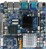
...; Supports 1 PCI slot 32-Bit/33MHz Supports 1 mini card slot (PCI-E x1/ USB 2.0) Intel® ICH6M Build in Intel® 910GMLE chipset Shared system memory up to 128MB Relteak®ALC 883 chipset 2 x SATA connectors 1 x IDE connector 1 x Serial connectors (COM) 1 x front audio connector 1 x USB 2.0 connectors for additional 2 ports by cable 1 x front panel connecctor 1 x System fan cable connector 1 x CPU fan cable connector 1 x DC power jack 1 x VGA port...
...; Supports 1 PCI slot 32-Bit/33MHz Supports 1 mini card slot (PCI-E x1/ USB 2.0) Intel® ICH6M Build in Intel® 910GMLE chipset Shared system memory up to 128MB Relteak®ALC 883 chipset 2 x SATA connectors 1 x IDE connector 1 x Serial connectors (COM) 1 x front audio connector 1 x USB 2.0 connectors for additional 2 ports by cable 1 x front panel connecctor 1 x System fan cable connector 1 x CPU fan cable connector 1 x DC power jack 1 x VGA port...

Manual
Page 7
GA-6JIEV2-RH Motherboard BIOS Additional Features AWARD BIOS on 4Mb Flash ROM External Modem wake up Supports S1, S3, S4, S5 under Windows Operating System Wake on LAN (WOL) Supports Console Redirection Supports 3-pin Fan controller 7
GA-6JIEV2-RH Motherboard BIOS Additional Features AWARD BIOS on 4Mb Flash ROM External Modem wake up Supports S1, S3, S4, S5 under Windows Operating System Wake on LAN (WOL) Supports Console Redirection Supports 3-pin Fan controller 7

Manual
Page 11
... the keyboard to Serial port. VGA Port Connect the monitor cable to this port. GA-6JIEV2-RH Motherboard DC Power Jack Connect the DC power to this port. MIC In The default MIC In jack. LAN Port The LAN port provides Internet connection of Gigabit Ethernet with data transfer speeds of 10/100/1000Mbps. USB Before you connect your device(s) into USB connector(s), please make sure your OS does not support USB controller, please contact OS vendor for possible patch or driver updated. Line...
... the keyboard to Serial port. VGA Port Connect the monitor cable to this port. GA-6JIEV2-RH Motherboard DC Power Jack Connect the DC power to this port. MIC In The default MIC In jack. LAN Port The LAN port provides Internet connection of Gigabit Ethernet with data transfer speeds of 10/100/1000Mbps. USB Before you connect your device(s) into USB connector(s), please make sure your OS does not support USB controller, please contact OS vendor for possible patch or driver updated. Line...
Manual
Page 14
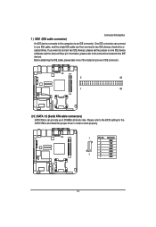
... IDE device connects to 300MB/s stransfer rate. One IDE connector can connect to one IDE device as Master and the other as Slave (for the SATA 3Gb/s and install the proper driver in IDE connector. 2 44 1 43 2/3 ) SATA 1/2 (Serial ATA cable connectors) SATA 3Gb/s can then connect to two IDE devices (hard drive or optical drive). Please refer to the BIOS setting for information, please refer to work properly. 1 Pin No. If you want to connect two IDE devices, please set the jumper...
... IDE device connects to 300MB/s stransfer rate. One IDE connector can connect to one IDE device as Master and the other as Slave (for the SATA 3Gb/s and install the proper driver in IDE connector. 2 44 1 43 2/3 ) SATA 1/2 (Serial ATA cable connectors) SATA 3Gb/s can then connect to two IDE devices (hard drive or optical drive). Please refer to the BIOS setting for information, please refer to work properly. 1 Pin No. If you want to connect two IDE devices, please set the jumper...

Manual
Page 19
...CPU_FAN connector to prevent CPU damage or system hanging caused by overheating. 1 Pin No. A red power connector wire indicates a positive connection and requires a +12V power voltage. The black connector wire is the ground wire (GND). Definition 1 12V 2 GND 3 GND 4 5V 19 Most coolers are designed with color-coded power connector wires. Definition 1 GND 2 12V 3 Sense 17 ) PWR1 (Power Output connector) 1 Pin No. GA-6JIEV2-RH Motherboard 16 ) CPU_FAN1 (CPU fan cable connector) The cooler fan power connector supplies a +12V power voltage via a 3-pin power connector and...
...CPU_FAN connector to prevent CPU damage or system hanging caused by overheating. 1 Pin No. A red power connector wire indicates a positive connection and requires a +12V power voltage. The black connector wire is the ground wire (GND). Definition 1 12V 2 GND 3 GND 4 5V 19 Most coolers are designed with color-coded power connector wires. Definition 1 GND 2 12V 3 Sense 17 ) PWR1 (Power Output connector) 1 Pin No. GA-6JIEV2-RH Motherboard 16 ) CPU_FAN1 (CPU fan cable connector) The cooler fan power connector supplies a +12V power voltage via a 3-pin power connector and...

Manual
Page 21
Description Hard Disk LED Signal anode (+) Message LED Signal anode (+) Hard Disk LED Signal cathode(-) Message LED Signal cathode(-) Reset Button anode (+) Power Button Signal cathode(-) Reset Button cathode(-) Power Button Signal anode (+) No connect Pin removed Pin removed Pin removed Pin removed Speaker LED Signal anode (+) Pin removed No connect Pin removed No connect Pin removed Speaker LED Signal cathode(-) 21 GA-6JIEV2-RH Motherboard 19 ) F_Panel (2X10 Pins Front Panel connector) Please connect the power LED, PC speaker, reset switch and power switch of your chassis front panel to ...
Description Hard Disk LED Signal anode (+) Message LED Signal anode (+) Hard Disk LED Signal cathode(-) Message LED Signal cathode(-) Reset Button anode (+) Power Button Signal cathode(-) Reset Button cathode(-) Power Button Signal anode (+) No connect Pin removed Pin removed Pin removed Pin removed Speaker LED Signal anode (+) Pin removed No connect Pin removed No connect Pin removed Speaker LED Signal cathode(-) 21 GA-6JIEV2-RH Motherboard 19 ) F_Panel (2X10 Pins Front Panel connector) Please connect the power LED, PC speaker, reset switch and power switch of your chassis front panel to ...
Manual
Page 25
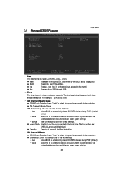
... displayed at the bottom of the motherboard. CONTROL KEYS Enter> Move to activate certain system features. Exit current page and return to Main Menu Increase the numeric value or make changes Decrease the numeric value or make changes General help window that may result in the CMOS SRAM of the screen. GA-6JIEV2-RH Motherboard Chapter 3 BIOS Setup BIOS (Basic Input and Output System) includes a CMOS SETUP utility which allows user to configure required settings...
... displayed at the bottom of the motherboard. CONTROL KEYS Enter> Move to activate certain system features. Exit current page and return to Main Menu Increase the numeric value or make changes Decrease the numeric value or make changes General help window that may result in the CMOS SRAM of the screen. GA-6JIEV2-RH Motherboard Chapter 3 BIOS Setup BIOS (Basic Input and Output System) includes a CMOS SETUP utility which allows user to configure required settings...

Manual
Page 26
..., the Main Menu (as usual. CMOS Setup Utility-Copyright (C) 1984-2006 Award Software Standard CMOS Features Advanced BIOS Features Integrated Peripherals Power Management Setup PC Health Status Frequency/Voltage Control Load Fail-Safe Defaults Load Optimized Defaults Set Supervisor Password Set User Password Save & Exit Setup Exit Without Saving ESC: Quit F8: Q-Flash Select Item F10: Save & Exit Setup Time, Date, Hard Disk Type... 1. This action makes the system reset to the default settings for your motherboard. 26 Use...
..., the Main Menu (as usual. CMOS Setup Utility-Copyright (C) 1984-2006 Award Software Standard CMOS Features Advanced BIOS Features Integrated Peripherals Power Management Setup PC Health Status Frequency/Voltage Control Load Fail-Safe Defaults Load Optimized Defaults Set Supervisor Password Set User Password Save & Exit Setup Exit Without Saving ESC: Quit F8: Q-Flash Select Item F10: Save & Exit Setup Time, Date, Hard Disk Type... 1. This action makes the system reset to the default settings for your motherboard. 26 Use...
Manual
Page 27
... is the System auto detect Temperature, voltage, fan, speed. Frequency/Voltage Control This setup page is control CPU clock and frequency ratio. Load Fail-Safe Defaults Fail-Safe Defaults indicates the value of the system parameters which the system would be in best performance configuration. Set Supervisor Password Change, set , or disable password. GA-6JIEV2-RH Motherboard Standard CMOS Features This setup page includes all the items in standard compatible BIOS. Advanced BIOS Features This setup page includes all the...
... is the System auto detect Temperature, voltage, fan, speed. Frequency/Voltage Control This setup page is control CPU clock and frequency ratio. Load Fail-Safe Defaults Fail-Safe Defaults indicates the value of the system parameters which the system would be in best performance configuration. Set Supervisor Password Change, set , or disable password. GA-6JIEV2-RH Motherboard Standard CMOS Features This setup page includes all the items in standard compatible BIOS. Advanced BIOS Features This setup page includes all the...
Manual
Page 28
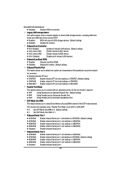
... automatic device detection. IDE Channel 2 Master IDE HDD Auto-Detection Press "Enter" to set the access mode for automatic device detection. IDE Channel 0 Master/Slave IDE devices setup. 3-1 Standard CMOS Features BIOS Setup Date (mm:dd:yy) Time (hh:mm:ss) CMOS Setup Utility-Copyright (C) 1984-2006 Award Software Standard CMOS Features Wed, Apr 8 2009 14:31:24 Item Help Menu Level IDE Channel 0 Master IDE Channel 0 Slave IDE Channel 2 Master [None] [None] [None] Base Memory Extended Memory Total Memory BIOS Version 640K...
... automatic device detection. IDE Channel 2 Master IDE HDD Auto-Detection Press "Enter" to set the access mode for automatic device detection. IDE Channel 0 Master/Slave IDE devices setup. 3-1 Standard CMOS Features BIOS Setup Date (mm:dd:yy) Time (hh:mm:ss) CMOS Setup Utility-Copyright (C) 1984-2006 Award Software Standard CMOS Features Wed, Apr 8 2009 14:31:24 Item Help Menu Level IDE Channel 0 Master IDE Channel 0 Slave IDE Channel 2 Master [None] [None] [None] Base Memory Extended Memory Total Memory BIOS Version 640K...

Manual
Page 30
... correct password is not entered at the prompt. (Default setting) Limit CPUID Max. 3-2 Advanced BIOS Features BIOS Setup CMOS Setup Utility-Copyright (C) 1984-2006 Award Software Advanced BIOS Features Hard Disk Boot Priority First Boot Device [Press Enter] [Floppy] Item Help Menu Level Second Boot Device Third Boot Device Password Check Limit CPUID Max. to move it down the list. Use < > or < > to select a device, then press to move it up, or to 3 Init Display First On-Chip Frame Buffer Size [Hard Disk] [CDROM] [Setup] [Enabled] [PCI...
... correct password is not entered at the prompt. (Default setting) Limit CPUID Max. 3-2 Advanced BIOS Features BIOS Setup CMOS Setup Utility-Copyright (C) 1984-2006 Award Software Advanced BIOS Features Hard Disk Boot Priority First Boot Device [Press Enter] [Floppy] Item Help Menu Level Second Boot Device Third Boot Device Password Check Limit CPUID Max. to move it down the list. Use < > or < > to select a device, then press to move it up, or to 3 Init Display First On-Chip Frame Buffer Size [Hard Disk] [CDROM] [Setup] [Enabled] [PCI...

Manual
Page 32
... Set PATA IDE to 4 HDDs on the motherboard; 2 for SATA and the other for PATA. On-Chip SATA Mode Disabled Auto Disable this function will auto make by the setting "On-Chip SATA Mode" and "PATA IDE Set to PATA mode. 3-3 Integrated Peripherals BIOS Setup CMOS Setup Utility-Copyright (C) 1984-2006 Award Software Integrated Peripherals On-Chip Primary PCI IDE On-Chip SATA Mode x PATA IDE Set to SATA Port 0/2 Set to USB Controller USB 2.0 Controller Legacy USB storage detect Onboard Lan Controller Onboard Lan Boot ROM Onboard Parallel Port ECP Mode Use DMA Onboard Serial...
... Set PATA IDE to 4 HDDs on the motherboard; 2 for SATA and the other for PATA. On-Chip SATA Mode Disabled Auto Disable this function will auto make by the setting "On-Chip SATA Mode" and "PATA IDE Set to PATA mode. 3-3 Integrated Peripherals BIOS Setup CMOS Setup Utility-Copyright (C) 1984-2006 Award Software Integrated Peripherals On-Chip Primary PCI IDE On-Chip SATA Mode x PATA IDE Set to SATA Port 0/2 Set to USB Controller USB 2.0 Controller Legacy USB storage detect Onboard Lan Controller Onboard Lan Boot ROM Onboard Parallel Port ECP Mode Use DMA Onboard Serial...
Manual
Page 33
...Lan Boot ROM Enabled Onboard Lan Boot ROM. This function will scan all onboard LAN devices. (Default setting) Only Used LAN1 Enable onboard LAN1 device. Enable onboard Serial port 1 and address is 2E8/IRQ3. Enable onboard Serial port 1 and address is 2E8/IRQ3. Only Used LAN2 Enable onboard LAN2 device. Disabled Disable this function. Parallel Port Mode This feature allows you to 1. GA-6JIEV2-RH Motherboard Disabled Disable USB 2.0 controller. Legacy USB storage detect This option allows users to decide whether to connect with an advanced printer via the port...
...Lan Boot ROM Enabled Onboard Lan Boot ROM. This function will scan all onboard LAN devices. (Default setting) Only Used LAN1 Enable onboard LAN1 device. Enable onboard Serial port 1 and address is 2E8/IRQ3. Enable onboard Serial port 1 and address is 2E8/IRQ3. Only Used LAN2 Enable onboard LAN2 device. Disabled Disable this function. Parallel Port Mode This feature allows you to 1. GA-6JIEV2-RH Motherboard Disabled Disable USB 2.0 controller. Legacy USB storage detect This option allows users to decide whether to connect with an advanced printer via the port...

Manual
Page 34
... system always in Date/Time to Power off instantly. (Default setting) Delay 4 Sec. Press power button 4 sec. If Resume by Alarm is pressed less than 4 sec. Disabled Disable this function. (Default value) Enabled Enable alarm function to Power ON Suspend under ACPI OS. (Default setting) S1 (POS) Set the suspend type to POWER ON system. 3-4 Power Management Setup BIOS Setup CMOS Setup Utility-Copyright (C) 1984-2006 Award Software Power Management Setup ACPI Suspend Type Soft-Off by PWR-BTTN AC...
... system always in Date/Time to Power off instantly. (Default setting) Delay 4 Sec. Press power button 4 sec. If Resume by Alarm is pressed less than 4 sec. Disabled Disable this function. (Default value) Enabled Enable alarm function to Power ON Suspend under ACPI OS. (Default setting) S1 (POS) Set the suspend type to POWER ON system. 3-4 Power Management Setup BIOS Setup CMOS Setup Utility-Copyright (C) 1984-2006 Award Software Power Management Setup ACPI Suspend Type Soft-Off by PWR-BTTN AC...
Manual
Page 35
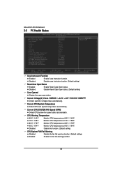
...90oC / 194oF Monitor CPU temperature at 90oC / 194oF. Disable Reset Case Open status. (Default setting) Case Opened Display the case open status. GA-6JIEV2-RH Motherboard 3-5 PC Health Status CMOS Setup Utility-Copyright (C) 1984-2006 Award Software PC Health Status Case Instrusion Function Reset Case Open Status Case Opened Vcore DDR18V +3.3V +12V VCC15V DDRVTT Current SYSTEM Temperature Current CPU Temperature Current CPU FAN Speed Current SYSTEM FAN Speed SYSTEM Warning Temperature CPU Warning Temperature CPU FAN Fail Warning SYSTEM FAN Fail Warning [Disabled] [Disabled] Yes 0.992V...
...90oC / 194oF Monitor CPU temperature at 90oC / 194oF. Disable Reset Case Open status. (Default setting) Case Opened Display the case open status. GA-6JIEV2-RH Motherboard 3-5 PC Health Status CMOS Setup Utility-Copyright (C) 1984-2006 Award Software PC Health Status Case Instrusion Function Reset Case Open Status Case Opened Vcore DDR18V +3.3V +12V VCC15V DDRVTT Current SYSTEM Temperature Current CPU Temperature Current CPU FAN Speed Current SYSTEM FAN Speed SYSTEM Warning Temperature CPU Warning Temperature CPU FAN Fail Warning SYSTEM FAN Fail Warning [Disabled] [Disabled] Yes 0.992V...
Manual
Page 38
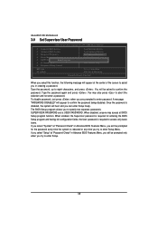
... password. Type the password, up to confirm the password. Once the password is rebooted or any time you in Advance BIOS Features Menu, you will boot and you can enter Setup freely. GA-6JIEV2-RH Motherboard 3-9 Set Supervisor/User Password CMOS Setup Utility-Copyright (C) 1984-2006 Award Software Standard CMOS Features Advanced BIOS Features Integrated Peripherals Power Management Setup PnP/PCI ConfiguratioEnsnter Password: PC Health Status Frequency/Voltage Control Load Fail-Safe Defaults Load Optimized Defaults...
... password. Type the password, up to confirm the password. Once the password is rebooted or any time you in Advance BIOS Features Menu, you will boot and you can enter Setup freely. GA-6JIEV2-RH Motherboard 3-9 Set Supervisor/User Password CMOS Setup Utility-Copyright (C) 1984-2006 Award Software Standard CMOS Features Advanced BIOS Features Integrated Peripherals Power Management Setup PnP/PCI ConfiguratioEnsnter Password: PC Health Status Frequency/Voltage Control Load Fail-Safe Defaults Load Optimized Defaults...
Manual
Page 40
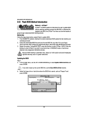
... the Q-Flash menu, use the Save BIOS to Drive function. During BIOS POST, press the End key to update BIOS: 1. b. GA-6JIEV2-RH Motherboard 3-12 Flash BIOS Method Introduction Method 1 : Q-FlashTM Q-FlashTM is a BIOS update tool that allows the user to update BIOS without entering operating systems like MS-DOS or Windows.Embedded in the BIOS, the Q-FlashTM tool frees you from Drive Sa0vfeilBe(IOs)SfotounDdrive EnteFr l:oRppuyn A :Move ESC:Reset :Power Off HDD 0-0 Total size : 0 F5 : Refresh Free size...
... the Q-Flash menu, use the Save BIOS to Drive function. During BIOS POST, press the End key to update BIOS: 1. b. GA-6JIEV2-RH Motherboard 3-12 Flash BIOS Method Introduction Method 1 : Q-FlashTM Q-FlashTM is a BIOS update tool that allows the user to update BIOS without entering operating systems like MS-DOS or Windows.Embedded in the BIOS, the Q-FlashTM tool frees you from Drive Sa0vfeilBe(IOs)SfotounDdrive EnteFr l:oRppuyn A :Move ESC:Reset :Power Off HDD 0-0 Total size : 0 F5 : Refresh Free size...

Manual
Page 41
...the BIOS file from the floppy disk is reading/updating the BIOS. 2. Do not turn off or restart the system when the system is displayed on the screen. Q-Flash Utility v2.02 Flash Type/Size MXIC SPI Serial F1a 512K Enter : Run Keep DMI Data Enable !! CMOS Setup Utility-Copyright (C) 1984-2006 Award Software Standard CMOS Features Load Fail-Safe Defaults Advanced BIOS Features Load Optimized Defaults Integrated Peripherals Set Supervisor Password Power Management Setup Set User Password PnP/PCI Configurations Load Optimized Defaults...
...the BIOS file from the floppy disk is reading/updating the BIOS. 2. Do not turn off or restart the system when the system is displayed on the screen. Q-Flash Utility v2.02 Flash Type/Size MXIC SPI Serial F1a 512K Enter : Run Keep DMI Data Enable !! CMOS Setup Utility-Copyright (C) 1984-2006 Award Software Standard CMOS Features Load Fail-Safe Defaults Advanced BIOS Features Load Optimized Defaults Integrated Peripherals Set Supervisor Password Power Management Setup Set User Password PnP/PCI Configurations Load Optimized Defaults...


