Manual
Page 1
GA-6JIEV2-RH Intel® mini-ITX Motherboard USER'S MANUAL Intel® mini-ITX Motherboard Rev. 1001 * The WEEE marking on the product indicates this product must not be disposed of with user's other household waste and must be handed over to a designated collection point for the recycling of waste electrical and electronic equipment!! * The WEEE marking applies only in European Union's member states.
GA-6JIEV2-RH Intel® mini-ITX Motherboard USER'S MANUAL Intel® mini-ITX Motherboard Rev. 1001 * The WEEE marking on the product indicates this product must not be disposed of with user's other household waste and must be handed over to a designated collection point for the recycling of waste electrical and electronic equipment!! * The WEEE marking applies only in European Union's member states.

Manual
Page 2
...or by any means without prior notice. For more product details, please click onto Gigabyte's website at www.gigabyte.com.tw The trademarks mentioned in the use of Gigabyte. Specifications and features are legally registered to their respective companies. All rights reserved. ...please carefully read the "Product User Manual". For detailed information related to Gigabyte's unique features, please go to "Technology Guide" section on Gigabyte's website to change without Gigabyte's prior written permission. Product Manual Classification In order to assist in the manual are...
...or by any means without prior notice. For more product details, please click onto Gigabyte's website at www.gigabyte.com.tw The trademarks mentioned in the use of Gigabyte. Specifications and features are legally registered to their respective companies. All rights reserved. ...please carefully read the "Product User Manual". For detailed information related to Gigabyte's unique features, please go to "Technology Guide" section on Gigabyte's website to change without Gigabyte's prior written permission. Product Manual Classification In order to assist in the manual are...
Manual
Page 3
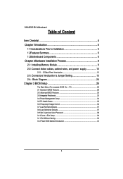
GA-6JIEV2-RH Motherboard Table of Content Item Checklist 4 Chapter 1Introduction 5 1-1Considerations Prior to Installation 5 1.2Features Summary 6 1.3Motherboard Components 8 Chapter 2Hardware Installation Process 9 2-1: Installing Memory Module 9 2-2: Connect ribbon ...
GA-6JIEV2-RH Motherboard Table of Content Item Checklist 4 Chapter 1Introduction 5 1-1Considerations Prior to Installation 5 1.2Features Summary 6 1.3Motherboard Components 8 Chapter 2Hardware Installation Process 9 2-1: Installing Memory Module 9 2-2: Connect ribbon ...

Manual
Page 4
Item Checklist The GA-6JIEV2-RH motherboard I/O Shield Kit CD for motherboard driver & utility GA-6JIEV2-RH Quick Reference Guide Power cable x 1 B4P/S4P Cable x 1 Optional Power Adapter x 1 Introduction * The items listed above are for reference only, and are subject to change without notice. 4
Item Checklist The GA-6JIEV2-RH motherboard I/O Shield Kit CD for motherboard driver & utility GA-6JIEV2-RH Quick Reference Guide Power cable x 1 B4P/S4P Cable x 1 Optional Power Adapter x 1 Introduction * The items listed above are for reference only, and are subject to change without notice. 4
Manual
Page 5
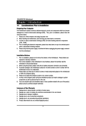
... to installing the electronic components, please have a problem related to use of uncertified components. 5. Prior to be an unofficial Gigabyte product. 5 Please do not remove the stickers on top of an antistatic pad or within the computer casing. 6. If ... that the power supply is best to wear an electrostatic discharge (ESD) cuff when handling electronic components (CPU, RAM). 4. GA-6JIEV2-RH Motherboard Chapter 1 Introduction 1-1 Considerations Prior to Installation Preparing Your Computer The motherboard contains numerous delicate electronic circuits and components which can...
... to installing the electronic components, please have a problem related to use of uncertified components. 5. Prior to be an unofficial Gigabyte product. 5 Please do not remove the stickers on top of an antistatic pad or within the computer casing. 6. If ... that the power supply is best to wear an electrostatic discharge (ESD) cuff when handling electronic components (CPU, RAM). 4. GA-6JIEV2-RH Motherboard Chapter 1 Introduction 1-1 Considerations Prior to Installation Preparing Your Computer The motherboard contains numerous delicate electronic circuits and components which can...

Manual
Page 6
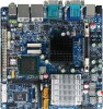
1.2 Features Summary Hardware Installation Process Form Factor CPU Chipset Memory I/O Control Expansion Slots SATA Controller On-Board Graphic On-Board Sound Internal Connector Rear Panel I/O Hardware Monitor On-Board LAN 170mm x 170mm Mini ITX form factor, 8 layers PCB. Supports single Intel® ULV CeleronM processor Supports 1GHz Intel® 910GMLE MCH Intel® ICH6M 1 x DDR2 DIMM SO-DIMM socket Supports up to 2GB 400 memory Supports 1.8V DDR2 DIMMs ITE IT8781F Super I/O Supports 1 PCI slot 32...
1.2 Features Summary Hardware Installation Process Form Factor CPU Chipset Memory I/O Control Expansion Slots SATA Controller On-Board Graphic On-Board Sound Internal Connector Rear Panel I/O Hardware Monitor On-Board LAN 170mm x 170mm Mini ITX form factor, 8 layers PCB. Supports single Intel® ULV CeleronM processor Supports 1GHz Intel® 910GMLE MCH Intel® ICH6M 1 x DDR2 DIMM SO-DIMM socket Supports up to 2GB 400 memory Supports 1.8V DDR2 DIMMs ITE IT8781F Super I/O Supports 1 PCI slot 32...
Manual
Page 7
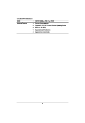
GA-6JIEV2-RH Motherboard BIOS Additional Features AWARD BIOS on 4Mb Flash ROM External Modem wake up Supports S1, S3, S4, S5 under Windows Operating System Wake on LAN (WOL) Supports Console Redirection Supports 3-pin Fan controller 7
GA-6JIEV2-RH Motherboard BIOS Additional Features AWARD BIOS on 4Mb Flash ROM External Modem wake up Supports S1, S3, S4, S5 under Windows Operating System Wake on LAN (WOL) Supports Console Redirection Supports 3-pin Fan controller 7
Manual
Page 9
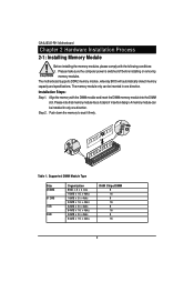
... 16MB x 16 x 4bks 16MB x 8 x 4bks 32MB x 16 x 4bks 32MB x 8 x 4bks 64MB x 16 x 4bks 32MB x 8 x 4bks 64MB x 16 x 4bks RAM Chips/DIMM 8 16 8 16 8 16 8 16 9 GA-6JIEV2-RH Motherboard Chapter 2 Hardware Installation Process 2-1: Installing Memory Module Before installing the memory modules, please comply with the DIMM module and insert the DIMM memory module...
... 16MB x 16 x 4bks 16MB x 8 x 4bks 32MB x 16 x 4bks 32MB x 8 x 4bks 64MB x 16 x 4bks 32MB x 8 x 4bks 64MB x 16 x 4bks RAM Chips/DIMM 8 16 8 16 8 16 8 16 9 GA-6JIEV2-RH Motherboard Chapter 2 Hardware Installation Process 2-1: Installing Memory Module Before installing the memory modules, please comply with the DIMM module and insert the DIMM memory module...

Manual
Page 10
Hardware Installation Process 2-2: Connect ribbon cables, cabinet wires, and power supply 2-2-1 : I/O Back Panel Introduction 10
Hardware Installation Process 2-2: Connect ribbon cables, cabinet wires, and power supply 2-2-1 : I/O Back Panel Introduction 10

Manual
Page 11
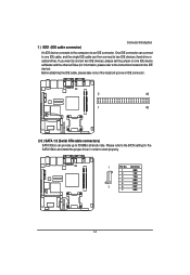
... possible patch or driver updated. Stereo speakers, earphone or front surround speakers can be connected to Serial port. Microphone must be connected to this port. GA-6JIEV2-RH Motherboard DC Power Jack Connect the DC power to MIC In jack. 11 USB Before you connect your device(s) into USB connector(s), please make sure...
... possible patch or driver updated. Stereo speakers, earphone or front surround speakers can be connected to Serial port. Microphone must be connected to this port. GA-6JIEV2-RH Motherboard DC Power Jack Connect the DC power to MIC In jack. 11 USB Before you connect your device(s) into USB connector(s), please make sure...

Manual
Page 12
LAN LED Description LED2 (Green/Yellow) Hardware Installation Process LED1 (Green) Name LED1 LED2 Color Green Green Green Green Yellow Yellow Condition ON BLINK OFF OFF OFF ON BLINK ON BLINK Description LAN Link / no Access LAN Access Idle 10Mbps connection Port identification with 10 Mbps connection 100Mbps connection Port identification with 100Mbps connection 1Gbps connection Port identification with 1Gbps connection 12
LAN LED Description LED2 (Green/Yellow) Hardware Installation Process LED1 (Green) Name LED1 LED2 Color Green Green Green Green Yellow Yellow Condition ON BLINK OFF OFF OFF ON BLINK ON BLINK Description LAN Link / no Access LAN Access Idle 10Mbps connection Port identification with 10 Mbps connection 100Mbps connection Port identification with 100Mbps connection 1Gbps connection Port identification with 1Gbps connection 12

Manual
Page 13
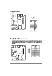
PWR1 18. COM4 5. LVDS_CTL2 9. LVDS_PSEL1 12. CPU_FAN1 17. LPT1 19. F_PANEL1 (Front panel connector) 20. IDE1 (IDE cable connector) 2. LVDS_CTL1 8. RI_S5 15. BAT1 21. F_AUDIO1 7. RI_S2 13. GPIO1 22. SATA1 (SATA cable connector) 3. SJ2 11. RI_S3 14. CF_S1 23. CLR_CMOS 13 SATA2 (SATA cable connector) 4. SJ1 10. F_USB1 (Fornt USB cable connector) 6. RI_S4 16. GA-6JIEV2-RH Motherboard 2-3: Connectors Introduction & Jumper Setting 6 79 11 12 13 10 14 8 21 16 23 22 5 3 15 1 20 17 4 18 2 19 1.
PWR1 18. COM4 5. LVDS_CTL2 9. LVDS_PSEL1 12. CPU_FAN1 17. LPT1 19. F_PANEL1 (Front panel connector) 20. IDE1 (IDE cable connector) 2. LVDS_CTL1 8. RI_S5 15. BAT1 21. F_AUDIO1 7. RI_S2 13. GPIO1 22. SATA1 (SATA cable connector) 3. SJ2 11. RI_S3 14. CF_S1 23. CLR_CMOS 13 SATA2 (SATA cable connector) 4. SJ1 10. F_USB1 (Fornt USB cable connector) 6. RI_S4 16. GA-6JIEV2-RH Motherboard 2-3: Connectors Introduction & Jumper Setting 6 79 11 12 13 10 14 8 21 16 23 22 5 3 15 1 20 17 4 18 2 19 1.
Manual
Page 14
If you want to connect two IDE devices, please set the jumper on one IDE cable, and the single IDE cable can provide up to 300MB/s stransfer rate. Before attaching the IDE cable, please take note of the foolproof groove in order to two IDE devices (hard drive or optical drive). Please refer to the BIOS setting for information, please refer to the computer via an IDE connector. Definition 1 GND 2 TXP 3 TXN 4 GND 5 RXN 7 6 RXP 7 GND 14 One IDE connector can connect to one IDE device as Master and the other as Slave (for the SATA 3Gb/s and install the proper ...
If you want to connect two IDE devices, please set the jumper on one IDE cable, and the single IDE cable can provide up to 300MB/s stransfer rate. Before attaching the IDE cable, please take note of the foolproof groove in order to two IDE devices (hard drive or optical drive). Please refer to the BIOS setting for information, please refer to the computer via an IDE connector. Definition 1 GND 2 TXP 3 TXN 4 GND 5 RXN 7 6 RXP 7 GND 14 One IDE connector can connect to one IDE device as Master and the other as Slave (for the SATA 3Gb/s and install the proper ...
Manual
Page 15
For optional front USB cable, please contact your local dealer. 12 9 10 Pin No. 1 2 3 4 5 6 7 8 9 10 Definition Power Power USB DxUSB DyUSB Dx+ USB Dy+ GND GND No Pin NC 15 Check the pin assignment carefully while you connect the front USB cable, incorrect connection between the cable and connector will make the device unable to work or even damage it. GA-6JIEV2-RH Motherboard 4 ) COM4 2 10 19 Pin No. 1 2 3 4 5 6 7 8 9 10 Definition DCDSIN2 SOUT2 DTR2GND DSR2RTS2CTS2RI2NC 5 ) F_USB1 (Front USB cable connector) Be careful with the polarity of the front USB connector.
For optional front USB cable, please contact your local dealer. 12 9 10 Pin No. 1 2 3 4 5 6 7 8 9 10 Definition Power Power USB DxUSB DyUSB Dx+ USB Dy+ GND GND No Pin NC 15 Check the pin assignment carefully while you connect the front USB cable, incorrect connection between the cable and connector will make the device unable to work or even damage it. GA-6JIEV2-RH Motherboard 4 ) COM4 2 10 19 Pin No. 1 2 3 4 5 6 7 8 9 10 Definition DCDSIN2 SOUT2 DTR2GND DSR2RTS2CTS2RI2NC 5 ) F_USB1 (Front USB cable connector) Be careful with the polarity of the front USB connector.

Manual
Page 16
Also please make sure the pin assigment on the cable is the same as the pin assigment on the MB header. Definition 1 MIC_L 2 10 2 3 GND MIC_R 4 -ACZ_DEC 5 Line_R 19 6 GND 7 Faudio_JD 8 No Pin 9 Line_L 10 GND 7/8 )LVDS_CTL1/LVDS_CTL2 (LVDS panel control connectors) LVDS_CTL1 1 Pin No. In order to use Front Audio connector, you are buying support front audio connector, please contact your chassis must remove 5-6, 9-10 Jumper. Pin No. Definition 1 LBKLT_EN 2 GND 3 NC 6 4 PANEL_BKLT 5 PANEL_BKLT 6 P5V LVDS_CTL2 16 To find out if the chassis you...
Also please make sure the pin assigment on the cable is the same as the pin assigment on the MB header. Definition 1 MIC_L 2 10 2 3 GND MIC_R 4 -ACZ_DEC 5 Line_R 19 6 GND 7 Faudio_JD 8 No Pin 9 Line_L 10 GND 7/8 )LVDS_CTL1/LVDS_CTL2 (LVDS panel control connectors) LVDS_CTL1 1 Pin No. In order to use Front Audio connector, you are buying support front audio connector, please contact your chassis must remove 5-6, 9-10 Jumper. Pin No. Definition 1 LBKLT_EN 2 GND 3 NC 6 4 PANEL_BKLT 5 PANEL_BKLT 6 P5V LVDS_CTL2 16 To find out if the chassis you...

Manual
Page 17
... Definition A6GND CLK2+ CLK2GND NC GND NC NC GND Pin No. 1 3 5 7 9 11 13 15 17 19 Definition PANEL_VDD GND PANEL_VDD A0A0+ GND A1A1+ GND A2- GA-6JIEV2-RH Motherboard 9/10 ) SJ1/SJ2 (LVDS connectors) LVDS stands for Low-voltage differential signaling, which uses high-speed analog circuit techniques to provide multigigabit data transfers...
... Definition A6GND CLK2+ CLK2GND NC GND NC NC GND Pin No. 1 3 5 7 9 11 13 15 17 19 Definition PANEL_VDD GND PANEL_VDD A0A0+ GND A1A1+ GND A2- GA-6JIEV2-RH Motherboard 9/10 ) SJ1/SJ2 (LVDS connectors) LVDS stands for Low-voltage differential signaling, which uses high-speed analog circuit techniques to provide multigigabit data transfers...

Manual
Page 19
... CPU fan cable to the CPU_FAN connector to prevent CPU damage or system hanging caused by overheating. 1 Pin No. Definition 1 12V 2 GND 3 GND 4 5V 19 GA-6JIEV2-RH Motherboard 16 ) CPU_FAN1 (CPU fan cable connector) The cooler fan power connector supplies a +12V power voltage via a 3-pin power connector and possesses a foolproof connection design...
... CPU fan cable to the CPU_FAN connector to prevent CPU damage or system hanging caused by overheating. 1 Pin No. Definition 1 12V 2 GND 3 GND 4 5V 19 GA-6JIEV2-RH Motherboard 16 ) CPU_FAN1 (CPU fan cable connector) The cooler fan power connector supplies a +12V power voltage via a 3-pin power connector and possesses a foolproof connection design...

Manual
Page 21
... Pin removed Pin removed Pin removed Speaker LED Signal anode (+) Pin removed No connect Pin removed No connect Pin removed Speaker LED Signal cathode(-) 21 GA-6JIEV2-RH Motherboard 19 ) F_Panel (2X10 Pins Front Panel connector) Please connect the power LED, PC speaker, reset switch and power switch of your chassis front panel...
... Pin removed Pin removed Pin removed Speaker LED Signal anode (+) Pin removed No connect Pin removed No connect Pin removed Speaker LED Signal cathode(-) 21 GA-6JIEV2-RH Motherboard 19 ) F_Panel (2X10 Pins Front Panel connector) Please connect the power LED, PC speaker, reset switch and power switch of your chassis front panel...

Manual
Page 22
If you want to the manufacturer's instructions. Definition 1 GPI1 2 GPI2 3 GPI3 4 GPI4 5 GPI5 6 GPI6 7 GPI7 8 GPI8 9 GPO1 10 GPO2 11 GPO3 12 GPO4 13 GPO5 14 GPO6 16 15 GPO7 16 GPO8 22 20 ) BAT1 (Battery) Connector Introduction CAUTION Danger of explosion if battery is incorrectly replaced. Replace only with the same or equivalent type recommended by the manufacturer. Dispose of used batteries according to erase CMOS... 1.Turn OFF the computer and unplug the power cord. 2.Remove the battery, wait for 30 second. 3.Re-install ...
If you want to the manufacturer's instructions. Definition 1 GPI1 2 GPI2 3 GPI3 4 GPI4 5 GPI5 6 GPI6 7 GPI7 8 GPI8 9 GPO1 10 GPO2 11 GPO3 12 GPO4 13 GPO5 14 GPO6 16 15 GPO7 16 GPO8 22 20 ) BAT1 (Battery) Connector Introduction CAUTION Danger of explosion if battery is incorrectly replaced. Replace only with the same or equivalent type recommended by the manufacturer. Dispose of used batteries according to erase CMOS... 1.Turn OFF the computer and unplug the power cord. 2.Remove the battery, wait for 30 second. 3.Re-install ...
Manual
Page 23
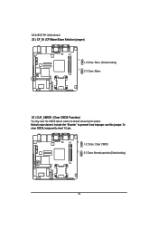
To clear CMOS, temporarily short 1-2 pin. 1 1-2 Close: Clear CMOS 1 2-3 Close: Normal operation(Default setting) 23 Default value doesn't include the "Shunter" to restore its default values by this jumper. GA-6JIEV2-RH Motherboard 22 ) CF_S1 (CF Mater/Slave Selction jumper) 1 1-2 Close: Slave. (Default setting) 1 2-3 Close: Mater. 23 ) CLR_CMOS1 (Clear CMOS Function) You may clear the CMOS data to prevent from improper use this jumper.
To clear CMOS, temporarily short 1-2 pin. 1 1-2 Close: Clear CMOS 1 2-3 Close: Normal operation(Default setting) 23 Default value doesn't include the "Shunter" to restore its default values by this jumper. GA-6JIEV2-RH Motherboard 22 ) CF_S1 (CF Mater/Slave Selction jumper) 1 1-2 Close: Slave. (Default setting) 1 2-3 Close: Mater. 23 ) CLR_CMOS1 (Clear CMOS Function) You may clear the CMOS data to prevent from improper use this jumper.