Manual
Page 2
... 4 Chapter 1 Introduction 5 1.1.Considerations Prior to Installation 5 1.2.Features Summary 6 1.3.GA-6FXSV2 Motherboard Component 8 Chapter 2 Hardware Installation Process 10 2.1. I/O Back Panel Introduction 14 2.4.Connectors and Jumper Setting Introduction 17 Chapter 3BIOS Setup 25 Main ...27 Advanced 29 Processor Setting ...30 Memory Configuration ...33 Advanced Chipset Configuration 34 PCI Configuration ...36 SATA Configuration ...38 Peripheral Configuration 40 Boot Device Configuration 42 Thermal and Acoustic Configuration 44 Power ...47 Security ...49 Server ...51 System...
... 4 Chapter 1 Introduction 5 1.1.Considerations Prior to Installation 5 1.2.Features Summary 6 1.3.GA-6FXSV2 Motherboard Component 8 Chapter 2 Hardware Installation Process 10 2.1. I/O Back Panel Introduction 14 2.4.Connectors and Jumper Setting Introduction 17 Chapter 3BIOS Setup 25 Main ...27 Advanced 29 Processor Setting ...30 Memory Configuration ...33 Advanced Chipset Configuration 34 PCI Configuration ...36 SATA Configuration ...38 Peripheral Configuration 40 Boot Device Configuration 42 Thermal and Acoustic Configuration 44 Power ...47 Security ...49 Server ...51 System...
Manual
Page 6
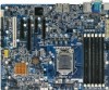
GA-6FXSV2 Motherboard 1.2. Features Summary Form Factor CPU Chipset Memory I/O Control Expansion Slots SATA RAID Controller On-Board VGA On-Board LAN Internal Connector Rear Panel I/O 9.6" x 9.6" Micro ATX size form factor, 6 layers PCB Supports single Intel® LGA1156 (socket H1) processor Support Lynnfield (Quad-core) processor Enhanced Intel SpeedStep Technology (EIST) & Demand Based Switch (DBS) Support Intel Virtualization Technology (VT) Intel® 3420 Chipset 6 x DIMM slots support DDR3 1066/1333 Dual ...
GA-6FXSV2 Motherboard 1.2. Features Summary Form Factor CPU Chipset Memory I/O Control Expansion Slots SATA RAID Controller On-Board VGA On-Board LAN Internal Connector Rear Panel I/O 9.6" x 9.6" Micro ATX size form factor, 6 layers PCB Supports single Intel® LGA1156 (socket H1) processor Support Lynnfield (Quad-core) processor Enhanced Intel SpeedStep Technology (EIST) & Demand Based Switch (DBS) Support Intel Virtualization Technology (VT) Intel® 3420 Chipset 6 x DIMM slots support DDR3 1066/1333 Dual ...
Manual
Page 7
... Monitor BIOS Additional Features GA-6FXSV2 Motherboard 1 x 10/100 LAN port (for server management) Winbond W83627DHG-P controller Enhanced features with CPU Vcore, DDR3 1.5V, VCC3 (3.3V), 12V, 5V, and System Temperature Values viewing CPU/System Fan Revolution Detect CPU shutdown when overheat Phoenix BIOS on 16Mb flash RAM Supports S4, S5 under Windows Operating System AC Recovery Supports Console Redirection Supports 4-pin Fan controller...
... Monitor BIOS Additional Features GA-6FXSV2 Motherboard 1 x 10/100 LAN port (for server management) Winbond W83627DHG-P controller Enhanced features with CPU Vcore, DDR3 1.5V, VCC3 (3.3V), 12V, 5V, and System Temperature Values viewing CPU/System Fan Revolution Detect CPU shutdown when overheat Phoenix BIOS on 16Mb flash RAM Supports S4, S5 under Windows Operating System AC Recovery Supports Console Redirection Supports 4-pin Fan controller...
Manual
Page 8
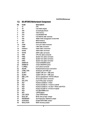
... fan cable connector Channel A DDR3 socket Channel B DDR3 socket front panel connector Keyboard and mouse connectors Serial port and VGA port Gigabit LAN port + USB ports Gigabit LAN port + USB ports Server management 10/100 LAN port 24 pin ATX power connector 8 pin ATX power connector PCIe2.0 (5.0GT/s), x 8 Slot PCIe2.0 (2.5GT/s), x 4 Slot (x1 signal) PCIe2.0 (5.0GT/s), x 16 Slot (**Share with PCI1) PCIe2.0 (2.5GT/s), x 8 Slot (x4 signal) PCI 32bit/33MHz slot CMOS battery Clear CMOS jumper BIOS write protect Jumper Set Supervisor Password jumper Enable SATA RAID jumper BIOS recovery jumper...
... fan cable connector Channel A DDR3 socket Channel B DDR3 socket front panel connector Keyboard and mouse connectors Serial port and VGA port Gigabit LAN port + USB ports Gigabit LAN port + USB ports Server management 10/100 LAN port 24 pin ATX power connector 8 pin ATX power connector PCIe2.0 (5.0GT/s), x 8 Slot PCIe2.0 (2.5GT/s), x 4 Slot (x1 signal) PCIe2.0 (5.0GT/s), x 16 Slot (**Share with PCI1) PCIe2.0 (2.5GT/s), x 8 Slot (x4 signal) PCI 32bit/33MHz slot CMOS battery Clear CMOS jumper BIOS write protect Jumper Set Supervisor Password jumper Enable SATA RAID jumper BIOS recovery jumper...
Manual
Page 10
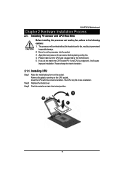
... into the socket. 3. The processor will cause improper installation. Please make sure the CPU type is supported by the motherboard. 5. The CPU only fits in permanent irreparable damage. 2. Apply thermal grease on the CPU socket. Remove the plastic covering on the processor before placing cooling fan. 4. Step 2 Replace the metal cover. Installing CPU Step 1 Raise the metal locking lever on the socket. GA-6FXSV2 Motherboard Chapter 2 Hardware Installation Process 2.1. Please change the...
... into the socket. 3. The processor will cause improper installation. Please make sure the CPU type is supported by the motherboard. 5. The CPU only fits in permanent irreparable damage. 2. Apply thermal grease on the CPU socket. Remove the plastic covering on the processor before placing cooling fan. 4. Step 2 Replace the metal cover. Installing CPU Step 1 Raise the metal locking lever on the socket. GA-6FXSV2 Motherboard Chapter 2 Hardware Installation Process 2.1. Please change the...
Manual
Page 15
Serial Port Connects to the lower port (purple). Gigabit LAN Ports The LAN port provides Internet connection of Gigabit Ethernet with data transfer speeds of 10/100/1000Mbps. Also make sure your OS supports USB controller. USB Port Before you connect your device(s) into USB connector(s), please make sure your device(s) such as USB keyboard, mouse, scanner, zip, speaker...etc. If your OS or device(s) vendors. GA-6FXSV2 Motherboard PS/2 Keyboard and PS/2 Mouse Connector To install a PS/2 port keyboard and mouse, plug the...
Serial Port Connects to the lower port (purple). Gigabit LAN Ports The LAN port provides Internet connection of Gigabit Ethernet with data transfer speeds of 10/100/1000Mbps. Also make sure your OS supports USB controller. USB Port Before you connect your device(s) into USB connector(s), please make sure your device(s) such as USB keyboard, mouse, scanner, zip, speaker...etc. If your OS or device(s) vendors. GA-6FXSV2 Motherboard PS/2 Keyboard and PS/2 Mouse Connector To install a PS/2 port keyboard and mouse, plug the...
Manual
Page 18
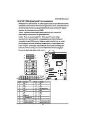
Caution! If a power supply is used (350W or greater). Before connecting the power connector, please make sure that is able to the CPU. The ATX_12V power connector mainly supplies power to support the system voltage requirements. If you use a power supply that is unable to start . GA-6FXSV2 Motherboard 1/2 ) ATX/ATX_CPU (24-pin/ 8-pin ATX power connectors) With the use of the power connector, the power supply can lead to an unstable system or a system that all the components on the motherboard. otherwise, please...
Caution! If a power supply is used (350W or greater). Before connecting the power connector, please make sure that is able to the CPU. The ATX_12V power connector mainly supplies power to support the system voltage requirements. If you use a power supply that is unable to start . GA-6FXSV2 Motherboard 1/2 ) ATX/ATX_CPU (24-pin/ 8-pin ATX power connectors) With the use of the power connector, the power supply can lead to an unstable system or a system that all the components on the motherboard. otherwise, please...
Manual
Page 20
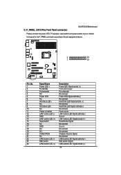
...Power LED Signal anode (+) Front panel power Pin removed No connect Power LED Signal cathode(-) No connect Hard Disk LED Signal anode (+) No connect Hard Disk LED Signal cathode(-) No connect Power button LAN1 active LED Signal cathode(-) Ground LAN1 active LED Signal anode (+) Reset button Signal No connect Ground No connect No connect Chassis intrusion Signal No connect LAN2 active LED Signal cathode(-) NMI switch Signal LAN2 active LED Signal anode (+) 20 6 ) F_PANEL (2X12 Pins Front Panel connector) GA-6FXSV2 Motherboard Please connect the power LED, PC speaker, reset switch and power...
...Power LED Signal anode (+) Front panel power Pin removed No connect Power LED Signal cathode(-) No connect Hard Disk LED Signal anode (+) No connect Hard Disk LED Signal cathode(-) No connect Power button LAN1 active LED Signal cathode(-) Ground LAN1 active LED Signal anode (+) Reset button Signal No connect Ground No connect No connect Chassis intrusion Signal No connect LAN2 active LED Signal cathode(-) NMI switch Signal LAN2 active LED Signal anode (+) 20 6 ) F_PANEL (2X12 Pins Front Panel connector) GA-6FXSV2 Motherboard Please connect the power LED, PC speaker, reset switch and power...
Manual
Page 21
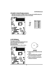
... driver in order to the BIOS setting for 30 second. 3.Re-install the battery. 4.Plug the power cord and turn ON the computer. CAUTION Danger of explosion if battery is incorrectly replaced. Replace only with the same or equivalent type recommended by the manufacturer. Dispose of used batteries according to 300MB/s transfer rate. GA-6FXSV2 Motherboard 6/7/8 ) SATA 0~5 (Serial ATA cable connectors) SATA 3Gb/s can provide up to the manufacturer's instructions...
... driver in order to the BIOS setting for 30 second. 3.Re-install the battery. 4.Plug the power cord and turn ON the computer. CAUTION Danger of explosion if battery is incorrectly replaced. Replace only with the same or equivalent type recommended by the manufacturer. Dispose of used batteries according to 300MB/s transfer rate. GA-6FXSV2 Motherboard 6/7/8 ) SATA 0~5 (Serial ATA cable connectors) SATA 3Gb/s can provide up to the manufacturer's instructions...

Manual
Page 22
... fan cable to the CPU_FAN/SYS_FAN connector to prevent CPU damage or system hanging caused by overheating. FAN4 FAN2 FAN1 FAN3 1 Pin No. 1 2 3 4 Definition GND 12V Sense Control 22 The black connector wire is the ground wire (GND). A red power connector wire indicates a positive connection and requires a +12V power voltage. Most coolers are designed with color-coded power connector wires. GA-6FXSV2 Motherboard 10~13 ) FAN1/2/3/4 (CPU fan/System fan cable connectors) The cooler fan power connector supplies a +12V power voltage via a 3-pin/4-pin(CPU_FAN) power connector...
... fan cable to the CPU_FAN/SYS_FAN connector to prevent CPU damage or system hanging caused by overheating. FAN4 FAN2 FAN1 FAN3 1 Pin No. 1 2 3 4 Definition GND 12V Sense Control 22 The black connector wire is the ground wire (GND). A red power connector wire indicates a positive connection and requires a +12V power voltage. Most coolers are designed with color-coded power connector wires. GA-6FXSV2 Motherboard 10~13 ) FAN1/2/3/4 (CPU fan/System fan cable connectors) The cooler fan power connector supplies a +12V power voltage via a 3-pin/4-pin(CPU_FAN) power connector...
Manual
Page 25
... numeric value or make changes General help, only for Status Page Setup Menu and Option Page Setup Menu Reserved Reserved Reserved Reserved Reserved Reserved Load the Optimized Defaults Save all the CMOS changes, only for Main Menu 25 Exit current page and return to the CMOS SRAM. Chapter 3 BIOS Setup GA-6FXSV Motherboard BIOS (Basic Input and Output System) includes a CMOS SETUP utility which allows user to configure required settings or to activate certain...
... numeric value or make changes General help, only for Status Page Setup Menu and Option Page Setup Menu Reserved Reserved Reserved Reserved Reserved Reserved Load the Optimized Defaults Save all the CMOS changes, only for Main Menu 25 Exit current page and return to the CMOS SRAM. Chapter 3 BIOS Setup GA-6FXSV Motherboard BIOS (Basic Input and Output System) includes a CMOS SETUP utility which allows user to configure required settings or to activate certain...
Manual
Page 26
.... (ex: Auto detect fan and temperature status, automatically configure hard disk parameters.) Power This setup page includes all the items of first boot function features. Exit There are five options in the BIOS Exit Setup menu when somehow the system is displayed at the bottom of Green function features. Security Change, set, or disable password. To exit the Help Window press . Status Page Setup Menu / Option Page Setup Menu Press F1...
.... (ex: Auto detect fan and temperature status, automatically configure hard disk parameters.) Power This setup page includes all the items of first boot function features. Exit There are five options in the BIOS Exit Setup menu when somehow the system is displayed at the bottom of Green function features. Security Change, set, or disable password. To exit the Help Window press . Status Page Setup Menu / Option Page Setup Menu Press F1...
Manual
Page 31
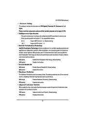
... of CPU Speed, Processor ID ,Processor L2 / L3 Cache. Multiprocessor Specification This option allows user to run multiple operating systems and applications in its cache. Some operating system will be variable depends on the type of today's softwareonly virtual machine solutions. Enabled Adjacent Cache Line Prefetch. (Default setting) Disabled Disables this item, both cache lines that setup menu options will require 1.1 for compatibility reasons. 1.4 Support MPS Version 1.4. (Default setting) 1.1 Support M PS Version 1.1. With virtualization, one...
... of CPU Speed, Processor ID ,Processor L2 / L3 Cache. Multiprocessor Specification This option allows user to run multiple operating systems and applications in its cache. Some operating system will be variable depends on the type of today's softwareonly virtual machine solutions. Enabled Adjacent Cache Line Prefetch. (Default setting) Disabled Disables this item, both cache lines that setup menu options will require 1.1 for compatibility reasons. 1.4 Support MPS Version 1.4. (Default setting) 1.1 Support M PS Version 1.1. With virtualization, one...

Manual
Page 33
... item will pops up sub-menu for configuration. No No changes. (Default setting) Memory Control Settings Manual Select 'Manual" will set to 'No' automatically. Memory Reset Yes Select 'Yes', system will clear the memory error status. Auto Auto configuration. (Default setting) Memory Frequency Select the desire value of the BIOS. Options available: Auto, DDR-3 1066, and DDR-3 1333. 33 Memory Configuration GA-6FXSV Motherboard Figure 2-2: Memory Configuration Base Memory/Extended Memory/Memory Frequency/DIMM Status These category is display-only which is determined by...
... item will pops up sub-menu for configuration. No No changes. (Default setting) Memory Control Settings Manual Select 'Manual" will set to 'No' automatically. Memory Reset Yes Select 'Yes', system will clear the memory error status. Auto Auto configuration. (Default setting) Memory Frequency Select the desire value of the BIOS. Options available: Auto, DDR-3 1066, and DDR-3 1333. 33 Memory Configuration GA-6FXSV Motherboard Figure 2-2: Memory Configuration Base Memory/Extended Memory/Memory Frequency/DIMM Status These category is display-only which is determined by...

Manual
Page 36
PCI Configuration GA-6FXSV Motherboard Figure 2-4: PCI Configuration PCI Slot 1/2/3/4/5 Option ROM Enabled Enable this item to initialize device expansion ROM. (Default setting) Disabled Disable this function. 36 LAN1Option ROM Scan Enabled Enable onboard LAN1 device and initialize device expansion ROM. Disabled Disable this function. (Default setting) Onboard LAN2 Controll Enabled Enable Onboard LAN controller. (Default setting) Disabled Disable this function. Onboard LAN1 Controll Enabled Enable Onboard LAN controller. (Default setting) Disabled Disable this ...
PCI Configuration GA-6FXSV Motherboard Figure 2-4: PCI Configuration PCI Slot 1/2/3/4/5 Option ROM Enabled Enable this item to initialize device expansion ROM. (Default setting) Disabled Disable this function. 36 LAN1Option ROM Scan Enabled Enable onboard LAN1 device and initialize device expansion ROM. Disabled Disable this function. (Default setting) Onboard LAN2 Controll Enabled Enable Onboard LAN controller. (Default setting) Disabled Disable this function. Onboard LAN1 Controll Enabled Enable Onboard LAN controller. (Default setting) Disabled Disable this ...
Manual
Page 38
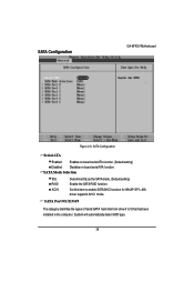
SATA Port 0/1/2/3/4/5 The category identifies the types of Serial SATA hard disk from drive 0 to enable SATA AHCI function for WinXP-SP1+IAA driver supports AHCI mode. Set this item to 5 that has been installed in the computer. System will automatically detect HDD type. 38 SATA Configuration GA-6FXSV Motherboard Figure 2-5: SATA Configuration Serial ATA Enabled Enables on-board serial ATA function. (Default setting) Disabled Disables on-board serial ATA function. SATA Mode Selection IDE RAID ACHI Determine IDE as the SATA mode. (Default setting) Enable the SATA RAID function...
SATA Port 0/1/2/3/4/5 The category identifies the types of Serial SATA hard disk from drive 0 to enable SATA AHCI function for WinXP-SP1+IAA driver supports AHCI mode. Set this item to 5 that has been installed in the computer. System will automatically detect HDD type. 38 SATA Configuration GA-6FXSV Motherboard Figure 2-5: SATA Configuration Serial ATA Enabled Enables on-board serial ATA function. (Default setting) Disabled Disables on-board serial ATA function. SATA Mode Selection IDE RAID ACHI Determine IDE as the SATA mode. (Default setting) Enable the SATA RAID function...

Manual
Page 39
... Transfer Mode. ATAPI Removable: Removable disk drive is installed here. Disabled: The data transfer from and to set all HDD parameters automatically. Users: Set parameters by User. Multi-Sector Transfer This field displays the information of your drive must match with the drive table. LBA Mode This field shows if the device type in the specific IDE channel. 39 Enter the appropriate option based on the outside device casing. TYPE 1-39: Predefined types. Auto: Set parameters automatically. (Default setting) CD-ROM: Use for...
... Transfer Mode. ATAPI Removable: Removable disk drive is installed here. Disabled: The data transfer from and to set all HDD parameters automatically. Users: Set parameters by User. Multi-Sector Transfer This field displays the information of your drive must match with the drive table. LBA Mode This field shows if the device type in the specific IDE channel. 39 Enter the appropriate option based on the outside device casing. TYPE 1-39: Predefined types. Auto: Set parameters automatically. (Default setting) CD-ROM: Use for...

Manual
Page 47
On Enable alarm function to POWER ON system. (Default setting) Off Disable this function. (Default setting) If Resume On Time is set item to Enabled and key in Date/Time to On status: RTC Alarm control select: Manual/Auto Time (0~23) : (0~59) : (0~59) Power On PCI & PCIE Devices Enabled Enable Power On PCI & PCIe Devices. (Default setting) Disabled Disable this function. Power GA-6FXSV Motherboard Figure 3: Power Power On by USB KB/Mouse. (Default setting) Disabled Disable this function. 47 Wake up by USB KB/Mouse Enabled Enable S1 Wake up by RTC...
On Enable alarm function to POWER ON system. (Default setting) Off Disable this function. (Default setting) If Resume On Time is set item to Enabled and key in Date/Time to On status: RTC Alarm control select: Manual/Auto Time (0~23) : (0~59) : (0~59) Power On PCI & PCIE Devices Enabled Enable Power On PCI & PCIe Devices. (Default setting) Disabled Disable this function. Power GA-6FXSV Motherboard Figure 3: Power Power On by USB KB/Mouse. (Default setting) Disabled Disable this function. 47 Wake up by USB KB/Mouse Enabled Enable S1 Wake up by RTC...

Manual
Page 49
... the entered password. GA-6FXSV Motherboard Security About This Section: Security In this section, user can set the virus protection for different level of password securities. Figure 4: Security Set Supervisor Password You can install and change this option. 49 You will clear any previously entered password from the CMOS memory. You may also press to abort the selection and not enter a specified password or press key to disable this options...
... the entered password. GA-6FXSV Motherboard Security About This Section: Security In this section, user can set the virus protection for different level of password securities. Figure 4: Security Set Supervisor Password You can install and change this option. 49 You will clear any previously entered password from the CMOS memory. You may also press to abort the selection and not enter a specified password or press key to disable this options...
Manual
Page 56
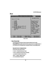
... device fixed or removable. Loads default boot sequence. 56 exclude or include the device to view or configure devices: Up and Down arrows select a device. Specifies the boot sequence from after PhoenixBIOS Post completed. Key used to boot. and moves the device up or down. Enable or disable a device. Boot GA-6FXSV Motherboard Figure 6: Boot Boot Priority Order This field determines which type of device the system attempt to boot from the available devices. If the first device...
... device fixed or removable. Loads default boot sequence. 56 exclude or include the device to view or configure devices: Up and Down arrows select a device. Specifies the boot sequence from after PhoenixBIOS Post completed. Key used to boot. and moves the device up or down. Enable or disable a device. Boot GA-6FXSV Motherboard Figure 6: Boot Boot Priority Order This field determines which type of device the system attempt to boot from the available devices. If the first device...


