
Manual
Page 1
GA-6FXSV2 Xeon Processor Motherboard USER'S Manual Xeon® Processor Motherboard Rev. 1001 * The WEEE marking on the product indicates this product must not be disposed of with user's other household waste and must be handed over to a designated collection point for the recycling of waste electrical and electronic equipment!! * The WEEE marking applies only in European Union's member states.
GA-6FXSV2 Xeon Processor Motherboard USER'S Manual Xeon® Processor Motherboard Rev. 1001 * The WEEE marking on the product indicates this product must not be disposed of with user's other household waste and must be handed over to a designated collection point for the recycling of waste electrical and electronic equipment!! * The WEEE marking applies only in European Union's member states.
Manual
Page 2
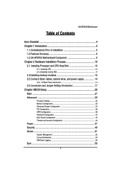
... ...10 2.1.2.Installing Cooling FAN 11 2.2.Installing memory modules 12 2.3.Connect ribbon cables, cabinet wires, and power supply 14 2.3.1. GA-6FXSV2 Motherboard Table of Contents Item Checklist 4 Chapter 1 Introduction 5 1.1.Considerations Prior to Installation 5 1.2.Features Summary 6 1.3.GA-6FXSV2 Motherboard Component 8 Chapter 2 Hardware Installation Process 10 2.1. I/O Back Panel Introduction 14 2.4.Connectors and Jumper Setting Introduction 17 Chapter...
... ...10 2.1.2.Installing Cooling FAN 11 2.2.Installing memory modules 12 2.3.Connect ribbon cables, cabinet wires, and power supply 14 2.3.1. GA-6FXSV2 Motherboard Table of Contents Item Checklist 4 Chapter 1 Introduction 5 1.1.Considerations Prior to Installation 5 1.2.Features Summary 6 1.3.GA-6FXSV2 Motherboard Component 8 Chapter 2 Hardware Installation Process 10 2.1. I/O Back Panel Introduction 14 2.4.Connectors and Jumper Setting Introduction 17 Chapter...
Manual
Page 3
GA-6FXSV2 Motherboard Exit ...57 3
GA-6FXSV2 Motherboard Exit ...57 3
Manual
Page 4
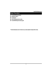
Item Checklist The GA-6FXSV2 motherboard Serial ATA cable x 2 I/O Shield Kit CD for motherboard driver & utility The GA-6FXSV2 quick reference guide GA-6FXSV2 Motherboard * The items listed above are for reference only, and are subject to change without notice. 4
Item Checklist The GA-6FXSV2 motherboard Serial ATA cable x 2 I/O Shield Kit CD for motherboard driver & utility The GA-6FXSV2 quick reference guide GA-6FXSV2 Motherboard * The items listed above are for reference only, and are subject to change without notice. 4
Manual
Page 5
... an uneven surface. 7. Instances of an antistatic pad or within the computer casing. 6. Damage due to be an unofficial Gigabyte product. 5 When handling the motherboard, avoid touching any installation steps or have these items on the motherboard. It is switched... turn off before unplugging the power supply connector from the motherboard. If you are connected. 4. Product determined to improper installation. 4. GA-6FXSV2 Motherboard Chapter 1 Introduction 1.1. Thus, prior to natural disaster, accident or human cause. 2. Please verify that all cables and power connectors...
... an uneven surface. 7. Instances of an antistatic pad or within the computer casing. 6. Damage due to be an unofficial Gigabyte product. 5 When handling the motherboard, avoid touching any installation steps or have these items on the motherboard. It is switched... turn off before unplugging the power supply connector from the motherboard. If you are connected. 4. Product determined to improper installation. 4. GA-6FXSV2 Motherboard Chapter 1 Introduction 1.1. Thus, prior to natural disaster, accident or human cause. 2. Please verify that all cables and power connectors...
Manual
Page 6
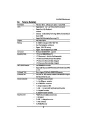
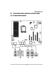
... 4 x System fan cable connector P/S 2 Keyboard and Mouse connectors 1 x Serial port 2 x USB 2.0 dual-port connector 1 x VGA connector 2 x RJ45 LAN ports 6 GA-6FXSV2 Motherboard 1.2.
... 4 x System fan cable connector P/S 2 Keyboard and Mouse connectors 1 x Serial port 2 x USB 2.0 dual-port connector 1 x VGA connector 2 x RJ45 LAN ports 6 GA-6FXSV2 Motherboard 1.2.
Manual
Page 7
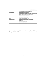
Hardware Monitor BIOS Additional Features GA-6FXSV2 Motherboard 1 x 10/100 LAN port (for server management) Winbond W83627DHG-P controller Enhanced features with CPU Vcore, DDR3 1.5V, VCC3 (3.3V), 12V, 5V, ...
Hardware Monitor BIOS Additional Features GA-6FXSV2 Motherboard 1 x 10/100 LAN port (for server management) Winbond W83627DHG-P controller Enhanced features with CPU Vcore, DDR3 1.5V, VCC3 (3.3V), 12V, 5V, ...
Manual
Page 8
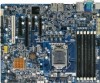
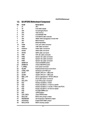
U28 4. SATA0-3 13. DIMM2/4/6 21. BMC_LAN 27. PCI3 32. GA-6FXSV2 Motherboard Component GA-6FXSV2 Motherboard No Code 1. U21 7. COM2_VGA 24. ATX_CPU 29. PCI4 33. BIOS_RVCR Description CPU Intel 3420 chipset ServerEngine Pilot II VGA memory Intel 8578DM PHY Intel ...
U28 4. SATA0-3 13. DIMM2/4/6 21. BMC_LAN 27. PCI3 32. GA-6FXSV2 Motherboard Component GA-6FXSV2 Motherboard No Code 1. U21 7. COM2_VGA 24. ATX_CPU 29. PCI4 33. BIOS_RVCR Description CPU Intel 3420 chipset ServerEngine Pilot II VGA memory Intel 8578DM PHY Intel ...

Manual
Page 9
27 22 28 23 20 19 5 24 25 6 26 7 18 16 29 3 30 31 4 32 33 8 21 10 GA-6FXSV2 Motherboard 15 1 36 17 37 34 38 39 35 9 2 12 11 14 13 9
27 22 28 23 20 19 5 24 25 6 26 7 18 16 29 3 30 31 4 32 33 8 21 10 GA-6FXSV2 Motherboard 15 1 36 17 37 34 38 39 35 9 2 12 11 14 13 9
Manual
Page 10
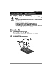
... locking lever on the socket. Step 3 Push the metal lever back into the socket. 3. Please make sure the CPU type is supported by the motherboard. 5. GA-6FXSV2 Motherboard Chapter 2 Hardware Installation Process 2.1. Installing Processor and CPU Heat Sink Before installing the processor and cooling fan, adhere to the following cautions: 1.
... locking lever on the socket. Step 3 Push the metal lever back into the socket. 3. Please make sure the CPU type is supported by the motherboard. 5. GA-6FXSV2 Motherboard Chapter 2 Hardware Installation Process 2.1. Installing Processor and CPU Heat Sink Before installing the processor and cooling fan, adhere to the following cautions: 1.
Manual
Page 11
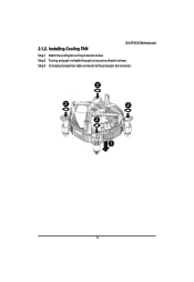
Installing Cooling FAN GA-6FXSV2 Motherboard Step 1 Attach the cooling fan on the processor socket. Step 2 Turning and push vertically the push pin as arrow direction shown. 2.1.2. Step 3 Connect processor fan cable connector to the processor fan connector. 11
Installing Cooling FAN GA-6FXSV2 Motherboard Step 1 Attach the cooling fan on the processor socket. Step 2 Turning and push vertically the push pin as arrow direction shown. 2.1.2. Step 3 Connect processor fan cable connector to the processor fan connector. 11
Manual
Page 12
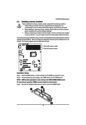
.... Insert the DIMM memory module vertically into the DIMM slot, and push it down. Step 3. Channel B memory socket Channel A memory socket Installation Steps: Step 1. NOTE! GA-6FXSV2 Motherboard 2.2. Memory modules have a foolproof insertion design. Installing memory modules Before installing the memory modules, please comply with each slot. If you wish to use...
.... Insert the DIMM memory module vertically into the DIMM slot, and push it down. Step 3. Channel B memory socket Channel A memory socket Installation Steps: Step 1. NOTE! GA-6FXSV2 Motherboard 2.2. Memory modules have a foolproof insertion design. Installing memory modules Before installing the memory modules, please comply with each slot. If you wish to use...
Manual
Page 13
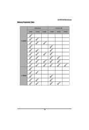
Memory Population Table GA-6FXSV2 Motherboard Channel A DIMM1 DIMM3 DIMM5 Channel B DIMM2 DIMM4 DIMM6 R-DIMM U-DIMM 13
Memory Population Table GA-6FXSV2 Motherboard Channel A DIMM1 DIMM3 DIMM5 Channel B DIMM2 DIMM4 DIMM6 R-DIMM U-DIMM 13
Manual
Page 14
Connect ribbon cables, cabinet wires, and power supply 2.3.1. I/O Back Panel Introduction 14 GA-6FXSV2 Motherboard 2.3.
Connect ribbon cables, cabinet wires, and power supply 2.3.1. I/O Back Panel Introduction 14 GA-6FXSV2 Motherboard 2.3.
Manual
Page 15
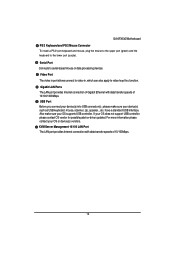
... The LAN port provides Internet connection of Gigabit Ethernet with data transfer speeds of 10/100/1000Mbps. Also make sure your OS supports USB controller. GA-6FXSV2 Motherboard PS/2 Keyboard and PS/2 Mouse Connector To install a PS/2 port keyboard and mouse, plug the mouse to the upper port (green) and the keyboard...
... The LAN port provides Internet connection of Gigabit Ethernet with data transfer speeds of 10/100/1000Mbps. Also make sure your OS supports USB controller. GA-6FXSV2 Motherboard PS/2 Keyboard and PS/2 Mouse Connector To install a PS/2 port keyboard and mouse, plug the mouse to the upper port (green) and the keyboard...
Manual
Page 16
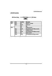
LAN LED Description LED2 (Green/Yellow) GA-6FXSV2 Motherboard LED1 (Green) Name LED1 LED2 Color Green Green Green Green Green Yellow Yellow Condition ON BLINK OFF OFF BLINK ON BLINK ON BLINK Description LAN Link / no Access LAN Access Idle 10Mbps connection Port identification with 10 Mbps connection 100Mbps connection Port identification with 100Mbps connection 1Gbps connection Port identification with 1Gbps connection 16
LAN LED Description LED2 (Green/Yellow) GA-6FXSV2 Motherboard LED1 (Green) Name LED1 LED2 Color Green Green Green Green Green Yellow Yellow Condition ON BLINK OFF OFF BLINK ON BLINK ON BLINK Description LAN Link / no Access LAN Access Idle 10Mbps connection Port identification with 10 Mbps connection 100Mbps connection Port identification with 100Mbps connection 1Gbps connection Port identification with 1Gbps connection 16
Manual
Page 17
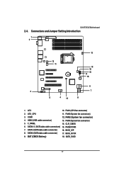
ATX 10. ATX_CPU 11. FAN2 (System fan connector)) 3. SATA4 (SATA data cable connector) 16. BIOS_RVCR 9. Connectors and Jumper Setting Introduction 1 2 13 11 9 10 12 16 15 17 18 6 3 7 5 4 14 8 1. FAN1 (CPU fan connector) 2. FAN3 (System fan connector) 4. SATA5 (SATA data cable connector) 17. SATA_RAID 17 CLR_CMOS 6. COM1 12. F_PANEL 14. BIOS_WP 8. BAT (CMOS Battery) 18. SATA0-3 (SATA data cable connectors) 15. FAN4 (System fan connector) 5. GA-6FXSV2 Motherboard 2.4. USB2 (USB cable connector) 13. PASSWORD 7.
ATX 10. ATX_CPU 11. FAN2 (System fan connector)) 3. SATA4 (SATA data cable connector) 16. BIOS_RVCR 9. Connectors and Jumper Setting Introduction 1 2 13 11 9 10 12 16 15 17 18 6 3 7 5 4 14 8 1. FAN1 (CPU fan connector) 2. FAN3 (System fan connector) 4. SATA5 (SATA data cable connector) 17. SATA_RAID 17 CLR_CMOS 6. COM1 12. F_PANEL 14. BIOS_WP 8. BAT (CMOS Battery) 18. SATA0-3 (SATA data cable connectors) 15. FAN4 (System fan connector) 5. GA-6FXSV2 Motherboard 2.4. USB2 (USB cable connector) 13. PASSWORD 7.
Manual
Page 18
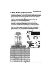
... connect tightly. The ATX_12V power connector mainly supplies power to all components and devices are properly installed. If a power supply is used (350W or greater). GA-6FXSV2 Motherboard 1/2 ) ATX/ATX_CPU (24-pin/ 8-pin ATX power connectors) With the use of the power connector, the power supply can withstand high power consumption be...
... connect tightly. The ATX_12V power connector mainly supplies power to all components and devices are properly installed. If a power supply is used (350W or greater). GA-6FXSV2 Motherboard 1/2 ) ATX/ATX_CPU (24-pin/ 8-pin ATX power connectors) With the use of the power connector, the power supply can withstand high power consumption be...
Manual
Page 19
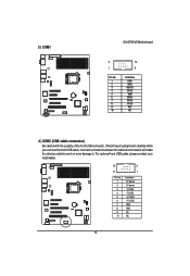
Check the pin assignment carefully while you connect the front USB cable, incorrect connection between the cable and connector will make the device unable to work or even damage it. For optional front USB cable, please contact your local dealer. 10 2 9 1 Pin No. 1 2 3 4 5 6 7 8 9 10 Definition 5V power 5V power -FUSB4 -FUSB5 +FUSB4 +FUSB5 GND GND NC NC 19 3 ) COM1 GA-6FXSV2 Motherboard 2 1 Pin No. 1 2 3 4 5 6 7 8 9 10 10 9 Definition DCDSIN2 SOUT2 DTR2GND DSR2RTS2CTS2RI2NC 4 ) USB2 (USB cable connector) Be careful with the polarity of the front USB connector.
Check the pin assignment carefully while you connect the front USB cable, incorrect connection between the cable and connector will make the device unable to work or even damage it. For optional front USB cable, please contact your local dealer. 10 2 9 1 Pin No. 1 2 3 4 5 6 7 8 9 10 Definition 5V power 5V power -FUSB4 -FUSB5 +FUSB4 +FUSB5 GND GND NC NC 19 3 ) COM1 GA-6FXSV2 Motherboard 2 1 Pin No. 1 2 3 4 5 6 7 8 9 10 10 9 Definition DCDSIN2 SOUT2 DTR2GND DSR2RTS2CTS2RI2NC 4 ) USB2 (USB cable connector) Be careful with the polarity of the front USB connector.
Manual
Page 20
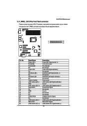
... Chassis intrusion Signal No connect LAN2 active LED Signal cathode(-) NMI switch Signal LAN2 active LED Signal anode (+) 20 6 ) F_PANEL (2X12 Pins Front Panel connector) GA-6FXSV2 Motherboard Please connect the power LED, PC speaker, reset switch and power switch of your chassis front panel to the F_PANEL connector according to the...
... Chassis intrusion Signal No connect LAN2 active LED Signal cathode(-) NMI switch Signal LAN2 active LED Signal anode (+) 20 6 ) F_PANEL (2X12 Pins Front Panel connector) GA-6FXSV2 Motherboard Please connect the power LED, PC speaker, reset switch and power switch of your chassis front panel to the F_PANEL connector according to the...

