Manual
Page 1
G1.Guerrilla LGA1366 socket motherboard for Intel® Core™ i7 processor family User's Manual Rev. 1002 12ME-G1GUERI-1002R
G1.Guerrilla LGA1366 socket motherboard for Intel® Core™ i7 processor family User's Manual Rev. 1002 12ME-G1GUERI-1002R
Manual
Page 7
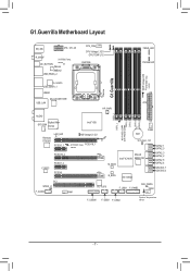
G1.Guerrilla Motherboard Layout KB_MS ATX_12V_2X R_SPDIF SYSTEM2 Temp. sensor VLI VL810 USB_ESATA_1 USB30 Marvell 88E1118R USB_LAN ATX HP_PWR DDR3_2 DDR3_1 NB PHASE LED DDR PHASE LED DDR3_4 DDR3_3 DDR3_6 DDR3_5 AUDIO Bigfoot Killer SYS_FAN E2100 Intel® X58 Renesas D720200 LAN_LED PCIEX1_1 NB Voltage L1/2/3 SYSTEM1 Temp. PCIEX16_1 sensor PCIEX16_2 CODEC PCIEX1_2 PCIEX8 PCI...
G1.Guerrilla Motherboard Layout KB_MS ATX_12V_2X R_SPDIF SYSTEM2 Temp. sensor VLI VL810 USB_ESATA_1 USB30 Marvell 88E1118R USB_LAN ATX HP_PWR DDR3_2 DDR3_1 NB PHASE LED DDR PHASE LED DDR3_4 DDR3_3 DDR3_6 DDR3_5 AUDIO Bigfoot Killer SYS_FAN E2100 Intel® X58 Renesas D720200 LAN_LED PCIEX1_1 NB Voltage L1/2/3 SYSTEM1 Temp. PCIEX16_1 sensor PCIEX16_2 CODEC PCIEX1_2 PCIEX8 PCI...
Manual
Page 8
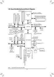
G1.Guerrilla Motherboard Block Diagram 2 PCI Express x8 CPU CLK+/- (133 MHz) LGA1366 CPU DDR3 2200/1333/1066/800 MHz Dual/3 Channel Memory 1 PCI Express x16 1 PCI Express ... E2100 x1 x1 x1 x1 PCI Express Bus JMicron JMB362 PCI Bus 2 SATA 3Gb/s QPI Interface Intel® X58 IOH CLK (133 MHz) PCI Express Bus x2 Marvell 88SE9182 PCIe CLK (100 MHz) 2 SATA 6Gb/s Intel® ICH10R Dual BIOS 6 SATA 3Gb/s 12 USB 2.0/1.1 (Note) CODEC LPC Bus iTE IT8720 PS/2 KB...
G1.Guerrilla Motherboard Block Diagram 2 PCI Express x8 CPU CLK+/- (133 MHz) LGA1366 CPU DDR3 2200/1333/1066/800 MHz Dual/3 Channel Memory 1 PCI Express x16 1 PCI Express ... E2100 x1 x1 x1 x1 PCI Express Bus JMicron JMB362 PCI Bus 2 SATA 3Gb/s QPI Interface Intel® X58 IOH CLK (133 MHz) PCI Express Bus x2 Marvell 88SE9182 PCIe CLK (100 MHz) 2 SATA 6Gb/s Intel® ICH10R Dual BIOS 6 SATA 3Gb/s 12 USB 2.0/1.1 (Note) CODEC LPC Bus iTE IT8720 PS/2 KB...
Manual
Page 15
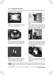
... Apply an even and thin layer of thermal grease on the surface of the motherboard. 1-3-2 Installing the CPU Cooler Follow the steps below to correctly install the CPU cooler on the motherboard. (The following procedure uses Intel® boxed cooler as the picture above shows, the installation is to install.)... Step 3: Place the cooler atop the CPU, aligning the four push pins through the pin holes on the motherboard. Use extreme care when ...
... Apply an even and thin layer of thermal grease on the surface of the motherboard. 1-3-2 Installing the CPU Cooler Follow the steps below to correctly install the CPU cooler on the motherboard. (The following procedure uses Intel® boxed cooler as the picture above shows, the installation is to install.)... Step 3: Place the cooler atop the CPU, aligning the four push pins through the pin holes on the motherboard. Use extreme care when ...

Manual
Page 26
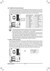
... 13 3.3V 14 GND 15 +5V 16 GND 17 +5V 18 GND 19 Power Good 20 5VSB (stand by the CPU manufacturer when using an Intel Extreme Edition CPU (130W). • To meet expansion requirements, it is recommended that a power supply that does not provide the required power, the result can... power connector possesses a foolproof design. Before connecting the power connector, first make sure the power supply is turned off and all the components on the motherboard.
... 13 3.3V 14 GND 15 +5V 16 GND 17 +5V 18 GND 19 Power Good 20 5VSB (stand by the CPU manufacturer when using an Intel Extreme Edition CPU (130W). • To meet expansion requirements, it is recommended that a power supply that does not provide the required power, the result can... power connector possesses a foolproof design. Before connecting the power connector, first make sure the power supply is turned off and all the components on the motherboard.
Manual
Page 30
... same time. Definition 1 1 SPDIFO 2 GND Hardware Installation - 30 - Definition Pin No. Incorrect connection between the module connector and the motherboard header will make the device unable to activate AC'97 functionality via the audio software in Chapter 51, "Configuring 2/4/5.1/7.1-Channel Audio." •...) for digital audio output from your expansion card. 10) F_AUDIO (Front Panel Audio Header) The front panel audio header supports Intel High Definition audio (HD) and AC'97 audio. Make sure the wire assignments of the module connector match the pin assignments of a...
... same time. Definition 1 1 SPDIFO 2 GND Hardware Installation - 30 - Definition Pin No. Incorrect connection between the module connector and the motherboard header will make the device unable to activate AC'97 functionality via the audio software in Chapter 51, "Configuring 2/4/5.1/7.1-Channel Audio." •...) for digital audio output from your expansion card. 10) F_AUDIO (Front Panel Audio Header) The front panel audio header supports Intel High Definition audio (HD) and AC'97 audio. Make sure the wire assignments of the module connector match the pin assignments of a...
Manual
Page 81
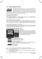
... Click Manual to automatically set eXtreme Hard Drive (X.H.D) under the Integrated Peripherals menu to Enabled to the biggest drive in the Intel Chipset. (Note 2) It is recommended that 's been created earlier, make sure the newly added harddrive has equal or greater... Setting Up a RAID-Ready System Step 1: Configure the system BIOS Enter the system BIOS Setup program, set up all motherboard drivers, including the X.H.D utility. Using GIGABYTE eXtreme Hard Drive (X.H.D) Instructions: (Note 2) Before launching X.H.D, make sure the new drive is added. Unique Features A....
... Click Manual to automatically set eXtreme Hard Drive (X.H.D) under the Integrated Peripherals menu to Enabled to the biggest drive in the Intel Chipset. (Note 2) It is recommended that 's been created earlier, make sure the newly added harddrive has equal or greater... Setting Up a RAID-Ready System Step 1: Configure the system BIOS Enter the system BIOS Setup program, set up all motherboard drivers, including the X.H.D utility. Using GIGABYTE eXtreme Hard Drive (X.H.D) Instructions: (Note 2) Before launching X.H.D, make sure the new drive is added. Unique Features A....
Manual
Page 83
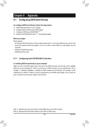
... the rear of the SATA hard drive and the other end to identify the SATA controller for the SATA port. (For example, on the motherboard. C. Configure a RAID array in BIOS Setup. Installing SATA hard drive(s) in your power supply to the hard drive. (Note 1) Skip ...your computer. Appendix Install SATA hard drive(s) in your computer Attach one hard drive. • Windows 7/Vista/XP setup disk. • Motherboard driver disk. 5-1-1 Configuring Intel ICH10R SATA Controllers A. Install the SATA RAID/AHCI driver (Note 2) and operating system. If there is set to create RAID, you ...
... the rear of the SATA hard drive and the other end to identify the SATA controller for the SATA port. (For example, on the motherboard. C. Configure a RAID array in BIOS Setup. Installing SATA hard drive(s) in your power supply to the hard drive. (Note 1) Skip ...your computer. Appendix Install SATA hard drive(s) in your computer Attach one hard drive. • Windows 7/Vista/XP setup disk. • Motherboard driver disk. 5-1-1 Configuring Intel ICH10R SATA Controllers A. Install the SATA RAID/AHCI driver (Note 2) and operating system. If there is set to create RAID, you ...
Manual
Page 103
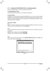
...Step 3: When a screen as the example operating system.) For the Intel ICH10R: As Windows 7 and Vista already include Intel SATA RAID/AHCI driver, you do you want to install Windows?" A. Step 2: Insert the motherboard driver disk and then browse to install separate RAID/AHCI driver during...to install Windows 7/Vista/XP. Installing Windows 7/Vista (The following instructions use Windows 7 as shown in Figure 1 appears, select GIGABYTE GBB36X Controller and click Next to ensure system performance and compatibility. When you install all required drivers from the Windows 7/Vista setup ...
...Step 3: When a screen as the example operating system.) For the Intel ICH10R: As Windows 7 and Vista already include Intel SATA RAID/AHCI driver, you do you want to install Windows?" A. Step 2: Insert the motherboard driver disk and then browse to install separate RAID/AHCI driver during...to install Windows 7/Vista/XP. Installing Windows 7/Vista (The following instructions use Windows 7 as shown in Figure 1 appears, select GIGABYTE GBB36X Controller and click Next to ensure system performance and compatibility. When you install all required drivers from the Windows 7/Vista setup ...
Manual
Page 105
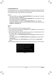
...may not be recognized during the OS installation. Select the controller driver by pressing the corresponding letter from the motherboard driver disk to your floppy disk. Figure 3 - 105 - To install Windows 64-Bit, copy the...Method A: • For the Intel ICH10R, copy all files in the \BootDrv\GSATA\32Bit folder to your floppy disk. Method B: Steps: 1: Use an alternative system and insert the motherboard driver disk. 2: From your optical.... • For the JMicron JMB362, select 3) GIGABYTE GSATA driver for 32bit system for Windows XP 32-bit op- Refer to exit when finished.
...may not be recognized during the OS installation. Select the controller driver by pressing the corresponding letter from the motherboard driver disk to your floppy disk. Figure 3 - 105 - To install Windows 64-Bit, copy the...Method A: • For the Intel ICH10R, copy all files in the \BootDrv\GSATA\32Bit folder to your floppy disk. Method B: Steps: 1: Use an alternative system and insert the motherboard driver disk. 2: From your optical.... • For the JMicron JMB362, select 3) GIGABYTE GSATA driver for 32bit system for Windows XP 32-bit op- Refer to exit when finished.

Manual
Page 109
... been installed from All Programs in Manage Volume. The Status item on the left of the screen displays the rebuild progress. Appendix Then launch the Intel Rapid Storage Technology utility from the motherboard driver disk.
... been installed from All Programs in Manage Volume. The Status item on the left of the screen displays the rebuild progress. Appendix Then launch the Intel Rapid Storage Technology utility from the motherboard driver disk.


