Manual
Page 1
G1.Guerrilla LGA1366 socket motherboard for Intel® Core™ i7 processor family User's Manual Rev. 1002 12ME-G1GUERI-1002R
G1.Guerrilla LGA1366 socket motherboard for Intel® Core™ i7 processor family User's Manual Rev. 1002 12ME-G1GUERI-1002R
Manual
Page 2
Motherboard G1.Guerrilla Feb. 15, 2011 Motherboard G1.Guerrilla Feb. 15, 2011
Motherboard G1.Guerrilla Feb. 15, 2011 Motherboard G1.Guerrilla Feb. 15, 2011
Manual
Page 3
... : "REV: X.X." For product-related information, check on our website at: http://www.gigabyte.com Identifying Your Motherboard Revision The revision number on your motherboard revision before updating motherboard BIOS, drivers, or when looking for technical information. For example, "REV: 1.0" means ..., carefully read the User's Manual. All rights reserved. Check your motherboard looks like this product, GIGABYTE provides the following types of documentations: For quick set-up of GIGABYTE. Copyright © 2011 GIGA-BYTE TECHNOLOGY CO., LTD. Documentation Classifications...
... : "REV: X.X." For product-related information, check on our website at: http://www.gigabyte.com Identifying Your Motherboard Revision The revision number on your motherboard revision before updating motherboard BIOS, drivers, or when looking for technical information. For example, "REV: 1.0" means ..., carefully read the User's Manual. All rights reserved. Check your motherboard looks like this product, GIGABYTE provides the following types of documentations: For quick set-up of GIGABYTE. Copyright © 2011 GIGA-BYTE TECHNOLOGY CO., LTD. Documentation Classifications...
Manual
Page 4
Table of Contents Box Contents...6 Optional Items...6 G1.Guerrilla Motherboard Layout 7 G1.Guerrilla Motherboard Block Diagram 8 Chapter 1 Hardware Installation 9 1-1 Installation Precautions 9 1-2 Product Specifications 10 1-3 Installing the CPU and CPU Cooler 13 1-3-1 Installing the CPU 13 1-3-2 Installing the CPU Cooler ...
Table of Contents Box Contents...6 Optional Items...6 G1.Guerrilla Motherboard Layout 7 G1.Guerrilla Motherboard Block Diagram 8 Chapter 1 Hardware Installation 9 1-1 Installation Precautions 9 1-2 Product Specifications 10 1-3 Installing the CPU and CPU Cooler 13 1-3-1 Installing the CPU 13 1-3-2 Installing the CPU Cooler ...
Manual
Page 6
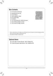
Box Contents G1.Guerrilla motherboard Motherboard driver disk User's Manual Quick Installation Guide Four SATA cables I/O Shield 3.5" Front Panel with 2 USB 3.0/2.0 ports One 2-Way SLI bridge connector One 3-Way SLI bridge connector • The box contents above are subject to change without notice. • The motherboard image is for reference only and the actual items shall depend on the product package you obtain. The box contents are for reference only. Optional Items 2-port USB 2.0 bracket (Part No. 12CR1-1UB030-5*R) 2-port SATA power cable (Part No. 12CF1-2SERPW-0*R) - 6 -
Box Contents G1.Guerrilla motherboard Motherboard driver disk User's Manual Quick Installation Guide Four SATA cables I/O Shield 3.5" Front Panel with 2 USB 3.0/2.0 ports One 2-Way SLI bridge connector One 3-Way SLI bridge connector • The box contents above are subject to change without notice. • The motherboard image is for reference only and the actual items shall depend on the product package you obtain. The box contents are for reference only. Optional Items 2-port USB 2.0 bracket (Part No. 12CR1-1UB030-5*R) 2-port SATA power cable (Part No. 12CF1-2SERPW-0*R) - 6 -
Manual
Page 7
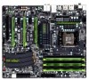
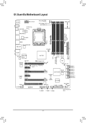
... F_PANEL FAN2 F_USB30 F_USB3 F_USB2 System Temperature sensor - 7 - OC_BUTTON sensor JMicron JMB362 USB_ESATA_2 CPU_FAN CPU Voltage L1/2/3 CPU TEMP L1/2 LGA1366 FREQ. LED PHASE LED G1.Guerrilla DDR Voltage LED SYSTEM3 Temp. G1.Guerrilla Motherboard Layout KB_MS ATX_12V_2X R_SPDIF SYSTEM2 Temp.
... F_PANEL FAN2 F_USB30 F_USB3 F_USB2 System Temperature sensor - 7 - OC_BUTTON sensor JMicron JMB362 USB_ESATA_2 CPU_FAN CPU Voltage L1/2/3 CPU TEMP L1/2 LGA1366 FREQ. LED PHASE LED G1.Guerrilla DDR Voltage LED SYSTEM3 Temp. G1.Guerrilla Motherboard Layout KB_MS ATX_12V_2X R_SPDIF SYSTEM2 Temp.
Manual
Page 8
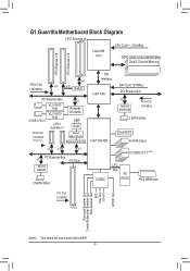
G1.Guerrilla Motherboard Block Diagram 2 PCI Express x8 CPU CLK+/- (133 MHz) LGA1366 CPU DDR3 2200/1333/1066/800 MHz Dual/3 Channel Memory 1 PCI Express x16 1 PCI Express ...
G1.Guerrilla Motherboard Block Diagram 2 PCI Express x8 CPU CLK+/- (133 MHz) LGA1366 CPU DDR3 2200/1333/1066/800 MHz Dual/3 Channel Memory 1 PCI Express x16 1 PCI Express ...
Manual
Page 9
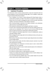
...damage to wear an electrostatic discharge (ESD) wrist strap when handling electronic com- Chapter 1 Hardware Installation 1-1 Installation Precautions The motherboard contains numerous delicate electronic circuits and components which can lead to damage to system components as well as physical harm to the...computer system in a high-temperature environment. • Turning on the computer power during the installation process can become damaged as a motherboard, CPU or memory. Prior to installation, carefully read the user's manual and follow these procedures: • Prior to installation,...
...damage to wear an electrostatic discharge (ESD) wrist strap when handling electronic com- Chapter 1 Hardware Installation 1-1 Installation Precautions The motherboard contains numerous delicate electronic circuits and components which can lead to damage to system components as well as physical harm to the...computer system in a high-temperature environment. • Turning on the computer power during the installation process can become damaged as a motherboard, CPU or memory. Prior to installation, carefully read the user's manual and follow these procedures: • Prior to installation,...
Manual
Page 12
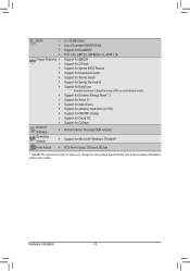
...138;Š Support for Xpress Install ŠŠ Support for Xpress Recovery2 ŠŠ Support for EasyTune * Available functions in EasyTune may differ by motherboard model. ŠŠ Support for Dynamic Energy Saver™ 2 ŠŠ Support for Smart 6™ ŠŠ Support for Auto Green...;Š Support for Microsoft® Windows 7/Vista/XP Form Factor ŠŠ ATX Form Factor; 30.5cm x 26.3cm * GIGABYTE reserves the right to make any changes to the product specifications and product-related information without prior notice. Hardware Installation - 12 -
...138;Š Support for Xpress Install ŠŠ Support for Xpress Recovery2 ŠŠ Support for EasyTune * Available functions in EasyTune may differ by motherboard model. ŠŠ Support for Dynamic Energy Saver™ 2 ŠŠ Support for Smart 6™ ŠŠ Support for Auto Green...;Š Support for Microsoft® Windows 7/Vista/XP Form Factor ŠŠ ATX Form Factor; 30.5cm x 26.3cm * GIGABYTE reserves the right to make any changes to the product specifications and product-related information without prior notice. Hardware Installation - 12 -
Manual
Page 13
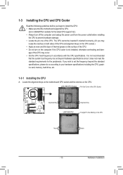
... CPU support list.) • Always turn on the computer if the CPU cooler is not recommended that the motherboard supports the CPU. (Go to GIGABYTE's website for the peripherals. Locate the alignment keys on the motherboard CPU socket and the notches on the CPU Notch Notch - 13 - If you begin to install the...
... CPU support list.) • Always turn on the computer if the CPU cooler is not recommended that the motherboard supports the CPU. (Go to GIGABYTE's website for the peripherals. Locate the alignment keys on the motherboard CPU socket and the notches on the CPU Notch Notch - 13 - If you begin to install the...

Manual
Page 14
... of the CPU socket (or you may align the CPU notches with your finger. Follow the steps below to correctly install the CPU into the motherboard CPU socket. Hardware Installation - 14 - To protect the CPU socket, always replace the protective socket cover when the CPU is properly inserted, replace the load...
... of the CPU socket (or you may align the CPU notches with your finger. Follow the steps below to correctly install the CPU into the motherboard CPU socket. Hardware Installation - 14 - To protect the CPU socket, always replace the protective socket cover when the CPU is properly inserted, replace the load...
Manual
Page 15
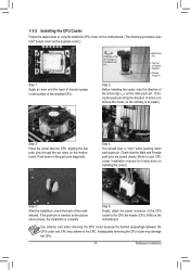
...Step 1: Apply an even and thin layer of thermal grease on the surface of the CPU cooler to correctly install the CPU cooler on the motherboard. (The following procedure uses Intel® boxed cooler as the picture above shows, the installation is to install.) Step 3: Place the cooler ...attach the power connector of the installed CPU. 1-3-2 Installing the CPU Cooler Follow the steps below to the CPU fan header (CPU_FAN) on the motherboard. Check that the Male and Female push pins are joined closely. (Refer to the CPU. Inadequately removing the CPU cooler may adhere to your CPU...
...Step 1: Apply an even and thin layer of thermal grease on the surface of the CPU cooler to correctly install the CPU cooler on the motherboard. (The following procedure uses Intel® boxed cooler as the picture above shows, the installation is to install.) Step 3: Place the cooler ...attach the power connector of the installed CPU. 1-3-2 Installing the CPU Cooler Follow the steps below to the CPU fan header (CPU_FAN) on the motherboard. Check that the Male and Female push pins are joined closely. (Refer to the CPU. Inadequately removing the CPU cooler may adhere to your CPU...
Manual
Page 16
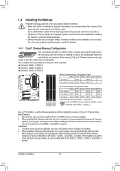
...Channel mode cannot be sure to install it is recommended that memory of the same capacity, brand, speed, and chips be used . (Go to GIGABYTE's website for the latest supported memory speeds and momery moudles.) • Always turn off the computer and unplug the power cord from the power ...before installing the memory to install them in the DDR3_1, DDR3_2, DDR3_3 and DDR3_5 sockets. After the memory is recommended that the motherboard supports the memory. DS/SS - - Dual Channel-1. If you begin to insert the memory, switch the direction. 1-4-1 Dual/3 Channel Memory ...
...Channel mode cannot be sure to install it is recommended that memory of the same capacity, brand, speed, and chips be used . (Go to GIGABYTE's website for the latest supported memory speeds and momery moudles.) • Always turn off the computer and unplug the power cord from the power ...before installing the memory to install them in the DDR3_1, DDR3_2, DDR3_3 and DDR3_5 sockets. After the memory is recommended that the motherboard supports the memory. DS/SS - - Dual Channel-1. If you begin to insert the memory, switch the direction. 1-4-1 Dual/3 Channel Memory ...
Manual
Page 17
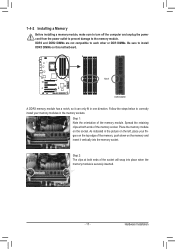
... socket will snap into the memory socket. Step 2: The clips at both ends of the memory module. Hardware Installation Place the memory module on this motherboard.
... socket will snap into the memory socket. Step 2: The clips at both ends of the memory module. Hardware Installation Place the memory module on this motherboard.
Manual
Page 18
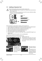
... turn off the computer and unplug the power cord from the power outlet before you begin to install an expansion card: • Make sure the motherboard supports the expansion card. Make sure the metal contacts on your card. Make sure the card is fully inserted into the slot. 4.
... turn off the computer and unplug the power cord from the power outlet before you begin to install an expansion card: • Make sure the motherboard supports the expansion card. Make sure the metal contacts on your card. Make sure the card is fully inserted into the slot. 4.

Manual
Page 19
The 3-Way SLI and 3-Way CrossFireX technologies currently support Windows 7 and Vista operating systems - A CrossFireX/SLI-supported motherboard with sufficient power is selected. One/two CrossFire (Note)/SLI bridge connectors - To Enable CrossFireX Function For 2-Way CrossFireX: After installing the graphics card driver ...
The 3-Way SLI and 3-Way CrossFireX technologies currently support Windows 7 and Vista operating systems - A CrossFireX/SLI-supported motherboard with sufficient power is selected. One/two CrossFire (Note)/SLI bridge connectors - To Enable CrossFireX Function For 2-Way CrossFireX: After installing the graphics card driver ...
Manual
Page 20
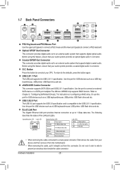
... multiplier.The JMicron JMB362 chip supports RAID function. Hardware Installation - 20 - To return to the USB 2.0/1.1 specification. Do not rock it straight out from the motherboard. • When removing the cable, pull it side to side to connect a PS/2 keyboard. Or use this port for instructions on configuring a RAID array. The...
... multiplier.The JMicron JMB362 chip supports RAID function. Hardware Installation - 20 - To return to the USB 2.0/1.1 specification. Do not rock it straight out from the motherboard. • When removing the cable, pull it side to side to connect a PS/2 keyboard. Or use this port for instructions on configuring a RAID array. The...
Manual
Page 22
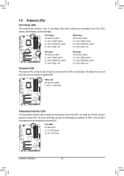
... temperature indicator LEDs indicate the temperature level of lighted LEDs. the red LED is illuminated when the temperature exceeds 80oC. 1-8 Onboard LEDs Overvoltage LEDs This motherboard contains 4 sets of overvoltage LEDs which level the CPU is overclocked. CPU TEMP Off: Below 60oC L1: 61~ 80oC (green) L2: Over 80oC (red) Hardware...
... temperature indicator LEDs indicate the temperature level of lighted LEDs. the red LED is illuminated when the temperature exceeds 80oC. 1-8 Onboard LEDs Overvoltage LEDs This motherboard contains 4 sets of overvoltage LEDs which level the CPU is overclocked. CPU TEMP Off: Below 60oC L1: 61~ 80oC (green) L2: Over 80oC (red) Hardware...
Manual
Page 25
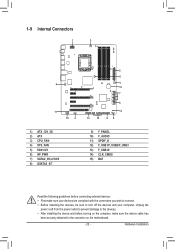
... devices and your devices are compliant with the connectors you wish to connect. • Before installing the devices, be sure to the connector on the motherboard. - 25 - Hardware Installation 1-9 Internal Connectors 1 3 4 11 10 5 2 6 5 15 7 8 14 13 12 95 1) ATX_12V_2X 2) ATX 3) CPU_FAN 4) SYS_FAN 5) FAN1/2/3 6) HP_PWR 7) SATA2_0/1/2/3/4/5 8) GSATA3_6/7 9) F_PANEL 10) F_AUDIO 11) SPDIF_O...
... devices and your devices are compliant with the connectors you wish to connect. • Before installing the devices, be sure to the connector on the motherboard. - 25 - Hardware Installation 1-9 Internal Connectors 1 3 4 11 10 5 2 6 5 15 7 8 14 13 12 95 1) ATX_12V_2X 2) ATX 3) CPU_FAN 4) SYS_FAN 5) FAN1/2/3 6) HP_PWR 7) SATA2_0/1/2/3/4/5 8) GSATA3_6/7 9) F_PANEL 10) F_AUDIO 11) SPDIF_O...

Manual
Page 26
... CPU manufacturer when using an Intel Extreme Edition CPU (130W). • To meet expansion requirements, it is turned off and all the components on the motherboard.
... CPU manufacturer when using an Intel Extreme Edition CPU (130W). • To meet expansion requirements, it is turned off and all the components on the motherboard.


