Manual
Page 3
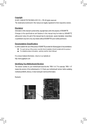
... owners. For product-related information, check on our website at: http://www.gigabyte.com Identifying Your Motherboard Revision The revision number on your motherboard revision before updating motherboard BIOS, drivers, or when looking for technical information. Check your motherboard looks like... with the product. For detailed product information, carefully read the User's Manual. No part of GIGABYTE. The trademarks mentioned in this product, GIGABYTE provides the following types of documentations: For quick set-up of the motherboard is 1.0. Disclaimer Information...
... owners. For product-related information, check on our website at: http://www.gigabyte.com Identifying Your Motherboard Revision The revision number on your motherboard revision before updating motherboard BIOS, drivers, or when looking for technical information. Check your motherboard looks like... with the product. For detailed product information, carefully read the User's Manual. No part of GIGABYTE. The trademarks mentioned in this product, GIGABYTE provides the following types of documentations: For quick set-up of the motherboard is 1.0. Disclaimer Information...
Manual
Page 4
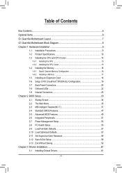
Table of Contents Box Contents...6 Optional Items...6 G1.Guerrilla Motherboard Layout 7 G1.Guerrilla Motherboard Block Diagram 8 Chapter 1 Hardware Installation 9 1-1 Installation Precautions 9 1-2 Product Specifications 10 1-3 Installing the CPU and CPU Cooler ... 1-7 Back Panel Connectors 20 1-8 Onboard LEDs 22 1-9 Internal Connectors 25 Chapter 2 BIOS Setup 33 2-1 Startup Screen 34 2-2 The Main Menu 35 2-3 MB Intelligent Tweaker(M.I.T 37 2-4 Standard CMOS Features 47 2-5 Advanced BIOS Features 49 2-6 Integrated Peripherals 51 2-7 Power Management Setup 53 2-8 PC Health Status...
Table of Contents Box Contents...6 Optional Items...6 G1.Guerrilla Motherboard Layout 7 G1.Guerrilla Motherboard Block Diagram 8 Chapter 1 Hardware Installation 9 1-1 Installation Precautions 9 1-2 Product Specifications 10 1-3 Installing the CPU and CPU Cooler ... 1-7 Back Panel Connectors 20 1-8 Onboard LEDs 22 1-9 Internal Connectors 25 Chapter 2 BIOS Setup 33 2-1 Startup Screen 34 2-2 The Main Menu 35 2-3 MB Intelligent Tweaker(M.I.T 37 2-4 Standard CMOS Features 47 2-5 Advanced BIOS Features 49 2-6 Integrated Peripherals 51 2-7 Power Management Setup 53 2-8 PC Health Status...

Manual
Page 5
... 62 3-4 Contact...63 3-5 System...63 3-6 Download Center 64 3-7 New Utilities...64 Chapter 4 Unique Features 65 4-1 Xpress Recovery2 65 4-2 BIOS Update Utilities 68 4-2-1 Updating the BIOS with the Q-Flash Utility 68 4-2-2 Updating the BIOS with the @BIOS Utility 71 4-3 EasyTune 6...72 4-4 Dynamic Energy Saver™ 2 73 4-5 Q-Share...75 4-6 Smart 6™ ...76 4-7 Auto Green...80 4-8 eXtreme...
... 62 3-4 Contact...63 3-5 System...63 3-6 Download Center 64 3-7 New Utilities...64 Chapter 4 Unique Features 65 4-1 Xpress Recovery2 65 4-2 BIOS Update Utilities 68 4-2-1 Updating the BIOS with the Q-Flash Utility 68 4-2-2 Updating the BIOS with the @BIOS Utility 71 4-3 EasyTune 6...72 4-4 Dynamic Energy Saver™ 2 73 4-5 Q-Share...75 4-6 Smart 6™ ...76 4-7 Auto Green...80 4-8 eXtreme...
Manual
Page 8
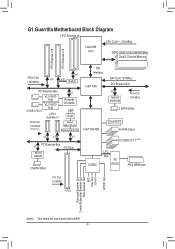
G1.Guerrilla Motherboard Block Diagram 2 PCI Express x8 CPU CLK+/- (133 MHz) LGA1366 CPU DDR3 2200/1333/1066/800 MHz Dual/3 Channel Memory 1 PCI Express x16 1 PCI .../s QPI Interface Intel® X58 IOH CLK (133 MHz) PCI Express Bus x2 Marvell 88SE9182 PCIe CLK (100 MHz) 2 SATA 6Gb/s Intel® ICH10R Dual BIOS 6 SATA 3Gb/s 12 USB 2.0/1.1 (Note) CODEC LPC Bus iTE IT8720 PS/2 KB/Mouse PCI CLK (33 MHz) 1 PCI Surround Speaker Out Center/Subwoofer Speaker Out...
G1.Guerrilla Motherboard Block Diagram 2 PCI Express x8 CPU CLK+/- (133 MHz) LGA1366 CPU DDR3 2200/1333/1066/800 MHz Dual/3 Channel Memory 1 PCI Express x16 1 PCI .../s QPI Interface Intel® X58 IOH CLK (133 MHz) PCI Express Bus x2 Marvell 88SE9182 PCIe CLK (100 MHz) 2 SATA 6Gb/s Intel® ICH10R Dual BIOS 6 SATA 3Gb/s 12 USB 2.0/1.1 (Note) CODEC LPC Bus iTE IT8720 PS/2 KB/Mouse PCI CLK (33 MHz) 1 PCI Surround Speaker Out Center/Subwoofer Speaker Out...
Manual
Page 12
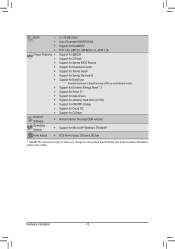
...Mbit flash ŠŠ Use of licensed AWARD BIOS ŠŠ Support for DualBIOS™ ŠŠ PnP 1.0a, DMI 2.0, SM BIOS 2.4, ACPI 1.0b Unique Features ŠŠ Support for @BIOS ŠŠ Support for Q-Flash ŠŠ Support for Xpress BIOS Rescue ŠŠ Support for Download Center ...138; Support for Microsoft® Windows 7/Vista/XP Form Factor ŠŠ ATX Form Factor; 30.5cm x 26.3cm * GIGABYTE reserves the right to make any changes to the product specifications and product-related information without prior notice. Hardware Installation - 12 -
...Mbit flash ŠŠ Use of licensed AWARD BIOS ŠŠ Support for DualBIOS™ ŠŠ PnP 1.0a, DMI 2.0, SM BIOS 2.4, ACPI 1.0b Unique Features ŠŠ Support for @BIOS ŠŠ Support for Q-Flash ŠŠ Support for Xpress BIOS Rescue ŠŠ Support for Download Center ...138; Support for Microsoft® Windows 7/Vista/XP Form Factor ŠŠ ATX Form Factor; 30.5cm x 26.3cm * GIGABYTE reserves the right to make any changes to the product specifications and product-related information without prior notice. Hardware Installation - 12 -
Manual
Page 16
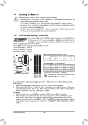
...Two Modules - - DS/SS - - Dual Channel-1. When enabling 3 Channel mode with four memory modules, be used . It is installed, the BIOS will automatically detect the specifications and capacity of the same capacity, brand, speed, and chips be sure to prevent hardware damage. • Memory modules..., speed, and chips be enabled if only one DDR3 memory module is installed. 2. Dual Channel mode cannot be used . (Go to GIGABYTE's website for the latest supported memory speeds and momery moudles.) • Always turn off the computer and unplug the power cord from the ...
...Two Modules - - DS/SS - - Dual Channel-1. When enabling 3 Channel mode with four memory modules, be used . It is installed, the BIOS will automatically detect the specifications and capacity of the same capacity, brand, speed, and chips be sure to prevent hardware damage. • Memory modules..., speed, and chips be enabled if only one DDR3 memory module is installed. 2. Dual Channel mode cannot be used . (Go to GIGABYTE's website for the latest supported memory speeds and momery moudles.) • Always turn off the computer and unplug the power cord from the ...
Manual
Page 18
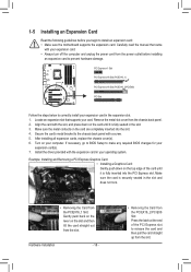
Turn on your expansion card. • Always turn off the computer and unplug the power cord from the slot. If necessary, go to BIOS Setup to the chassis back panel with the slot, and press down on the slot and then lift the card straight out from the chassis ... the metal slot cover from the slot. After installing all expansion cards, replace the chassis cover(s). 6. Secure the card's metal bracket to make any required BIOS changes for your expansion card in the slot and does not rock. • Removing the Card from the PCIEX16_1 Slot: Gently push back on the...
Turn on your expansion card. • Always turn off the computer and unplug the power cord from the slot. If necessary, go to BIOS Setup to the chassis back panel with the slot, and press down on the slot and then lift the card straight out from the chassis ... the metal slot cover from the slot. After installing all expansion cards, replace the chassis cover(s). 6. Secure the card's metal bracket to make any required BIOS changes for your expansion card in the slot and does not rock. • Removing the Card from the PCIEX16_1 Slot: Gently push back on the...
Manual
Page 29
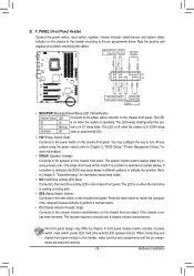
... chassis. The LED is on when the hard drive is in S1 sleep state. When connecting your system using the power switch (refer to Chapter 2, "BIOS Setup," "Power Management Setup," for information about beep codes. • HD (Hard Drive Activity LED, Blue) Connects to the power status indicator on the ...sure the wire assignments and the pin assignments are matched correctly. - 29 - One single short beep will be heard if no problem is detected, the BIOS may configure the way to turn off (S5). • PW (Power Switch, Red): Connects to the reset switch on the chassis front panel.
... chassis. The LED is on when the hard drive is in S1 sleep state. When connecting your system using the power switch (refer to Chapter 2, "BIOS Setup," "Power Management Setup," for information about beep codes. • HD (Hard Drive Activity LED, Blue) Connects to the power status indicator on the ...sure the wire assignments and the pin assignments are matched correctly. - 29 - One single short beep will be heard if no problem is detected, the BIOS may configure the way to turn off (S5). • PW (Power Switch, Red): Connects to the reset switch on the chassis front panel.
Manual
Page 31
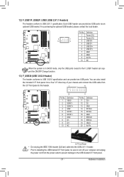
Definition 1 VBUS 11 D2+ 2 SSRX1- 12 D2- 3 SSRX1+ 13 GND 4 GND 14 SSTX2+ 5 SSTX1- 15 SSTX2- 6 SSTX1+ 16 GND 7 GND 17 SSRX2+ DB_PORT BIOS 8 D1- 18 SSRX2- 9 D1+ 19 VBUS 10 NC 20 No Pin TPM w/housing Voltage measurement module(X58A-OC) PW 3.5" Front Panel • Do not plug ...
Definition 1 VBUS 11 D2+ 2 SSRX1- 12 D2- 3 SSRX1+ 13 GND 4 GND 14 SSTX2+ 5 SSTX1- 15 SSTX2- 6 SSTX1+ 16 GND 7 GND 17 SSRX2+ DB_PORT BIOS 8 D1- 18 SSRX2- 9 D1+ 19 VBUS 10 NC 20 No Pin TPM w/housing Voltage measurement module(X58A-OC) PW 3.5" Front Panel • Do not plug ...

Manual
Page 32
... to do so may cause damage to the motherboard. • After system restart, go to BIOS Setup to load factory defaults (select Load Optimized Defaults) or manually configure the BIOS settings (refer to Chapter 2, "BIOS Setup," for one . Danger of the battery (the positive side should face up). •... dealer if you are not able to touch the two pins for 5 seconds.) 3. Gently remove the battery from the jumper. date information and BIOS configurations) and reset the CMOS values to clear the CMOS values (e.g. To clear the CMOS values, place a jumper cap on your computer and...
... to do so may cause damage to the motherboard. • After system restart, go to BIOS Setup to load factory defaults (select Load Optimized Defaults) or manually configure the BIOS settings (refer to Chapter 2, "BIOS Setup," for one . Danger of the battery (the positive side should face up). •... dealer if you are not able to touch the two pins for 5 seconds.) 3. Gently remove the battery from the jumper. date information and BIOS configurations) and reset the CMOS values to clear the CMOS values (e.g. To clear the CMOS values, place a jumper cap on your computer and...
Manual
Page 33
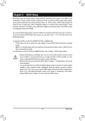
...this chapter or introductions of the battery/ clearing CMOS jumper in system malfunction. • BIOS will emit a beep code during the POST. To upgrade the BIOS, use either the GIGABYTE Q-Flash or @BIOS utility. • Q-Flash allows the user to quickly and easily upgrade or back up... BIOS without entering the operating system. • @BIOS is recommended that you need to) to clear the CMOS values...
...this chapter or introductions of the battery/ clearing CMOS jumper in system malfunction. • BIOS will emit a beep code during the POST. To upgrade the BIOS, use either the GIGABYTE Q-Flash or @BIOS utility. • Q-Flash allows the user to quickly and easily upgrade or back up... BIOS without entering the operating system. • @BIOS is recommended that you need to) to clear the CMOS values...
Manual
Page 34
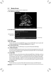
... the first boot device without having to accept. To exit Boot Menu, press . The LOGO Screen (Default) Function Keys B. Motherboard Model BIOS Version G1. BIOS Setup - 34 - In Boot Menu, use the up hard drive data using the driver disk, the key can access Boot Menu again...the device configured in Boot Menu is effective for subsequent access to show the BIOS POST screen at system startup, refer to the instructions on the Full Screen LOGO Show item on BIOS Setup settings. Guerrilla F1h . . . . : BIOS Setup : XpressRecovery2 : Boot Menu : Qflash 01/11/2011-X58-ICH10-7A89QG0SC...
... the first boot device without having to accept. To exit Boot Menu, press . The LOGO Screen (Default) Function Keys B. Motherboard Model BIOS Version G1. BIOS Setup - 34 - In Boot Menu, use the up hard drive data using the driver disk, the key can access Boot Menu again...the device configured in Boot Menu is effective for subsequent access to show the BIOS POST screen at system startup, refer to the instructions on the Full Screen LOGO Show item on BIOS Setup settings. Guerrilla F1h . . . . : BIOS Setup : XpressRecovery2 : Boot Menu : Qflash 01/11/2011-X58-ICH10-7A89QG0SC...
Manual
Page 35
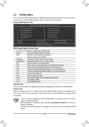
... stable as shown below) appears on the bottom line of the Main Menu. Submenu Help While in a submenu, press to its defaults. • The BIOS Setup menus described in the Item Help block on the right side of a highlighted setup option is in this chapter are for the menu. Help... & Exit Setup Exit Without Saving ESC: Quit F8: Q-Flash Select Item F10: Save & Exit Setup Change CPU's Clock & Voltage F11: Save CMOS to BIOS F12: Load CMOS from BIOS BIOS Setup Program Function Keys Move the selection bar to select an item Execute command or enter the submenu Main Menu: Exit the...
... stable as shown below) appears on the bottom line of the Main Menu. Submenu Help While in a submenu, press to its defaults. • The BIOS Setup menus described in the Item Help block on the right side of a highlighted setup option is in this chapter are for the menu. Help... & Exit Setup Exit Without Saving ESC: Quit F8: Q-Flash Select Item F10: Save & Exit Setup Change CPU's Clock & Voltage F11: Save CMOS to BIOS F12: Load CMOS from BIOS BIOS Setup Program Function Keys Move the selection bar to select an item Execute command or enter the submenu Main Menu: Exit the...
Manual
Page 36
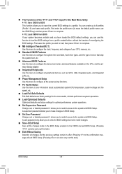
.... MB Intelligent Tweaker(M.I.T.) Use this menu to configure the clock, frequency and voltages of your system becomes unstable and you have loaded the BIOS default settings, you can use the SPACE key) and then press to complete. F12: Load CMOS from a profile created before, without ...to configure the system time and date, hard drive types, and the type of errors that stop the system boot, etc. Advanced BIOS Features Use this menu to configure the device boot order, advanced features available on the CPU, and the primary display adapter. Integrated ...
.... MB Intelligent Tweaker(M.I.T.) Use this menu to configure the clock, frequency and voltages of your system becomes unstable and you have loaded the BIOS default settings, you can use the SPACE key) and then press to complete. F12: Load CMOS from a profile created before, without ...to configure the system time and date, hard drive types, and the type of errors that stop the system boot, etc. Advanced BIOS Features Use this menu to configure the device boot order, advanced features available on the CPU, and the primary display adapter. Integrated ...
Manual
Page 37
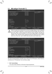
... } Miscellaneous Settings [Press Enter] [Press Enter] [Press Enter] [Press Enter] [Press Enter] Item Help Menu Level BIOS Version BCLK CPU Frequency Memory Frequency Total Memory Size F1h 133.27 MHz 3198.64 MHz 1066.21 MHz 1024 MB CPU Temperature 45oC... } Miscellaneous Settings [Press Enter] [Press Enter] [Press Enter] [Press Enter] [Press Enter] Item Help Menu Level BIOS Version BCLK CPU Frequency Memory Frequency Total Memory Size F1h 133.27 MHz 3198.64 MHz 1066.21 MHz 1024 MB CPU Temperature 45oC...
... } Miscellaneous Settings [Press Enter] [Press Enter] [Press Enter] [Press Enter] [Press Enter] Item Help Menu Level BIOS Version BCLK CPU Frequency Memory Frequency Total Memory Size F1h 133.27 MHz 3198.64 MHz 1066.21 MHz 1024 MB CPU Temperature 45oC... } Miscellaneous Settings [Press Enter] [Press Enter] [Press Enter] [Press Enter] [Press Enter] Item Help Menu Level BIOS Version BCLK CPU Frequency Memory Frequency Total Memory Size F1h 133.27 MHz 3198.64 MHz 1066.21 MHz 1024 MB CPU Temperature 45oC...
Manual
Page 38
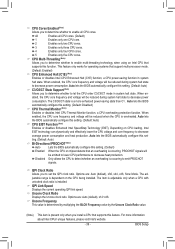
For more information about Intel CPUs' unique features, please visit Intel's website. BIOS Setup - 38 - CPU Frequency Displays the current operating CPU frequency. Advanced CPU Core Features CMOS Setup Utility-Copyright (C) 1984-2011 Award Software Advanced CPU ...: General Help F7: Optimized Defaults CPU Clock Ratio Allows you to determine whether to alter the clock ratio for the installed CPU. Auto lets the BIOS automatically configure this setting. (Default: Auto) (Note 1) This item is present only when you install a memory module that supports this feature.
For more information about Intel CPUs' unique features, please visit Intel's website. BIOS Setup - 38 - CPU Frequency Displays the current operating CPU frequency. Advanced CPU Core Features CMOS Setup Utility-Copyright (C) 1984-2011 Award Software Advanced CPU ...: General Help F7: Optimized Defaults CPU Clock Ratio Allows you to determine whether to alter the clock ratio for the installed CPU. Auto lets the BIOS automatically configure this setting. (Default: Auto) (Note 1) This item is present only when you install a memory module that supports this feature.
Manual
Page 39
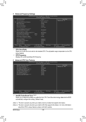
...function, a CPU power-saving function in system halt state. QPI Link Speed Displays the current operating QPI link speed. Auto lets the BIOS automatically configure this setting. (Default: Disabled) CPU Thermal Monitor (Note) Enables or disables Intel CPU Thermal Monitor function, a CPU ...overheating protection function. ting. (Default: Auto) Bi-Directional PROCHOT (Note) Auto Lets the BIOS automatically configure this setting. (Default) Enabled When the CPU or chipset detects that supports this feature. QPI Clock Ratio Allows you ...
...function, a CPU power-saving function in system halt state. QPI Link Speed Displays the current operating QPI link speed. Auto lets the BIOS automatically configure this setting. (Default: Disabled) CPU Thermal Monitor (Note) Enables or disables Intel CPU Thermal Monitor function, a CPU ...overheating protection function. ting. (Default: Auto) Bi-Directional PROCHOT (Note) Auto Lets the BIOS automatically configure this setting. (Default) Enabled When the CPU or chipset detects that supports this feature. QPI Clock Ratio Allows you ...
Manual
Page 40
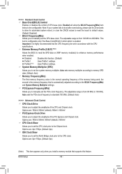
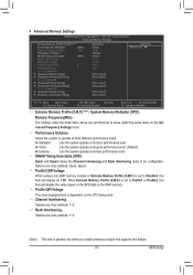
... 150 MHz. CPU Clock Skew Allows you to set the CPU clock prior to the BCLK Frequency(Mhz) and System Memory Multiplier settings. BIOS Setup - 40 - >>>>> Standard Clock Control Base Clock(BCLK) Control Enables or disables the control of the memory being used; Profile2 (... CPU base clock. Disabled Disables this feature. Options are : 700mV, 800mV, 900mV (default), 1000mV. Extreme Memory Profile (X.M.P.) (Note) Allows the BIOS to read the SPD data on XMP memory module(s) to manually set in accordance with the CPU specifications. Options are : 0ps~750ps. (Default:...
... 150 MHz. CPU Clock Skew Allows you to set the CPU clock prior to the BCLK Frequency(Mhz) and System Memory Multiplier settings. BIOS Setup - 40 - >>>>> Standard Clock Control Base Clock(BCLK) Control Enables or disables the control of the memory being used; Profile2 (... CPU base clock. Disabled Disables this feature. Options are : 700mV, 800mV, 900mV (default), 1000mV. Extreme Memory Profile (X.M.P.) (Note) Allows the BIOS to read the SPD data on XMP memory module(s) to manually set in accordance with the CPU specifications. Options are : 0ps~750ps. (Default:...
Manual
Page 41
... Extreme Memory Profile (X.M.P.) is present only when you install a memory module that supports this item will display as 1.5V. Rank Interleaving Options are : Auto (default), 1~6. BIOS Setup DRAM Timing Selectable (SPD) Quick and Expert allows the Channel Interleaving and Rank Interleaving items to Disabled, this item will display the value based...
... Extreme Memory Profile (X.M.P.) is present only when you install a memory module that supports this item will display as 1.5V. Rank Interleaving Options are : Auto (default), 1~6. BIOS Setup DRAM Timing Selectable (SPD) Quick and Expert allows the Channel Interleaving and Rank Interleaving items to Disabled, this item will display the value based...

Manual
Page 42
tRRD Options are : Auto (default), 1~31. tWTP Options are : Auto (default), 1~7. tRP Options are : Auto (default), 1~31. BIOS Setup - 42 - tWTR Options are : Auto (default), 1~15. tWL Options are: Auto (default), 1~10 tRFC Options are : Auto (default), 5~15. x Round Trip Latency 50 Auto ...
tRRD Options are : Auto (default), 1~31. tWTP Options are : Auto (default), 1~7. tRP Options are : Auto (default), 1~31. BIOS Setup - 42 - tWTR Options are : Auto (default), 1~15. tWL Options are: Auto (default), 1~10 tRFC Options are : Auto (default), 5~15. x Round Trip Latency 50 Auto ...


