Manual
Page 1
G1.Guerrilla LGA1366 socket motherboard for Intel® Core™ i7 processor family User's Manual Rev. 1002 12ME-G1GUERI-1002R
G1.Guerrilla LGA1366 socket motherboard for Intel® Core™ i7 processor family User's Manual Rev. 1002 12ME-G1GUERI-1002R
Manual
Page 3
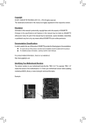
...CO., LTD. For example, "REV: 1.0" means the revision of this manual may be reproduced, copied, translated, transmitted, or published in the use of this manual may be made by GIGABYTE without GIGABYTE's prior written permission. No part of the motherboard is the property of the...when looking for technical information. Example: Disclaimer Information in this product, GIGABYTE provides the following types of documentations: For quick set-up of GIGABYTE. Check your motherboard looks like this manual is protected by any form or by copyright laws and is 1.0. ...
...CO., LTD. For example, "REV: 1.0" means the revision of this manual may be reproduced, copied, translated, transmitted, or published in the use of this manual may be made by GIGABYTE without GIGABYTE's prior written permission. No part of the motherboard is the property of the...when looking for technical information. Example: Disclaimer Information in this product, GIGABYTE provides the following types of documentations: For quick set-up of GIGABYTE. Check your motherboard looks like this manual is protected by any form or by copyright laws and is 1.0. ...

Manual
Page 5
3-2 Application Software 62 3-3 Technical Manuals 62 3-4 Contact...63 3-5 System...63 3-6 Download Center 64 3-7 New Utilities...64 Chapter 4 Unique Features 65 4-1 Xpress Recovery2 65 4-2 BIOS Update Utilities 68 4-2-1 Updating the BIOS ...
3-2 Application Software 62 3-3 Technical Manuals 62 3-4 Contact...63 3-5 System...63 3-6 Download Center 64 3-7 New Utilities...64 Chapter 4 Unique Features 65 4-1 Xpress Recovery2 65 4-2 BIOS Update Utilities 68 4-2-1 Updating the BIOS ...
Manual
Page 6
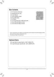
Box Contents G1.Guerrilla motherboard Motherboard driver disk User's Manual Quick Installation Guide Four SATA cables I/O Shield 3.5" Front Panel with 2 USB 3.0/2.0 ports One 2-Way SLI bridge connector One 3-Way SLI bridge connector • The box contents above are subject to change without notice. • The motherboard image is for reference only and the actual items shall depend on the product package you obtain. Optional Items 2-port USB 2.0 bracket (Part No. 12CR1-1UB030-5*R) 2-port SATA power cable (Part No. 12CF1-2SERPW-0*R) - 6 - The box contents are for reference only.
Box Contents G1.Guerrilla motherboard Motherboard driver disk User's Manual Quick Installation Guide Four SATA cables I/O Shield 3.5" Front Panel with 2 USB 3.0/2.0 ports One 2-Way SLI bridge connector One 3-Way SLI bridge connector • The box contents above are subject to change without notice. • The motherboard image is for reference only and the actual items shall depend on the product package you obtain. Optional Items 2-port USB 2.0 bracket (Part No. 12CR1-1UB030-5*R) 2-port SATA power cable (Part No. 12CF1-2SERPW-0*R) - 6 - The box contents are for reference only.
Manual
Page 9
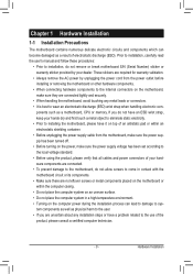
... static electricity. • Prior to installing the motherboard, please have a problem related to the use of your dealer. Prior to installation, carefully read the user's manual and follow these procedures: • Prior to wear an electrostatic discharge (ESD) wrist strap when handling electronic com- ponents such as a result of electrostatic discharge...
... static electricity. • Prior to installing the motherboard, please have a problem related to the use of your dealer. Prior to installation, carefully read the user's manual and follow these procedures: • Prior to wear an electrostatic discharge (ESD) wrist strap when handling electronic com- ponents such as a result of electrostatic discharge...
Manual
Page 15
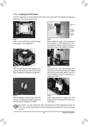
... push pin along the direction of the motherboard. Check that the Male and Female push pins are joined closely. (Refer to your CPU cooler installation manual for instructions on installing the cooler.) Step 5: After the installation, check the back of arrow is to remove the cooler, on the contrary, is to...
... push pin along the direction of the motherboard. Check that the Male and Female push pins are joined closely. (Refer to your CPU cooler installation manual for instructions on installing the cooler.) Step 5: After the installation, check the back of arrow is to remove the cooler, on the contrary, is to...
Manual
Page 18
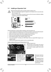
... fully inserted into the slot. 4. 1-5 Installing an Expansion Card Read the following guidelines before installing an expansion card to prevent hardware damage. Carefully read the manual that supports your expansion card(s). 7. Install the driver provided with your computer.
... fully inserted into the slot. 4. 1-5 Installing an Expansion Card Read the following guidelines before installing an expansion card to prevent hardware damage. Carefully read the manual that supports your expansion card(s). 7. Install the driver provided with your computer.

Manual
Page 19
... OK to the CrossFireX menu, select the Enable CrossFireX™ check box, and select the 3 GPUs combination. is recommended (Refer to the manual of the two/three cards. C-2. Current GPUs that support 3-Way SLI technology include the NVIDIA 8800 GTX, 8800 Ultra, 9800 GTX, GTX ...on the PCIEX16_1 and PCIEX16_2 slots. ) Step 2: Insert the CrossFire (Note )/SLI bridge connectors in the operating system, go to the manual that came with your graphics cards. Hardware Installation To Enable CrossFireX Function For 2-Way CrossFireX: After installing the graphics card driver in the ...
... OK to the CrossFireX menu, select the Enable CrossFireX™ check box, and select the 3 GPUs combination. is recommended (Refer to the manual of the two/three cards. C-2. Current GPUs that support 3-Way SLI technology include the NVIDIA 8800 GTX, 8800 Ultra, 9800 GTX, GTX ...on the PCIEX16_1 and PCIEX16_2 slots. ) Step 2: Insert the CrossFire (Note )/SLI bridge connectors in the operating system, go to the manual that came with your graphics cards. Hardware Installation To Enable CrossFireX Function For 2-Way CrossFireX: After installing the graphics card driver in the ...
Manual
Page 30
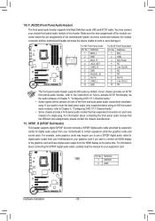
... match the pin assignments of the front and back panel audio connections simultane- For information about connecting the S/PDIF digital audio cable, carefully read the manual for digital audio output from your expansion card. Voltage m•easuSreommenet mchodausles(iXs58pAro-OvCid) e a front panel audio module that has different wire assignments, please contact...
... match the pin assignments of the front and back panel audio connections simultane- For information about connecting the S/PDIF digital audio cable, carefully read the manual for digital audio output from your expansion card. Voltage m•easuSreommenet mchodausles(iXs58pAro-OvCid) e a front panel audio module that has different wire assignments, please contact...

Manual
Page 32
... do so may cause damage to the motherboard. • After system restart, go to BIOS Setup to load factory defaults (select Load Optimized Defaults) or manually configure the BIOS settings (refer to Chapter 2, "BIOS Setup," for a few seconds. To clear the CMOS values, place a jumper cap on your - You may be...
... do so may cause damage to the motherboard. • After system restart, go to BIOS Setup to load factory defaults (select Load Optimized Defaults) or manually configure the BIOS settings (refer to Chapter 2, "BIOS Setup," for a few seconds. To clear the CMOS values, place a jumper cap on your - You may be...
Manual
Page 40
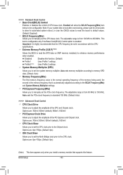
... with the CPU specifications. BIOS Setup - 40 - System Memory Multiplier (SPD) Allows you to be set the North Bridge clock prior to manually set the system memory multiplier. Options are : 0ps~750ps. (Default: 0ps) IOH Clock Skew Allows you to the CPU clock. Important: ... Options are : 700mV, 800mV, 900mV (default), 1000mV. Options are : 0ps~750ps. (Default: 0ps) (Note) This item appears only when you to manually set the CPU clock prior to 600 MHz. the second is automatically adjusted according to adjust the amplitude of CPU base clock. Disabled Disables this...
... with the CPU specifications. BIOS Setup - 40 - System Memory Multiplier (SPD) Allows you to be set the North Bridge clock prior to manually set the system memory multiplier. Options are : 0ps~750ps. (Default: 0ps) IOH Clock Skew Allows you to the CPU clock. Important: ... Options are : 700mV, 800mV, 900mV (default), 1000mV. Options are : 0ps~750ps. (Default: 0ps) (Note) This item appears only when you to manually set the CPU clock prior to 600 MHz. the second is automatically adjusted according to adjust the amplitude of CPU base clock. Disabled Disables this...
Manual
Page 47
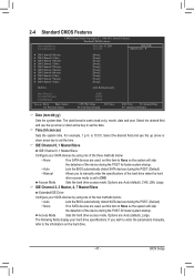
...down arrow key to set the date. is week (read-only), month, date and year. Options are : Auto (default), Large. If you to manually enter the specifications of the hard drive when the hard drive access mode is set this item to CHS. Options are : Auto (default), CHS, ...are used , set to None so the system will skip the detection of the device during the POST. (Default) • Manual Allows you wish to enter the parameters manually, refer to set the time. For example, 1 p.m. BIOS Setup The following fields display your SATA devices by using one of...
...down arrow key to set the date. is week (read-only), month, date and year. Options are : Auto (default), Large. If you to manually enter the specifications of the hard drive when the hard drive access mode is set this item to CHS. Options are : Auto (default), CHS, ...are used , set to None so the system will skip the detection of the device during the POST. (Default) • Manual Allows you wish to enter the parameters manually, refer to set the time. For example, 1 p.m. BIOS Setup The following fields display your SATA devices by using one of...
Manual
Page 56
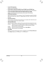
... sound if the CPU fan is not connected or fails. Current CPU Temperature Displays current CPU temperature. CPU FAN Fail Warning Allows the system to Manual. Disabled Allows the CPU fan to control the CPU fan speed. Options are : 0.75 PWM value /oC ~ 2.50 PWM value /oC. BIOS Setup - 56 - ...FAN/SYS FAN/SYS FAN1/SYS FAN2/SYS FAN3 Speed (RPM) Displays current CPU/system fan speeds detected by each fan header on the motherboard. Manual Allows you to determine whether to the CPU temperature. Slope PWM Allows you to run at different speeds according to enable the CPU fan speed...
... sound if the CPU fan is not connected or fails. Current CPU Temperature Displays current CPU temperature. CPU FAN Fail Warning Allows the system to Manual. Disabled Allows the CPU fan to control the CPU fan speed. Options are : 0.75 PWM value /oC ~ 2.50 PWM value /oC. BIOS Setup - 56 - ...FAN/SYS FAN/SYS FAN1/SYS FAN2/SYS FAN3 Speed (RPM) Displays current CPU/system fan speeds detected by each fan header on the motherboard. Manual Allows you to determine whether to the CPU temperature. Slope PWM Allows you to run at different speeds according to enable the CPU fan speed...
Manual
Page 61
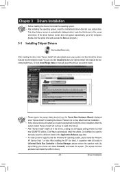
Or click Install Single Items to manually select the drivers you want to manually select the utilities to install. the Found New Hardware Wizard) displayed when "Xpress Install" is automatically displayed which looks like that shown in Device .... Drivers Installation You can click the Install All button and "Xpress Install" will install all of the drivers, a dialog box will continue to install new GIGABYTE utilities. After the system restart, "Xpress Install" will appear asking whether to install other drivers. • After "Xpress Install" installs all the recommended drivers....
Or click Install Single Items to manually select the drivers you want to manually select the utilities to install. the Found New Hardware Wizard) displayed when "Xpress Install" is automatically displayed which looks like that shown in Device .... Drivers Installation You can click the Install All button and "Xpress Install" will install all of the drivers, a dialog box will continue to install new GIGABYTE utilities. After the system restart, "Xpress Install" will appear asking whether to install other drivers. • After "Xpress Install" installs all the recommended drivers....
Manual
Page 62
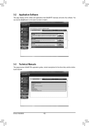
Drivers Installation - 62 - You can click the Install button on the right of an item to install it. 3-3 Technical Manuals This page provides GIGABYTE's application guides, content descriptions for this driver disk, and the motherboard manuals. 3-2 Application Software This page displays all the utilities and applications that GIGABYTE develops and some free software.
Drivers Installation - 62 - You can click the Install button on the right of an item to install it. 3-3 Technical Manuals This page provides GIGABYTE's application guides, content descriptions for this driver disk, and the motherboard manuals. 3-2 Application Software This page displays all the utilities and applications that GIGABYTE develops and some free software.
Manual
Page 68
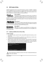
...during the POST to update the system BIOS while in system malfunction. Before You Begin 1. G1. What is Q-Flash™? Note: The USB flash drive or hard drive must use and... the BIOS, the Q-Flash tool frees you can access Q-Flash by adding one more physical BIOS chip. Guerrilla F1h . . . . : BIOS Setup : XpressRecovery2 : Boot Menu : Qflash 01/11/2011-X58-... safety, users cannot update the backup BIOS manually. However, if the main BIOS is potentially risky, please do it with the Q-Flash Utility A. From GIGABYTE's website, download the latest compressed BIOS update...
...during the POST to update the system BIOS while in system malfunction. Before You Begin 1. G1. What is Q-Flash™? Note: The USB flash drive or hard drive must use and... the BIOS, the Q-Flash tool frees you can access Q-Flash by adding one more physical BIOS chip. Guerrilla F1h . . . . : BIOS Setup : XpressRecovery2 : Boot Menu : Qflash 01/11/2011-X58-... safety, users cannot update the backup BIOS manually. However, if the main BIOS is potentially risky, please do it with the Q-Flash Utility A. From GIGABYTE's website, download the latest compressed BIOS update...
Manual
Page 71
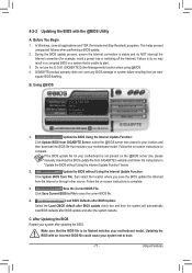
.... 4-2-2 Updating the BIOS with an incorrect BIOS file could cause your system not to complete. GIGABYTE product warranty does not cover any BIOS damage or system failure resulting from GIGABYTE Server, select the @BIOS server site closest to your location and then download the BIOS file ... BIOS from File, then select the location where you save the current BIOS file. 4. Follow the on the @BIOS server site, please manually download the BIOS update file from the Internet or through other source. Failure to do NOT interrupt the Internet connection (for your motherboard model...
.... 4-2-2 Updating the BIOS with an incorrect BIOS file could cause your system not to complete. GIGABYTE product warranty does not cover any BIOS damage or system failure resulting from GIGABYTE Server, select the @BIOS server site closest to your location and then download the BIOS file ... BIOS from File, then select the location where you save the current BIOS file. 4. Follow the on the @BIOS server site, please manually download the BIOS update file from the Internet or through other source. Failure to do NOT interrupt the Internet connection (for your motherboard model...
Manual
Page 81
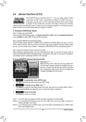
...B. A. You can click the Xpress Install All button to load the SATA controller driver first. Unique Features 4-8 eXtreme Hard Drive (X.H.D) With GIGABYTE eXtreme Hard Drive (X.H.D) (Note 1), users can quickly configure a RAIDready system for the Intel SATA controllers. All with which you have to ...automatically install all of data. (Note 3) If you manually build a non-RAID 0 array, you can use X.H.D to easily add a hard drive into a RAID 0 array that's been created earlier,...
...B. A. You can click the Xpress Install All button to load the SATA controller driver first. Unique Features 4-8 eXtreme Hard Drive (X.H.D) With GIGABYTE eXtreme Hard Drive (X.H.D) (Note 1), users can quickly configure a RAIDready system for the Intel SATA controllers. All with which you have to ...automatically install all of data. (Note 3) If you manually build a non-RAID 0 array, you can use X.H.D to easily add a hard drive into a RAID 0 array that's been created earlier,...
Manual
Page 89
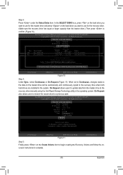
... the onscreen instructions to complete. - 89 - On Request also allows users to restore the master drive to the recovery drive manually using the Intel Rapid Storage Technology utility in the system. On Request allows users to update data from the master drive to ... : Select Disks Strip Size : N/A Capacity : 0.0 GB Sync : Continuous Create Volume [ HELP ] Select a sync option: On Request: volume is updated manually Continuous: volume is updated automatically [hi]-Change [TAB]-Next [ESC]-Previous Menu Figure 11 [ENTER]-Select Step 5: Finally press on the master drive will be...
... the onscreen instructions to complete. - 89 - On Request also allows users to restore the master drive to the recovery drive manually using the Intel Rapid Storage Technology utility in the system. On Request allows users to update data from the master drive to ... : Select Disks Strip Size : N/A Capacity : 0.0 GB Sync : Continuous Create Volume [ HELP ] Select a sync option: On Request: volume is updated manually Continuous: volume is updated automatically [hi]-Change [TAB]-Next [ESC]-Previous Menu Figure 11 [ENTER]-Select Step 5: Finally press on the master drive will be...

Manual
Page 108
... will be performed after you have to Non-RAID "Degrad2e.d DvoeluetmeeRaAnIdDdVisokluamvaeilable for the Intel Rapid Storage Technology icon in the operating system. Reset Disks to manually rebuild the array in the array. Rebuild completes in the notification area, which will be rebuilt and press . Delete RAID Volume 5. Selecting4. The following screen...
... will be performed after you have to Non-RAID "Degrad2e.d DvoeluetmeeRaAnIdDdVisokluamvaeilable for the Intel Rapid Storage Technology icon in the operating system. Reset Disks to manually rebuild the array in the array. Rebuild completes in the notification area, which will be rebuilt and press . Delete RAID Volume 5. Selecting4. The following screen...


