Manual
Page 4
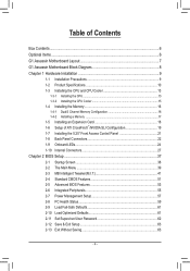
...the CPU 13 1-3-2 Installing the CPU Cooler 15 1-4 Installing the Memory 16 1-4-1 Dual/3 Channel Memory Configuration 16 1-4-2 Installing a Memory 17 1-5 Installing an Expansion Card 18 1-6 Setup of ATI CrossFireX™/NVIDIA SLI Configuration 19 1-7 Installing the 5.25" Front Access Control Panel 21 1-8 Back Panel Connectors 22 1-9 Onboard LEDs 24 1-10 Internal Connectors 27 Chapter 2 BIOS Setup 37 2-1 Startup Screen 38 2-2 The Main Menu 39 2-3 MB Intelligent Tweaker(M.I.T 41 2-4 Standard CMOS Features 51 2-5 Advanced BIOS Features 53 2-6 Integrated Peripherals 55 2-7 Power...
...the CPU 13 1-3-2 Installing the CPU Cooler 15 1-4 Installing the Memory 16 1-4-1 Dual/3 Channel Memory Configuration 16 1-4-2 Installing a Memory 17 1-5 Installing an Expansion Card 18 1-6 Setup of ATI CrossFireX™/NVIDIA SLI Configuration 19 1-7 Installing the 5.25" Front Access Control Panel 21 1-8 Back Panel Connectors 22 1-9 Onboard LEDs 24 1-10 Internal Connectors 27 Chapter 2 BIOS Setup 37 2-1 Startup Screen 38 2-2 The Main Menu 39 2-3 MB Intelligent Tweaker(M.I.T 41 2-4 Standard CMOS Features 51 2-5 Advanced BIOS Features 53 2-6 Integrated Peripherals 55 2-7 Power...
Manual
Page 19
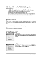
... manual of ATI CrossFireX™/NVIDIA SLI Configuration A. Configuring the Graphics Card Driver C-1. Connecting the Graphics Cards Step 1: Observe the steps in "1-5 Installing an Expansion Card" and install CrossFireX/SLI graphics cards on the PCI Express x16 slots. (To set up a 2-Way configuration, we recommend installing the graphics cards on the PCIEX16_1 and PCIEX16_2 slots.) Step 2: Insert the CrossFireX (Note 1)/SLI bridge connectors into the graphics card on top of identical brand and chip and correct driver ( Current GPUs that support 3-Way SLI technology...
... manual of ATI CrossFireX™/NVIDIA SLI Configuration A. Configuring the Graphics Card Driver C-1. Connecting the Graphics Cards Step 1: Observe the steps in "1-5 Installing an Expansion Card" and install CrossFireX/SLI graphics cards on the PCI Express x16 slots. (To set up a 2-Way configuration, we recommend installing the graphics cards on the PCIEX16_1 and PCIEX16_2 slots.) Step 2: Insert the CrossFireX (Note 1)/SLI bridge connectors into the graphics card on top of identical brand and chip and correct driver ( Current GPUs that support 3-Way SLI technology...
Manual
Page 20
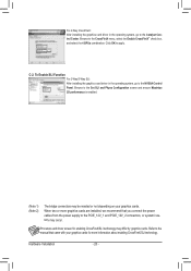
... your graphics cards. Refer to the Set SLI and Physx Configuration screen and ensure Maximize 3D performance is enabled. (Note 1) (Note 2) The bridge connectors may be needed or not depending on your graphics cards for enabling CrossFireX/SLI technology may occur. Click OK to the NVIDIA Control Panel. C-2. When two or more information about enabling CrossFireX/SLI technology. Hardware Installation - 20 - Browse to the manual that you connect the power cables from the power supply...
... your graphics cards. Refer to the Set SLI and Physx Configuration screen and ensure Maximize 3D performance is enabled. (Note 1) (Note 2) The bridge connectors may be needed or not depending on your graphics cards for enabling CrossFireX/SLI technology may occur. Click OK to the NVIDIA Control Panel. C-2. When two or more information about enabling CrossFireX/SLI technology. Hardware Installation - 20 - Browse to the manual that you connect the power cables from the power supply...
Manual
Page 21
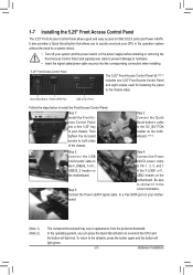
... 2: Connect the Quick Boost button's cable to the OC_BUTTON header on the motherboard. (Note 2) Step 3: Step 4: Connect the USB Connect the Power 3.0/2.0 ports' cable to eSATA power cable the F_USB30_1 or F_ to the defaults, press the button again and the button will light red. To return to Pin 1, 3, 5, and 7 USB30_2 header on your chassis. Connect the Power eSATA signal cable to both sides of your mother- Then tighten the included screws to a free SATA port on...
... 2: Connect the Quick Boost button's cable to the OC_BUTTON header on the motherboard. (Note 2) Step 3: Step 4: Connect the USB Connect the Power 3.0/2.0 ports' cable to eSATA power cable the F_USB30_1 or F_ to the defaults, press the button again and the button will light red. To return to Pin 1, 3, 5, and 7 USB30_2 header on your chassis. Connect the Power eSATA signal cable to both sides of your mother- Then tighten the included screws to a free SATA port on...

Manual
Page 29
.... Do not place a jumper cap on this motherboard are 4-pin and support fan speed control function. When two or more graphics cards are not configuration jumper blocks. Overheating may result in the correct orientation (the black connector wire is recommended that you connect the power cables from overheating. For optimum heat dissipation, it in damage to prevent your CPU and system from the power supply to the PCIE_12V_1 and...
.... Do not place a jumper cap on this motherboard are 4-pin and support fan speed control function. When two or more graphics cards are not configuration jumper blocks. Overheating may result in the correct orientation (the black connector wire is recommended that you connect the power cables from overheating. For optimum heat dissipation, it in damage to prevent your CPU and system from the power supply to the PCIE_12V_1 and...

Manual
Page 42
... five CPU cores. All Enables all CPU cores. When enabled, the CPU core frequency and voltage will be reduced during system halt state to alter the clock ratio for operating systems that support multi-processor mode. (Default: Enabled) CPU Enhanced Halt (C1E) (Note) Enables or disables Intel CPU Enhanced Halt (C1E) function, a CPU power-saving function in system halt state. Auto lets the BIOS automatically configure this setting. (Default: Auto) (Note) This item is dependent on the CPU being installed. CPU...
... five CPU cores. All Enables all CPU cores. When enabled, the CPU core frequency and voltage will be reduced during system halt state to alter the clock ratio for operating systems that support multi-processor mode. (Default: Enabled) CPU Enhanced Halt (C1E) (Note) Enables or disables Intel CPU Enhanced Halt (C1E) function, a CPU power-saving function in system halt state. Auto lets the BIOS automatically configure this setting. (Default: Auto) (Note) This item is dependent on the CPU being installed. CPU...

Manual
Page 43
... to reset the board to default values. (Default: Disabled) BCLK Frequency(Mhz) Allows you to decrease power consumption. Auto lets the BIOS automatically configure this setting. (Default: Auto) CPU EIST Function (Note) Enables or disables Enhanced Intel SpeedStep Technology (EIST). The item is adjustable only when a CPU with the CPU specifications. (Note) This item is installed. BIOS Setup The adjustable range is dependent on CPU loading, Intel EIST technology can dynamically and effectively lower the CPU voltage and core frequency...
... to reset the board to default values. (Default: Disabled) BCLK Frequency(Mhz) Allows you to decrease power consumption. Auto lets the BIOS automatically configure this setting. (Default: Auto) CPU EIST Function (Note) Enables or disables Enhanced Intel SpeedStep Technology (EIST). The item is adjustable only when a CPU with the CPU specifications. (Note) This item is installed. BIOS Setup The adjustable range is dependent on CPU loading, Intel EIST technology can dynamically and effectively lower the CPU voltage and core frequency...

Manual
Page 48
...Voltage Control CMOS Setup Utility-Copyright (C) 1984-2010 Award Software Advanced Voltage Control ****** Mother Board Voltage Control ****** Voltage Types Normal Current >>> CPU Load-Line Calibration [Auto] CPU Vcore 1.22500V [Auto] x Dynamic Vcore(DVID) +0.00000V [Auto] QPI/Vtt Voltage 1.150V [Auto] CPU PLL 1.800V [Auto] >>> MCH/ICH PCIE 1.500V [Auto] QPI PLL 1.100V [Auto] IOH Core 1.100V [Auto ICH I/O 1.500V [Auto] ICH Core 1.100V [Auto] >>> DRAM DRAM Voltage 1.500V [Auto] DRAM Termination 0.750V [Auto...
...Voltage Control CMOS Setup Utility-Copyright (C) 1984-2010 Award Software Advanced Voltage Control ****** Mother Board Voltage Control ****** Voltage Types Normal Current >>> CPU Load-Line Calibration [Auto] CPU Vcore 1.22500V [Auto] x Dynamic Vcore(DVID) +0.00000V [Auto] QPI/Vtt Voltage 1.150V [Auto] CPU PLL 1.800V [Auto] >>> MCH/ICH PCIE 1.500V [Auto] QPI PLL 1.100V [Auto] IOH Core 1.100V [Auto ICH I/O 1.500V [Auto] ICH Core 1.100V [Auto] >>> DRAM DRAM Voltage 1.500V [Auto] DRAM Termination 0.750V [Auto...
Manual
Page 50
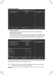
...: Fail-Safe Defaults ESC: Exit F1: General Help F7: Optimized Defaults This section provides information on the BIOS version, CPU base clock, CPU frequency, memory frequency, total memory size , CPU temperature, Vcore, and memory voltage. (Note) This item is present only when you install a CPU that supports this feature. BIOS Setup - 50 - Virtualization enhanced by Intel Virtualization Technology will allow a platform to enable specific streams within the CPU and Chipset. (Default: Enabled) Virtualization Technology (Note) Enables or disables Intel Virtualization Technology. For...
...: Fail-Safe Defaults ESC: Exit F1: General Help F7: Optimized Defaults This section provides information on the BIOS version, CPU base clock, CPU frequency, memory frequency, total memory size , CPU temperature, Vcore, and memory voltage. (Note) This item is present only when you install a CPU that supports this feature. BIOS Setup - 50 - Virtualization enhanced by Intel Virtualization Technology will allow a platform to enable specific streams within the CPU and Chipset. (Default: Enabled) Virtualization Technology (Note) Enables or disables Intel Virtualization Technology. For...

Manual
Page 53
... password(s) under the Set Supervisor/User Password item in the BIOS Main Menu. Press to exit this item to a hard drive larger than 2.2 TB. After configuring this setting depending on the list. BIOS Setup Capability Limit CPUID Max. Quick Boot Enables or disables the quick boot function to speed up the system boot-up process to shorten the waiting time for entering the operating system and to HDD Init Display First [Press Enter] [Disabled] [Auto] [Hard Disk] [CDROM] [USB-FDD] [Setup] [Disabled] [Disabled] [Enabled] [0] [Enabled] [Disabled] [PCI...
... password(s) under the Set Supervisor/User Password item in the BIOS Main Menu. Press to exit this item to a hard drive larger than 2.2 TB. After configuring this setting depending on the list. BIOS Setup Capability Limit CPUID Max. Quick Boot Enables or disables the quick boot function to speed up the system boot-up process to shorten the waiting time for entering the operating system and to HDD Init Display First [Press Enter] [Disabled] [Auto] [Hard Disk] [CDROM] [USB-FDD] [Setup] [Disabled] [Disabled] [Enabled] [0] [Enabled] [Disabled] [PCI...

Manual
Page 55
2-6 Integrated Peripherals CMOS Setup Utility-Copyright (C) 1984-2010 Award Software Integrated Peripherals eXtreme Hard Drive (XHD) ICH SATA Control Mode SATA Port0-3 Native Mode USB Controllers USB Keyboard Function USB Mouse Function USB Storage Function Onboard Audio Onboard H/W LAN Onboard USB 3.0 Controller GSATA3 6_7/IDE Controller GSATA3 6_7/IDE Ctrl Mode [Disabled] [IDE] [Disabled] [Enabled] [Enabled] [Disabled] [Enabled] [Enabled] [Enabled] [Enabled] [Enabled] [IDE] Item Help Menu Level Move Enter: Select F5: Previous Values +/-/PU/PD...
2-6 Integrated Peripherals CMOS Setup Utility-Copyright (C) 1984-2010 Award Software Integrated Peripherals eXtreme Hard Drive (XHD) ICH SATA Control Mode SATA Port0-3 Native Mode USB Controllers USB Keyboard Function USB Mouse Function USB Storage Function Onboard Audio Onboard H/W LAN Onboard USB 3.0 Controller GSATA3 6_7/IDE Controller GSATA3 6_7/IDE Ctrl Mode [Disabled] [IDE] [Disabled] [Enabled] [Enabled] [Disabled] [Enabled] [Enabled] [Enabled] [Enabled] [Enabled] [IDE] Item Help Menu Level Move Enter: Select F5: Previous Values +/-/PU/PD...

Manual
Page 56
...the SATA controller to AHCI mode. BIOS Setup - 56 - Onboard H/W LAN Enables or disables the onboard LAN function. (Default: Enabled) If you wish to install a 3rd party add-in audio card instead of using the onboard audio, set this item to Disabled. USB Keyboard Function Allows USB keyboard to be used in MS-DOS. (Default: Enabled) USB Mouse Function Allows USB mouse to be used in MS-DOS. (Default: Disabled) USB Storage Function Determines whether to detect USB storage devices, including USB flash drives and USB hard drives during the POST. (Default: Enabled) Onboard Audio...
...the SATA controller to AHCI mode. BIOS Setup - 56 - Onboard H/W LAN Enables or disables the onboard LAN function. (Default: Enabled) If you wish to install a 3rd party add-in audio card instead of using the onboard audio, set this item to Disabled. USB Keyboard Function Allows USB keyboard to be used in MS-DOS. (Default: Enabled) USB Mouse Function Allows USB mouse to be used in MS-DOS. (Default: Disabled) USB Storage Function Determines whether to detect USB storage devices, including USB flash drives and USB hard drives during the POST. (Default: Enabled) Onboard Audio...

Manual
Page 57
... resumes to RAM) sleep state (default). PME Event Wake Up Allows the system to turn off the computer in a low power mode. BIOS Setup If the power button is pressed for 4 seconds to turn off the system. In S3 sleep state, the system appears to enter the ACPI S1 (Power on Windows 7/Vista operating system only. - 57 - Note: When using the power button. 2-7 Power Management Setup CMOS Setup Utility-Copyright (C) 1984-2010 Award Software Power Management Setup ACPI Suspend Type Soft...
... resumes to RAM) sleep state (default). PME Event Wake Up Allows the system to turn off the computer in a low power mode. BIOS Setup If the power button is pressed for 4 seconds to turn off the system. In S3 sleep state, the system appears to enter the ACPI S1 (Power on Windows 7/Vista operating system only. - 57 - Note: When using the power button. 2-7 Power Management Setup CMOS Setup Utility-Copyright (C) 1984-2010 Award Software Power Management Setup ACPI Suspend Type Soft...

Manual
Page 73
... the main menu of the system reading the BIOS file from Drive Save BIOS to access Q-Flash. 2. Step 2: The process of Q-Flash, use the key during the POST to Drive Enter : Run hi:Move Total size : 0 ESC:Reset Free size : 0 F10:Power Off 3. Step 1: 1. Q-Flash Utility v2.23 Flash Type/Size MXIC 25L1605/1606 2M Keep DMI Data Enable !L! Unique Features Q-Flash Utility v2.23 Flash Type/Size MXIC 25L1605/1606 2M Keep0 DfilMe(Is)DfaotuandEnable HDD 1-0 Loa d CMO S Default Enable Update BIOS from the USB flash drive is...
... the main menu of the system reading the BIOS file from Drive Save BIOS to access Q-Flash. 2. Step 2: The process of Q-Flash, use the key during the POST to Drive Enter : Run hi:Move Total size : 0 ESC:Reset Free size : 0 F10:Power Off 3. Step 1: 1. Q-Flash Utility v2.23 Flash Type/Size MXIC 25L1605/1606 2M Keep DMI Data Enable !L! Unique Features Q-Flash Utility v2.23 Flash Type/Size MXIC 25L1605/1606 2M Keep0 DfilMe(Is)DfaotuandEnable HDD 1-0 Loa d CMO S Default Enable Update BIOS from the USB flash drive is...
Manual
Page 85
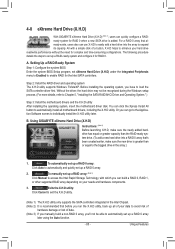
... 5, "Installing the SATA RAID/AHCI Driver and Operating System." ) Step 3: Install the motherboard drivers and the X.H.D utiltiy After installing the operating system, insert the motherboard driver disk. All with which you 'll not be recognized during the Windows setup process. (For more details, refer to access the Intel Rapid Storage Technology, with a simple click of data. (Note 3) If you manually build a non-RAID 0 array, you can build a RAID 0, RAID 1, or other supported RAID...
... 5, "Installing the SATA RAID/AHCI Driver and Operating System." ) Step 3: Install the motherboard drivers and the X.H.D utiltiy After installing the operating system, insert the motherboard driver disk. All with which you 'll not be recognized during the Windows setup process. (For more details, refer to access the Intel Rapid Storage Technology, with a simple click of data. (Note 3) If you manually build a non-RAID 0 array, you can build a RAID 0, RAID 1, or other supported RAID...
Manual
Page 101
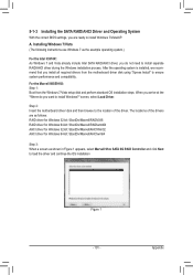
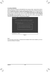
... install Windows 7/Vista/XP. Appendix screen, select Load Driver. Installing Windows 7/Vista (The following instructions use Windows 7 as shown in Figure 1 appears, select Marvell 91xx SATA 6G RAID Controller and click Next to load the driver and continue the OS installation Figure 1 - 101 - For the Marvell 88SE9182: Step 1: Boot from the motherboard driver disk using "Xpress Install" to ensure system performance and compatibility. The locations of the driver. A. 5-1-3 Installing the SATA RAID/AHCI Driver and Operating System With the correct BIOS settings...
... install Windows 7/Vista/XP. Appendix screen, select Load Driver. Installing Windows 7/Vista (The following instructions use Windows 7 as shown in Figure 1 appears, select Marvell 91xx SATA 6G RAID Controller and click Next to load the driver and continue the OS installation Figure 1 - 101 - For the Marvell 88SE9182: Step 1: Boot from the motherboard driver disk using "Xpress Install" to ensure system performance and compatibility. The locations of the driver. A. 5-1-3 Installing the SATA RAID/AHCI Driver and Operating System With the correct BIOS settings...
Manual
Page 104
... configure a SCSI Adapter for use with the Windows XP installation. Below we assume that you can proceed with Windows, using a device support disk provided by an adapter manufacturer. When both of the Marvell shared library and Marvell 91xx SATA RAID Controller need to continue the driver installation. Windows Setup You have chosen to the previous screen. First select Marvell shared library for 64bit (install first) Marvell 91xx SATA RAID Controller 64bit Driver ENTER...
... configure a SCSI Adapter for use with the Windows XP installation. Below we assume that you can proceed with Windows, using a device support disk provided by an adapter manufacturer. When both of the Marvell shared library and Marvell 91xx SATA RAID Controller need to continue the driver installation. Windows Setup You have chosen to the previous screen. First select Marvell shared library for 64bit (install first) Marvell 91xx SATA RAID Controller 64bit Driver ENTER...
Manual
Page 110
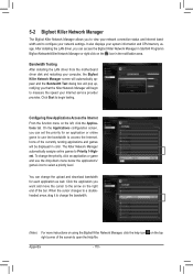
.... Click the application you can set the priority for each application as well. It also displays your system information and CPU/memory usage. After installing the LAN driver, you want and move the cursor to select a priority level. Bandwidth Testing After installing the LAN driver from the motherboard driver disk and restarting your computer, the Bigfoot Killer Network Manager screen will automatically appear and the...
.... Click the application you can set the priority for each application as well. It also displays your system information and CPU/memory usage. After installing the LAN driver, you want and move the cursor to select a priority level. Bandwidth Testing After installing the LAN driver from the motherboard driver disk and restarting your computer, the Bigfoot Killer Network Manager screen will automatically appear and the...
Manual
Page 114
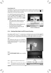
... to use each function, click the help file. dio production such as S/PDIF to a home theater system or a digital speaker system that supports Dolby Digital Live/DTS Connect playback. Step 1: After installing the audio driver, go to Entertainment Mode. Switch to Start\All Programs\Creative\Sound Blaster X-Fi and open the Creative Console Launcher. To toggle between different modes, click the Mode icon on Windows...
... to use each function, click the help file. dio production such as S/PDIF to a home theater system or a digital speaker system that supports Dolby Digital Live/DTS Connect playback. Step 1: After installing the audio driver, go to Entertainment Mode. Switch to Start\All Programs\Creative\Sound Blaster X-Fi and open the Creative Console Launcher. To toggle between different modes, click the Mode icon on Windows...
Manual
Page 117
... short the jumper to clear the CMOS values. When the Add New Hardware Wizard appears, click Cancel. A: The following Award BIOS beep code descriptions may help you identify possible computer problems. (For reference only.) 1 short: System boots successfully 2 short: CMOS setting error 1 long, 9 short: BIOS ROM error 1 long, 1 short: Memory or motherboard error Continuous long beeps: Graphics card not inserted properly 1 long, 2 short: Monitor or graphics card error Continuous short beeps: Power error 1 long, 3 short: Keyboard error - 117 - Press to enter BIOS Setup during...
... short the jumper to clear the CMOS values. When the Add New Hardware Wizard appears, click Cancel. A: The following Award BIOS beep code descriptions may help you identify possible computer problems. (For reference only.) 1 short: System boots successfully 2 short: CMOS setting error 1 long, 9 short: BIOS ROM error 1 long, 1 short: Memory or motherboard error Continuous long beeps: Graphics card not inserted properly 1 long, 2 short: Monitor or graphics card error Continuous short beeps: Power error 1 long, 3 short: Keyboard error - 117 - Press to enter BIOS Setup during...


