User Manual
Page 4
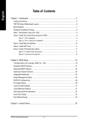
... 2-2: CPU Cooling Fan Installation 9 Step 3: Install Memory Modules 10 Step 4: Install AGP Card ...11 Step 5: Install I/O Peripherals Cables 11 Step 5-1: I/O Back Panel Introduction 11 Step 5-2: Connectors Introduction 12 Chapter 2 BIOS Setup 19 The Main Menu (For example: BIOS Ver. : E8 19 Standard CMOS Features ...21 Advanced BIOS Features ...23 Advanced Chipset Features 24 Integrated Peripherals ...25 Power Management Setup 27 PnP/PCI Configurations ...29 PC Health Status ...30 Load Fail-Safe Defaults ...31 Load Optimized Defaults ...31 Set Supervisor/User Password...
... 2-2: CPU Cooling Fan Installation 9 Step 3: Install Memory Modules 10 Step 4: Install AGP Card ...11 Step 5: Install I/O Peripherals Cables 11 Step 5-1: I/O Back Panel Introduction 11 Step 5-2: Connectors Introduction 12 Chapter 2 BIOS Setup 19 The Main Menu (For example: BIOS Ver. : E8 19 Standard CMOS Features ...21 Advanced BIOS Features ...23 Advanced Chipset Features 24 Integrated Peripherals ...25 Power Management Setup 27 PnP/PCI Configurations ...29 PC Health Status ...30 Load Fail-Safe Defaults ...31 Load Optimized Defaults ...31 Set Supervisor/User Password...
User Manual
Page 5
... devices y 1 Parallel port supporting Normal/EPP/ECP mode y 2 Serial port (COMA, COMB) y 6 USB 2.0/1.1 ports (rear x 2, front x 4 via cable) y 1 front audio connector y 1 IR connector y 1 PS/2 keyboard port y 1 PS/2 mouse port y Onboard RTL8201 chipset (10/100Mbit)* y 1 RJ45 port* y ALC655 codec y Supports 2/ 4/ 6 channel audio y Line Out/ Line In/ Mic In connection y SPDIF In/ Out y CD In/ AUX In/ Game connector y IT8712 y System voltage detection y CPU / System temperature detection y CPU / System fan speed detection y Thermal shutdown function y Use of licensed AWARD BIOS y Supports Q-Flash...
... devices y 1 Parallel port supporting Normal/EPP/ECP mode y 2 Serial port (COMA, COMB) y 6 USB 2.0/1.1 ports (rear x 2, front x 4 via cable) y 1 front audio connector y 1 IR connector y 1 PS/2 keyboard port y 1 PS/2 mouse port y Onboard RTL8201 chipset (10/100Mbit)* y 1 RJ45 port* y ALC655 codec y Supports 2/ 4/ 6 channel audio y Line Out/ Line In/ Mic In connection y SPDIF In/ Out y CD In/ AUX In/ Game connector y IT8712 y System voltage detection y CPU / System temperature detection y CPU / System fan speed detection y Thermal shutdown function y Use of licensed AWARD BIOS y Supports Q-Flash...

User Manual
Page 9
... the system bus frequency be set the frequency beyond hardware specifications since it does not meet the required standards for a cut edge on the center of heat sink paste between your hardware specifications including the CPU, graphics card, memory, hard drive, etc. Make sure the CPU fan is installed on the motherboard. Please set the CPU host frequency in accordance with the following conditions: 1. Insert the CPU into the socket. (Do...
... the system bus frequency be set the frequency beyond hardware specifications since it does not meet the required standards for a cut edge on the center of heat sink paste between your hardware specifications including the CPU, graphics card, memory, hard drive, etc. Make sure the CPU fan is installed on the motherboard. Please set the CPU host frequency in accordance with the following conditions: 1. Insert the CPU into the socket. (Do...

User Manual
Page 11
... your device(s) such as USB keyboard, mouse, scanner, zip, speaker...etc. can be connected to Line In jack. Read the relate AGP card's instruction document before install the AGP card into USB connector(s), please make sure your OS does not support USB controller, please contact OS vendor for possible patch or driver upgrade. Step 5: Install I/O Peripherals Cables Step 5-1: I/O Back Panel Introduction * PS/2 Keyboard and PS/2 Mouse connector To install a PS/2 port keyboard and mouse, plug...
... your device(s) such as USB keyboard, mouse, scanner, zip, speaker...etc. can be connected to Line In jack. Read the relate AGP card's instruction document before install the AGP card into USB connector(s), please make sure your OS does not support USB controller, please contact OS vendor for possible patch or driver upgrade. Step 5: Install I/O Peripherals Cables Step 5-1: I/O Back Panel Introduction * PS/2 Keyboard and PS/2 Mouse connector To install a PS/2 port keyboard and mouse, plug...

User Manual
Page 13
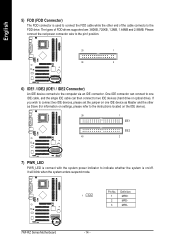
... used (300W or greater). Align the power connector with color-coded power connector wires. Definition 10 20 1 3.3V Pin No. A red power connector wire indicates a positive connection and requires a +12V power voltage. English 1/2) ATX_12V / ATX (Power Connector) With the use a power supply that can withstand high power consumption be used that does not provide the required power, the result can supply enough stable power to all components and devices are designed with its proper location on the motherboard and connect...
... used (300W or greater). Align the power connector with color-coded power connector wires. Definition 10 20 1 3.3V Pin No. A red power connector wire indicates a positive connection and requires a +12V power voltage. English 1/2) ATX_12V / ATX (Power Connector) With the use a power supply that can withstand high power consumption be used that does not provide the required power, the result can supply enough stable power to all components and devices are designed with its proper location on the motherboard and connect...
User Manual
Page 14
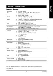
Pin No. It will blink when the system enters suspend mode. If you wish to connect two IDE devices, please set the jumper on one IDE cable, and the single IDE cable can connect to one IDE device as Master and the other end of FDD drives supported are: 360KB, 720KB, 1.2MB, 1.44MB and 2.88MB. Definition 1 1 MPD+ 2 MPD- 3 MPD- 7NF-RZ Series Motherboard - 14 - English 5) FDD (FDD Connector) The FDD connector is on...
Pin No. It will blink when the system enters suspend mode. If you wish to connect two IDE devices, please set the jumper on one IDE cable, and the single IDE cable can connect to one IDE device as Master and the other end of FDD drives supported are: 360KB, 720KB, 1.2MB, 1.44MB and 2.88MB. Definition 1 1 MPD+ 2 MPD- 3 MPD- 7NF-RZ Series Motherboard - 14 - English 5) FDD (FDD Connector) The FDD connector is on...

User Manual
Page 15
... using rear audio connector to use Front Audio connector, you can have front audio connector. RESRES+ NC HD (IDE Hard Disk Active LED) SPK (Speaker Connector) RES (Reset Switch) PW (Power Switch) MSG (Message LED/ Power/ Sleep LED) NC IDE Hard Disk Reset Switch Active LED Pin 1: LED anode(+) Pin 2: LED cathode(-) Pin 1: VCC(+) Pin 2- In order to the pin assignment below. Pin No. PW+ PWSPEAK+ SPEAK- 2 20 1 19 HD+ HD- Hardware Installation Process Message LED/Power/ Sleep LED Power Switch Speaker Connector MSG+ MSG- To find out if the chassis you want to play sound...
... using rear audio connector to use Front Audio connector, you can have front audio connector. RESRES+ NC HD (IDE Hard Disk Active LED) SPK (Speaker Connector) RES (Reset Switch) PW (Power Switch) MSG (Message LED/ Power/ Sleep LED) NC IDE Hard Disk Reset Switch Active LED Pin 1: LED anode(+) Pin 2: LED cathode(-) Pin 1: VCC(+) Pin 2- In order to the pin assignment below. Pin No. PW+ PWSPEAK+ SPEAK- 2 20 1 19 HD+ HD- Hardware Installation Process Message LED/Power/ Sleep LED Power Switch Speaker Connector MSG+ MSG- To find out if the chassis you want to play sound...
User Manual
Page 19
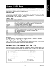
... item. CMOS Setup Utility-Copyright (C) 1984-2004 Award Software ` Standard CMOS Features ` Advanced BIOS Features ` Advanced Chipset Features ` Integrated Peripherals ` Power Management Setup ` PnP/PCI Configurations ` PC Health Status ESC: Quit F8: Q-Flash Load Fail-Safe Defaults Load Optimized Defaults Set Supervisor Password Set User Password Save & Exit Setup Exit Without Saving KLJI: Select Item F10: Save & Exit Setup Time, Date, Hard Disk Type... - 19 - Quit and not save changes into CMOS Status Page Setup Menu and Option Page Setup Menu - Use arrow keys to select...
... item. CMOS Setup Utility-Copyright (C) 1984-2004 Award Software ` Standard CMOS Features ` Advanced BIOS Features ` Advanced Chipset Features ` Integrated Peripherals ` Power Management Setup ` PnP/PCI Configurations ` PC Health Status ESC: Quit F8: Q-Flash Load Fail-Safe Defaults Load Optimized Defaults Set Supervisor Password Set User Password Save & Exit Setup Exit Without Saving KLJI: Select Item F10: Save & Exit Setup Time, Date, Hard Disk Type... - 19 - Quit and not save changes into CMOS Status Page Setup Menu and Option Page Setup Menu - Use arrow keys to select...
User Manual
Page 20
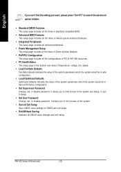
... the system and Setup, or just to Setup. • Set User Password Change, set , or disable password. It allows you to limit access to the system. • Save & Exit Setup Save CMOS value settings to CMOS and exit setup. • Exit Without Saving Abandon all the configurations of PCI & PnP ISA resources. • PC Health Status This setup page is the System auto detect Temperature, voltage, fan, speed. • Load Fail-Safe Defaults Fail-Safe Defaults indicates the...
... the system and Setup, or just to Setup. • Set User Password Change, set , or disable password. It allows you to limit access to the system. • Save & Exit Setup Save CMOS value settings to CMOS and exit setup. • Exit Without Saving Abandon all the configurations of PCI & PnP ISA resources. • PC Health Status This setup page is the System auto detect Temperature, voltage, fan, speed. • Load Fail-Safe Defaults Fail-Safe Defaults indicates the...
User Manual
Page 21
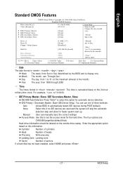
...-time clock. Drive A Drive B Floppy 3 Mode Suport Holt On Base Memory Extended Memory Total Memory KLJI: Move Enter: Select F5: Previous Values [1.44M, 3.5"] [None] [Disabled] [All, But Keyboard] 640K 255M 256M +/-/PU/PD: Value F6: Fail-Save Default F10: Save Jan. You can manually input the correct settings Access Mode Use this if no IDE devices are : CHS/LBA/Large/Auto(default:Auto) Hard drive information should be labeled on the outside drive casing. Manual User can use one...
...-time clock. Drive A Drive B Floppy 3 Mode Suport Holt On Base Memory Extended Memory Total Memory KLJI: Move Enter: Select F5: Previous Values [1.44M, 3.5"] [None] [Disabled] [All, But Keyboard] 640K 255M 256M +/-/PU/PD: Value F6: Fail-Save Default F10: Save Jan. You can manually input the correct settings Access Mode Use this if no IDE devices are : CHS/LBA/Large/Auto(default:Auto) Hard drive information should be labeled on the outside drive casing. Manual User can use one...

User Manual
Page 22
... POST (Power On Self Test) of base (or conventional) memory installed in the system. Both Drive A & B are 3 mode Floppy Drives. it will not stop for a keyboard error; Memory The category is display-only which is typically 512K for systems with 640K or more memory installed on the motherboard, or 640K for a keyboard or disk error; Total Memory This item displays the memory size that may be prompted. English Drive A / Drive B The category identifies the types...
... POST (Power On Self Test) of base (or conventional) memory installed in the system. Both Drive A & B are 3 mode Floppy Drives. it will not stop for a keyboard error; Memory The category is display-only which is typically 512K for systems with 640K or more memory installed on the motherboard, or 640K for a keyboard or disk error; Total Memory This item displays the memory size that may be prompted. English Drive A / Drive B The category identifies the types...
User Manual
Page 23
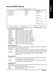
... your boot device priority by ZIP. USB-HDD Select your boot device priority by USB-HDD. Setup The system will boot, but access to Setup will be denied if the correct password is not entered at the prompt. (Default value) Init Display First This feature allows you install an AGP card and a PCI VGA card on board. USB-ZIP Select your boot device priority by USB-ZIP. Disabled BIOS will determine the floppy disk drive installed is 40 or 80 tracks. 360K type...
... your boot device priority by ZIP. USB-HDD Select your boot device priority by USB-HDD. Setup The system will boot, but access to Setup will be denied if the correct password is not entered at the prompt. (Default value) Init Display First This feature allows you install an AGP card and a PCI VGA card on board. USB-ZIP Select your boot device priority by USB-ZIP. Disabled BIOS will determine the floppy disk drive installed is 40 or 80 tracks. 360K type...
User Manual
Page 24
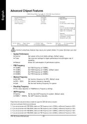
... CMOS Setup Utility-Copyright (C) 1984-2004 Award Software Advanced Chipset Features System Performance FSB Frequency x Memory Frequency Resulting Frequency AGP Frequency [Normal] [133MHz] By SPD 266MHz [Normal] Item Help Menu Level` [Normal] Use the most stable settings. (Default value) Turbo Use overclock settings for system. FSB Frequency 100MHz 133MHz 166MHz 200MHz Set FSB frequency at 200MHz. For power End-User use a processor with higher risk of instability. System Performance Normal Set system at 166MHz. Auto Set the best memory frequency...
... CMOS Setup Utility-Copyright (C) 1984-2004 Award Software Advanced Chipset Features System Performance FSB Frequency x Memory Frequency Resulting Frequency AGP Frequency [Normal] [133MHz] By SPD 266MHz [Normal] Item Help Menu Level` [Normal] Use the most stable settings. (Default value) Turbo Use overclock settings for system. FSB Frequency 100MHz 133MHz 166MHz 200MHz Set FSB frequency at 200MHz. For power End-User use a processor with higher risk of instability. System Performance Normal Set system at 166MHz. Auto Set the best memory frequency...
User Manual
Page 25
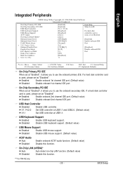
....1 Set USB controller at "Disabled". If a hard disk controller card is used, please set at USB1.1. On-Chip LAN (nVIDIA)* Auto Auto detect on-chip LAN function. (Default value) Disabled Disable this function. English Integrated Peripherals CMOS Setup Utility-Copyright (C) 1984-2004 Award Software Integrated Peripherals On-Chip Primary PCI IDE On-Chip Secondary PCI IDE USB Host Controller USB Keyboard Support USB Mouse Support AC97 Audio On-Chip LAN(nVIDIA)* Onboard Serial Port 1 Onboard Serial Port 2 UART Mode Select x UR2 Duplex Mode Onboard Parallel Port Parallel Port Mode ECP...
....1 Set USB controller at "Disabled". If a hard disk controller card is used, please set at USB1.1. On-Chip LAN (nVIDIA)* Auto Auto detect on-chip LAN function. (Default value) Disabled Disable this function. English Integrated Peripherals CMOS Setup Utility-Copyright (C) 1984-2004 Award Software Integrated Peripherals On-Chip Primary PCI IDE On-Chip Secondary PCI IDE USB Host Controller USB Keyboard Support USB Mouse Support AC97 Audio On-Chip LAN(nVIDIA)* Onboard Serial Port 1 Onboard Serial Port 2 UART Mode Select x UR2 Duplex Mode Onboard Parallel Port Parallel Port Mode ECP...
User Manual
Page 27
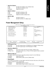
.... Disabled Disable this function. BIOS Setup English Game Port Address 201 Set Game Port Address to 201. (Default value) 209 Set Game Port Address to 5. Disabled Disable this function. (Default value) Midi Port IRQ 5 10 Set Midi Port IRQ to 209. Soft-off by Keyboard x KB Power ON Password AC BACK Function [S1(POS)] [Instant-off] [Enabled] [Enabled] [Disabled] [Disabled] Everyday 0 : 0 : 0 [Disabled] [Disabled] Enter [Soft-Off] Item Help Menu Level` [S1] Set suspend type to Power On Suspend under ACPI OS...
.... Disabled Disable this function. BIOS Setup English Game Port Address 201 Set Game Port Address to 201. (Default value) 209 Set Game Port Address to 5. Disabled Disable this function. (Default value) Midi Port IRQ 5 10 Set Midi Port IRQ to 209. Soft-off by Keyboard x KB Power ON Password AC BACK Function [S1(POS)] [Instant-off] [Enabled] [Enabled] [Disabled] [Disabled] Everyday 0 : 0 : 0 [Disabled] [Disabled] Enter [Soft-Off] Item Help Menu Level` [S1] Set suspend type to Power On Suspend under ACPI OS...

User Manual
Page 29
Auto assign IRQ to PCI 4. (Default value) Set IRQ 3,4,5,7,9,10,11,12,14,15 to PCI 3. Auto assign IRQ to PCI 3. (Default value) Set IRQ 3,4,5,7,9,10,11,12,14,15 to PCI 4. - 29 - BIOS Setup English PnP/PCI Configurations CMOS Setup Utility-Copyright (C) 1984-2004 Award Software PnP/PCI Configurations PCI 1/5 IRQ Assignment PCI 2 IRQ Assignment PCI 3 IRQ Assignment PCI 4 IRQ Assignment [Auto] [Auto] [Auto] [Auto] Item Help Menu Level` KLJI: Move Enter: Select F5: Previous Values PCI 1/5 IRQ Assignment Auto 3,4,5,7,9,10,11,12...
Auto assign IRQ to PCI 4. (Default value) Set IRQ 3,4,5,7,9,10,11,12,14,15 to PCI 3. Auto assign IRQ to PCI 3. (Default value) Set IRQ 3,4,5,7,9,10,11,12,14,15 to PCI 4. - 29 - BIOS Setup English PnP/PCI Configurations CMOS Setup Utility-Copyright (C) 1984-2004 Award Software PnP/PCI Configurations PCI 1/5 IRQ Assignment PCI 2 IRQ Assignment PCI 3 IRQ Assignment PCI 4 IRQ Assignment [Auto] [Auto] [Auto] [Auto] Item Help Menu Level` KLJI: Move Enter: Select F5: Previous Values PCI 1/5 IRQ Assignment Auto 3,4,5,7,9,10,11,12...
User Manual
Page 32
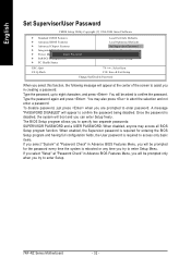
...to enter password. A message "PASSWORD DISABLED" will appear to eight characters, and press . You may access all BIOS Setup program function. If you select "Setup" at the center of the screen to assist you in creating a password. English Set Supervisor/User Password CMOS Setup Utility-Copyright (C) 1984-2004 Award Software ` Standard CMOS Features ` Advanced BIOS Features ` Advanced Chipset Features ` Integrated Peripherals ` Power Management SEentutepr Password: ` PnP/PCI Configurations ` PC Health Status Load Fail-Safe Defaults Load Optimized Defaults Set Supervisor Password...
...to enter password. A message "PASSWORD DISABLED" will appear to eight characters, and press . You may access all BIOS Setup program function. If you select "Setup" at the center of the screen to assist you in creating a password. English Set Supervisor/User Password CMOS Setup Utility-Copyright (C) 1984-2004 Award Software ` Standard CMOS Features ` Advanced BIOS Features ` Advanced Chipset Features ` Integrated Peripherals ` Power Management SEentutepr Password: ` PnP/PCI Configurations ` PC Health Status Load Fail-Safe Defaults Load Optimized Defaults Set Supervisor Password...

User Manual
Page 33
... Setup CMOS Setup Utility-Copyright (C) 1984-2004 Award Software ` Standard CMOS Features ` Advanced BIOS Features ` Advanced Chipset Features ` Integrated Peripherals ` Power Management Setup ` PnP/PCI Configurations ` PC Health Status ESC: Quit F8: Q-Flash Load Fail-Safe Defaults Load Optimized Defaults Set Supervisor Password Set User Password Save to CMOS and EXIT (Y/NS)a?vYe & Exit Setup Exit Without Saving KLJI: Select Item F10: Save & Exit Setup Save Data to CMOS Type "Y" will return to Setup Utility. Type "N" will quit the Setup Utility and save the user setup...
... Setup CMOS Setup Utility-Copyright (C) 1984-2004 Award Software ` Standard CMOS Features ` Advanced BIOS Features ` Advanced Chipset Features ` Integrated Peripherals ` Power Management Setup ` PnP/PCI Configurations ` PC Health Status ESC: Quit F8: Q-Flash Load Fail-Safe Defaults Load Optimized Defaults Set Supervisor Password Set User Password Save to CMOS and EXIT (Y/NS)a?vYe & Exit Setup Exit Without Saving KLJI: Select Item F10: Save & Exit Setup Save Data to CMOS Type "Y" will return to Setup Utility. Type "N" will quit the Setup Utility and save the user setup...

User Manual
Page 35
... your motherboard into your CD-ROM drive, the driver CD-title will restart your system the "Xpress Install" will execute the installation for the system. Click each item to install the driver manually or switch to the to install the drivers automatically. We recommend that need to install other drivers. Install Chipset Drivers This page shows the drivers that you want then click the "GO" button. Massage: Some device drivers will auto start...
... your motherboard into your CD-ROM drive, the driver CD-title will restart your system the "Xpress Install" will execute the installation for the system. Click each item to install the driver manually or switch to the to install the drivers automatically. We recommend that need to install other drivers. Install Chipset Drivers This page shows the drivers that you want then click the "GO" button. Massage: Some device drivers will auto start...

User Manual
Page 36
... remove the question mark and restart the system (System will show a question mark "?" in XP. „ RealTek AC97 Codec Driver Audio driver for RealTek codec chipset. „ nVIDIA USB 2.0 Driver Information USB 2.0 driver information for XP. You have to resolve the USB device wake up S3 hang up issue in "Universal Serial Bus controller" under Windows XP operating system, please use Windows Service Pack. For USB2.0 driver support under "Device Manager". English Driver install...
... remove the question mark and restart the system (System will show a question mark "?" in XP. „ RealTek AC97 Codec Driver Audio driver for RealTek codec chipset. „ nVIDIA USB 2.0 Driver Information USB 2.0 driver information for XP. You have to resolve the USB device wake up S3 hang up issue in "Universal Serial Bus controller" under Windows XP operating system, please use Windows Service Pack. For USB2.0 driver support under "Device Manager". English Driver install...


