Installation Instructions
Page 1
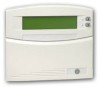
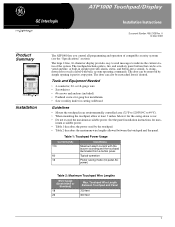
... the panel installation instructions for the swing-down cover. • Do not exceed the maximum available power. Table 1: Touchpad Power Usage Current (mA) 110 60 12 Conditions Maximum alarm current with basic system operating commands. A built-in an environmentally controlled area (32°F to 120°F/0°C to indicate the current status of compatible security systems (see the "Specifications" section). Tools and Equipment Needed •...
... the panel installation instructions for the swing-down cover. • Do not exceed the maximum available power. Table 1: Touchpad Power Usage Current (mA) 110 60 12 Conditions Maximum alarm current with basic system operating commands. A built-in an environmentally controlled area (32°F to 120°F/0°C to indicate the current status of compatible security systems (see the "Specifications" section). Tools and Equipment Needed •...
Installation Instructions
Page 2
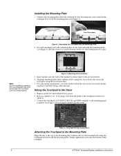
... of the touchpad. 2 ATP1000 Touchpad/Display Installation Instructions Wiring the Touchpad to pull the wiring cable through. For wall-mount installations, cut a hole in the wall in the wire access area of the mounting plate with the wall or gang box screw holes and secure the back plate using the screws provided. 5. ing plate to the Panel 1. Installing the Mounting Plate 1. Separate the mounting plate from the touchpad by first...
... of the touchpad. 2 ATP1000 Touchpad/Display Installation Instructions Wiring the Touchpad to pull the wiring cable through. For wall-mount installations, cut a hole in the wall in the wire access area of the mounting plate with the wall or gang box screw holes and secure the back plate using the screws provided. 5. ing plate to the Panel 1. Installing the Mounting Plate 1. Separate the mounting plate from the touchpad by first...
Installation Instructions
Page 3
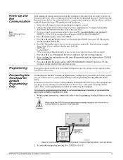
... newly installed touchpad (such as key beeps) see Figure 4). ! For installations that all wiring between the touchpad and the panel. To connect a programming touchpad to the Programming Touchpad Header on the backside. ATP1000 Touchpad/Display Installation Instructions 3 Connect the panel battery and restore AC power. Press ƒ and the display shows SECURITY. 5. The touchpad should show SCANNING BUS DEVICES, then display date and time. 3. With the panel powered up , the panel scans the bus for System Programming Only After making all bus device addresses until...
... newly installed touchpad (such as key beeps) see Figure 4). ! For installations that all wiring between the touchpad and the panel. To connect a programming touchpad to the Programming Touchpad Header on the backside. ATP1000 Touchpad/Display Installation Instructions 3 Connect the panel battery and restore AC power. Press ƒ and the display shows SECURITY. 5. The touchpad should show SCANNING BUS DEVICES, then display date and time. 3. With the panel powered up , the panel scans the bus for System Programming Only After making all bus device addresses until...
Installation Instructions
Page 4
... the programming touchpad. Press ƒ. Test the touchpad by arming/disarming the system, activating the touchpad panics, bypassing sensors, and by pressing 9 + user, partition, or system master CODE. Refer to a Concord panel with software versions 1.0-1.6 display USER CODES.) 2. The display shows SYSTEM MENU, then TIME AND DATE (Concord panels with software versions 1.0-1.6: 1. Enter configuration mode by pressing 8 + installer/dealer CODE + 0 + 0 and program the panel using the panel Installation Instructions. 4. To connect a programming touchpad to the panel User's Manual for...
... the programming touchpad. Press ƒ. Test the touchpad by arming/disarming the system, activating the touchpad panics, bypassing sensors, and by pressing 9 + user, partition, or system master CODE. Refer to a Concord panel with software versions 1.0-1.6 display USER CODES.) 2. The display shows SYSTEM MENU, then TIME AND DATE (Concord panels with software versions 1.0-1.6: 1. Enter configuration mode by pressing 8 + installer/dealer CODE + 0 + 0 and program the panel using the panel Installation Instructions. 4. To connect a programming touchpad to the panel User's Manual for...
Installation Instructions
Page 5
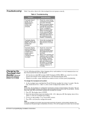
... electrical outlet controlled by the panel, communication between bus devices and the panel: • All bus devices with the procedure. Troubleshooting Table 3 describes what to commands from the configuration mode. Touchpad display shows a flashing *, indicating a trouble condition and system doesn't respond to do if the touchpad does not operate correctly. If necessary, change the touchpad unit number: 1. The bus failure will clear after successfully changing the touchpad unit number. 2. Check for correct bus wiring connections (green and white wires...
... electrical outlet controlled by the panel, communication between bus devices and the panel: • All bus devices with the procedure. Troubleshooting Table 3 describes what to commands from the configuration mode. Touchpad display shows a flashing *, indicating a trouble condition and system doesn't respond to do if the touchpad does not operate correctly. If necessary, change the touchpad unit number: 1. The bus failure will clear after successfully changing the touchpad unit number. 2. Check for correct bus wiring connections (green and white wires...
Installation Instructions
Page 6
... used by the panel, continue with the limits for the system you are designed to another system touchpad and enter 8 + installer/dealer CODE (default = 4321) + 0 + 1. The display shows SCANNING BUS DEVICES, then a time and date display. Specifications Notices learned by any bus failures should be determined by turning the equipment off and on, the user is encouraged to try to correct the interference by GE Interlogix can...
... used by the panel, continue with the limits for the system you are designed to another system touchpad and enter 8 + installer/dealer CODE (default = 4321) + 0 + 1. The display shows SCANNING BUS DEVICES, then a time and date display. Specifications Notices learned by any bus failures should be determined by turning the equipment off and on, the user is encouraged to try to correct the interference by GE Interlogix can...


