Installation Instructions
Page 1
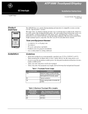
... indicate the current status of compatible security systems (see the "Specifications" section). Tools and Equipment Needed • 4-conductor, 22- The door can be reattached later if desired. The door can be activated anytime. Touchpad Wire Length Between Touchpad and Panel 750 feet 300 feet...included) • Panhead screws for gang box installation • Saw or utility knife for cutting wallboard Guidelines • Mount the touchpad in speaker provides alarm, status, and button-press sounds. See the panel installation instructions for the swing-down cover. • ...
... indicate the current status of compatible security systems (see the "Specifications" section). Tools and Equipment Needed • 4-conductor, 22- The door can be reattached later if desired. The door can be activated anytime. Touchpad Wire Length Between Touchpad and Panel 750 feet 300 feet...included) • Panhead screws for gang box installation • Saw or utility knife for cutting wallboard Guidelines • Mount the touchpad in speaker provides alarm, status, and button-press sounds. See the panel installation instructions for the swing-down cover. • ...
Installation Instructions
Page 2
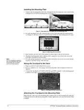
... at the marked locations where studs are not present. 4. Mounting Hole Locations 3. Insert anchors into the bottom of the touchpad. 2 ATP1000 Touchpad/Display Installation Instructions Align the mounting plate holes with the slots on the wall and mark the mounting holes (see Table ...mounting plate with the wall or gang box screw holes and secure the back plate using the screws provided. 5. Touchpad Wiring Connections Attaching the Touchpad to the matching panel terminals (see Figure 1). Separating the Touchpad from mounting properly. For wall mounting, place the mounting ...
... at the marked locations where studs are not present. 4. Mounting Hole Locations 3. Insert anchors into the bottom of the touchpad. 2 ATP1000 Touchpad/Display Installation Instructions Align the mounting plate holes with the slots on the wall and mark the mounting holes (see Table ...mounting plate with the wall or gang box screw holes and secure the back plate using the screws provided. 5. Touchpad Wiring Connections Attaching the Touchpad to the matching panel terminals (see Figure 1). Separating the Touchpad from mounting properly. For wall mounting, place the mounting ...
Installation Instructions
Page 3
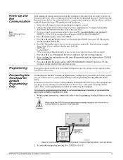
... scans the bus for the newly installed touchpad (such as a programming touchpad, be careful not to each bus device. 1. Alphanumeric touchpads briefly show the date and time display.... b o th F e a tu re s C 7 p re s s b o th S ta tu s D * S ta y 2 S ile n t 5 S y s te m 8 L ig h ts 0 A w ay 3 P ag e r 6 M enu 9 B yp ass # PROGRAMMING TOUCHPAD CABLE (60-791) 8642G29A.DSF Figure 4. Press ƒ and the display shows SECURITY. 5. Connecting a Programming Touchpad-Concord Express Shown, Concord Similar 2. ID 0-02110185* *The 8-digit SuperBus ID number is correct. 2.
... scans the bus for the newly installed touchpad (such as a programming touchpad, be careful not to each bus device. 1. Alphanumeric touchpads briefly show the date and time display.... b o th F e a tu re s C 7 p re s s b o th S ta tu s D * S ta y 2 S ile n t 5 S y s te m 8 L ig h ts 0 A w ay 3 P ag e r 6 M enu 9 B yp ass # PROGRAMMING TOUCHPAD CABLE (60-791) 8642G29A.DSF Figure 4. Press ƒ and the display shows SECURITY. 5. Connecting a Programming Touchpad-Concord Express Shown, Concord Similar 2. ID 0-02110185* *The 8-digit SuperBus ID number is correct. 2.
Installation Instructions
Page 4
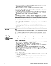
... or darkens the background. The display shows SYSTEM MENU, then TIME AND DATE (Concord panels with software versions 1.0-1.6: To prevent a trouble condition, you must delete the programming touchpad unit number from the panel header. To adjust display contrast: 1. Enter configuration mode... 9 + user, partition, or system master CODE. Removing the programming touchpad from Concord panels with software versions 1.0-1.6 display USER CODES.) 2. Exit program mode and disconnect the programming cable from Concord panel memory before activating alarms, to help compensate for at least two ...
... or darkens the background. The display shows SYSTEM MENU, then TIME AND DATE (Concord panels with software versions 1.0-1.6: To prevent a trouble condition, you must delete the programming touchpad unit number from the panel header. To adjust display contrast: 1. Enter configuration mode... 9 + user, partition, or system master CODE. Removing the programming touchpad from Concord panels with software versions 1.0-1.6 display USER CODES.) 2. Exit program mode and disconnect the programming cable from Concord panel memory before activating alarms, to help compensate for at least two ...
Installation Instructions
Page 5
...). Do not use unit number 15 in . 3. However, if the new touchpad unit number has never been ATP1000 Touchpad/Display Installation Instructions 5 Check the touchpad display contrast setting. Note At this page). (Concord panels with software versions 1.01.6 only.) Changing the Touchpad Unit Number (Concord Panels with Software Version 1.0-1.6 Only) Use the following guidelines when changing...
...). Do not use unit number 15 in . 3. However, if the new touchpad unit number has never been ATP1000 Touchpad/Display Installation Instructions 5 Check the touchpad display contrast setting. Note At this page). (Concord panels with software versions 1.01.6 only.) Changing the Touchpad Unit Number (Concord Panels with Software Version 1.0-1.6 Only) Use the following guidelines when changing...
Installation Instructions
Page 6
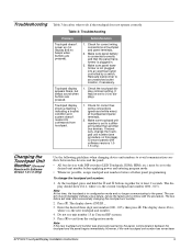
...to operate the equipment. If this is no guarantee that is the only installed touchpad, remove panel AC and battery power, then re-apply power. Concord is encouraged to try to part 15 of GE Interlogix. See the specific panel Installation Instructions for a Class B digital device,... Installation Instructions for complete UL installation requirements for help. ) ©2003 GE Interlogix. This equipment generates, uses, and can radiate radio frequency energy and, if not installed and used by one touchpad, go to scan bus devices as follows: For systems where this equipment does...
...to operate the equipment. If this is no guarantee that is the only installed touchpad, remove panel AC and battery power, then re-apply power. Concord is encouraged to try to part 15 of GE Interlogix. See the specific panel Installation Instructions for a Class B digital device,... Installation Instructions for complete UL installation requirements for help. ) ©2003 GE Interlogix. This equipment generates, uses, and can radiate radio frequency energy and, if not installed and used by one touchpad, go to scan bus devices as follows: For systems where this equipment does...


