Installation Instructions
Page 1
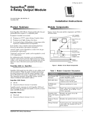
... a burglary alarm. SuperBus® 2000 4-Relay Output Module ITI Part No. 60-770 Document Number: 466-1608 Rev. SuperBus® 2000 4-Relay Output Module 1 UNIT NUMBER DIP SWITCHES BUS STATUS LED (RED) POWER LED (GREEN) OUTPUT RELAYS (4) SOFTWARE VERSION LABEL SUPERBUS 2000 DEVICE ID NUMBER LABEL WIRING TERMINALS 9710G01A.DSF Figure 1. SuperBus 2000 vs. When the panel is provided by the panel. Output Relays Form C (dry contact) output relays rated...
... a burglary alarm. SuperBus® 2000 4-Relay Output Module ITI Part No. 60-770 Document Number: 466-1608 Rev. SuperBus® 2000 4-Relay Output Module 1 UNIT NUMBER DIP SWITCHES BUS STATUS LED (RED) POWER LED (GREEN) OUTPUT RELAYS (4) SOFTWARE VERSION LABEL SUPERBUS 2000 DEVICE ID NUMBER LABEL WIRING TERMINALS 9710G01A.DSF Figure 1. SuperBus 2000 vs. When the panel is provided by the panel. Output Relays Form C (dry contact) output relays rated...
Installation Instructions
Page 4
... 70. Wiring the Module to the panel terminals or connector. *ALSO OUTPUT AND AUX. Installation Wiring Note A) Class 2, Class 3, and power-limited fire alarm circuits must be installed using FPL, FPLR, FPLP, or substitute cable permitted by a nonconductive barrier. Note For specific wiring details, see the device Installation Instructions. 4 SuperBus® 2000 4-Relay Output Module Turn off (or...
... 70. Wiring the Module to the panel terminals or connector. *ALSO OUTPUT AND AUX. Installation Wiring Note A) Class 2, Class 3, and power-limited fire alarm circuits must be installed using FPL, FPLR, FPLP, or substitute cable permitted by a nonconductive barrier. Note For specific wiring details, see the device Installation Instructions. 4 SuperBus® 2000 4-Relay Output Module Turn off (or...
Installation Instructions
Page 5
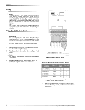
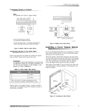
... Connecting Devices to the Zone Input Follow the maximum zone input wire length (run based on the type of wire used. Installing the Reed Switch SuperBus® 2000 4-Relay Output Module 5 Wire Run* 18 750 Feet 22 300 Feet *Wire run ) ...alarm. INPUT) ** 2K OHM 1/2 W (TYPICAL) LED Installing a Cover Tamper Switch 1 2 3 4 5 6 7 8 9 10 11 12 13 14 15 16 17 18 NORMALLY CLOSED (N/C) CONTACTS IN SERIES < OR > NORMALLY OPEN (N/O) CONTACTS IN PARALLEL * DO NOT EXCEED RELAY CONTACT VOLTAGE AND CURRENT RATINGS ** DO NOT EXCEED PANEL +12V POWER CONSUMPTION LIMITS (SEE PANEL...
... Connecting Devices to the Zone Input Follow the maximum zone input wire length (run based on the type of wire used. Installing the Reed Switch SuperBus® 2000 4-Relay Output Module 5 Wire Run* 18 750 Feet 22 300 Feet *Wire run ) ...alarm. INPUT) ** 2K OHM 1/2 W (TYPICAL) LED Installing a Cover Tamper Switch 1 2 3 4 5 6 7 8 9 10 11 12 13 14 15 16 17 18 NORMALLY CLOSED (N/C) CONTACTS IN SERIES < OR > NORMALLY OPEN (N/O) CONTACTS IN PARALLEL * DO NOT EXCEED RELAY CONTACT VOLTAGE AND CURRENT RATINGS ** DO NOT EXCEED PANEL +12V POWER CONSUMPTION LIMITS (SEE PANEL...
Installation Instructions
Page 8
...with the limits for a Class B digital device, pursuant to radio communications. SuperBus® 2000 4-Relay Output Module FCC Part 15 Class A This equipment has been tested and found to ... Temperature: -30° to 140° F (-34° to 60° C) Operating Temperature: 32° to 140° F (0° to 60° C), up to 140° F (60° C) under temporary conditions Maximum Humidity: 90% relative humidity, non... in panel cabinet mounting Listings (for ancillary use only): UL 365 Police Station Connected Burglar Alarm Units and Systems UL 609 Local Burglar Alarm Units...
...with the limits for a Class B digital device, pursuant to radio communications. SuperBus® 2000 4-Relay Output Module FCC Part 15 Class A This equipment has been tested and found to ... Temperature: -30° to 140° F (-34° to 60° C) Operating Temperature: 32° to 140° F (0° to 60° C), up to 140° F (60° C) under temporary conditions Maximum Humidity: 90% relative humidity, non... in panel cabinet mounting Listings (for ancillary use only): UL 365 Police Station Connected Burglar Alarm Units and Systems UL 609 Local Burglar Alarm Units...


