Installation Instructions
Page 1
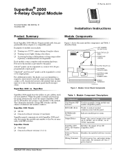
... Figure 1. Output Relays Form C (dry contact) output relays rated 4A @ 24VDC, 4A @ 24VAC, 1A @ 70VAC maximum. UltraGard® and Concord™ panels can be expanded to provide tamper protection. B November 2000 8557109A.DS4 Installation Instructions Product Summary Module Components Each SuperBus 2000 4-Relay Output module adds four programmable relay outputs to a compatible panel. SuperBus 2000 vs. This eliminates manually setting DIP switches and the chance of 32 output points. SuperBus® 2000 4-Relay Output Module ITI Part No. 60-770 Document Number: 466-1608...
... Figure 1. Output Relays Form C (dry contact) output relays rated 4A @ 24VDC, 4A @ 24VAC, 1A @ 70VAC maximum. UltraGard® and Concord™ panels can be expanded to provide tamper protection. B November 2000 8557109A.DS4 Installation Instructions Product Summary Module Components Each SuperBus 2000 4-Relay Output module adds four programmable relay outputs to a compatible panel. SuperBus 2000 vs. This eliminates manually setting DIP switches and the chance of 32 output points. SuperBus® 2000 4-Relay Output Module ITI Part No. 60-770 Document Number: 466-1608...

Installation Instructions
Page 2
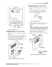
... the mounting holes (Figure 3). 3. Installation Guidelines Installation Guidelines Installation u For the maximum number of bus devices and touchpads per panel see Table 3). u When using panel power for bus devices and hardwired detectors (see specific panel Installation Instructions). Tools and Supplies Needed The relay output module can be mounted on a wall. Removing the Cover 2. Refer to the module (see Table 2. Concord 22 ga. 350 ft./18 ga. 900 ft. PRESS DOWN HERE AND PULL AWAY FROM...
... the mounting holes (Figure 3). 3. Installation Guidelines Installation Guidelines Installation u For the maximum number of bus devices and touchpads per panel see Table 3). u When using panel power for bus devices and hardwired detectors (see specific panel Installation Instructions). Tools and Supplies Needed The relay output module can be mounted on a wall. Removing the Cover 2. Refer to the module (see Table 2. Concord 22 ga. 350 ft./18 ga. 900 ft. PRESS DOWN HERE AND PULL AWAY FROM...
Installation Instructions
Page 3
... 6). plied with Concord panel accessory package) Figure 6. Mounting Holes Mounting the Module in Figure 5 (sup- Remove the module cover and set it aside (Figure 2). 3. Secure the back-plate to the cabinet using three ¼-inch #6-32 self-tapping screws (not included). Mounting Module in the top-right corner of the module onto the support standoff (see detail in Concord Cabinet SuperBus® 2000 4-Relay Output Module 3 Note The...
... 6). plied with Concord panel accessory package) Figure 6. Mounting Holes Mounting the Module in Figure 5 (sup- Remove the module cover and set it aside (Figure 2). 3. Secure the back-plate to the cabinet using three ¼-inch #6-32 self-tapping screws (not included). Mounting Module in the top-right corner of the module onto the support standoff (see detail in Concord Cabinet SuperBus® 2000 4-Relay Output Module 3 Note The...
Installation Instructions
Page 4
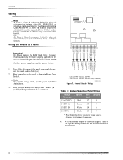
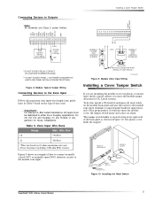
On Advent panels, the BUS 1 and BUS 2 headers must be power limited. Do not mix fire and burglary bus devices on either panel connector.) 4. TO ZONE 1 INPUT DEVICE(S) TO PANEL SUPERBUS TERMINALS OR CONNECTOR (SEE TABLE) TO OUTPUT 4 DEVICE TO OUTPUT 3 DEVICE TO OUTPUT 2 DEVICE TO OUTPUT 1 DEVICE 1. Note For specific wiring details, see the device Installation Instructions. 4 SuperBus® 2000 4-Relay Output Module OR (B) Class 2, Class 3, and power-limited fire alarm circuit conductors...
On Advent panels, the BUS 1 and BUS 2 headers must be power limited. Do not mix fire and burglary bus devices on either panel connector.) 4. TO ZONE 1 INPUT DEVICE(S) TO PANEL SUPERBUS TERMINALS OR CONNECTOR (SEE TABLE) TO OUTPUT 4 DEVICE TO OUTPUT 3 DEVICE TO OUTPUT 2 DEVICE TO OUTPUT 1 DEVICE 1. Note For specific wiring details, see the device Installation Instructions. 4 SuperBus® 2000 4-Relay Output Module OR (B) Class 2, Class 3, and power-limited fire alarm circuit conductors...
Installation Instructions
Page 5
... maximum zone input wire length (run based on the type of wire used. INPUT) ** 2K OHM 1/2 W (TYPICAL) LED Installing a Cover Tamper Switch 1 2 3 4 5 6 7 8 9 10 11 12 13 14 15 16 17 18 NORMALLY CLOSED (N/C) CONTACTS IN SERIES < OR > NORMALLY OPEN (N/O) CONTACTS IN PARALLEL * DO NOT EXCEED RELAY CONTACT VOLTAGE AND CURRENT RATINGS ** DO NOT EXCEED PANEL +12V POWER CONSUMPTION LIMITS (SEE PANEL INSTALLATION INSTRUCTIONS) Figure 8. Installing the Reed Switch SuperBus® 2000 4-Relay Output Module 5 Zone Input Wire...
... maximum zone input wire length (run based on the type of wire used. INPUT) ** 2K OHM 1/2 W (TYPICAL) LED Installing a Cover Tamper Switch 1 2 3 4 5 6 7 8 9 10 11 12 13 14 15 16 17 18 NORMALLY CLOSED (N/C) CONTACTS IN SERIES < OR > NORMALLY OPEN (N/O) CONTACTS IN PARALLEL * DO NOT EXCEED RELAY CONTACT VOLTAGE AND CURRENT RATINGS ** DO NOT EXCEED PANEL +12V POWER CONSUMPTION LIMITS (SEE PANEL INSTALLATION INSTRUCTIONS) Figure 8. Installing the Reed Switch SuperBus® 2000 4-Relay Output Module 5 Zone Input Wire...
Installation Instructions
Page 6
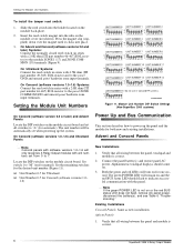
... use in series with the panel. Locate the DIP switches on . 3. Set switch 1 to "A" (for one second. u Unit Number 0-7 for UltraGard u Unit Number 0-7 for manual). Existing Installations Concord Panels- Alphanumeric touchpad displays should flash to indicate successful communication with a 2.0K ohm (ITI part number 46-467) EOL resistor to power up the system. On Concord (software versions 1.0-1.6) Systems: Connect the reed switch in Concord RF systems. M ON A 1 234567 8 9712G09A.DSF Figure 11. Module Unit Number DIP Switch Settings (Non-SuperBus 2000 systems) On Concord...
... use in series with the panel. Locate the DIP switches on . 3. Set switch 1 to "A" (for one second. u Unit Number 0-7 for UltraGard u Unit Number 0-7 for manual). Existing Installations Concord Panels- Alphanumeric touchpad displays should flash to indicate successful communication with a 2.0K ohm (ITI part number 46-467) EOL resistor to power up the system. On Concord (software versions 1.0-1.6) Systems: Connect the reed switch in Concord RF systems. M ON A 1 234567 8 9712G09A.DSF Figure 11. Module Unit Number DIP Switch Settings (Non-SuperBus 2000 systems) On Concord...

Installation Instructions
Page 7
... module outputs, adding (learning) hardwire sensors, and testing. Set the UltraGard panel RUN/PROGRAM switch to module problems. Table 6: Troubleshooting Problem Solution The green POWER 1. Make sure panel AC power is repeatedly "resetting" the 3 minute timer (see specific panel Installation Instructions). 4. One output stays activated. 1. If the alphanumeric touchpad displays 1-OFF and the 1 is set to get the panel into program mode. Troubleshooting Use the following table to determine possible solutions to PROGRAM. LED stays off , replace the module...
... module outputs, adding (learning) hardwire sensors, and testing. Set the UltraGard panel RUN/PROGRAM switch to module problems. Table 6: Troubleshooting Problem Solution The green POWER 1. Make sure panel AC power is repeatedly "resetting" the 3 minute timer (see specific panel Installation Instructions). 4. One output stays activated. 1. If the alphanumeric touchpad displays 1-OFF and the 1 is set to get the panel into program mode. Troubleshooting Use the following table to determine possible solutions to PROGRAM. LED stays off , replace the module...
Installation Instructions
Page 8
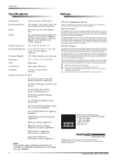
...-rated, hardwire zone Outputs: Four, panel programmable outputs with the limits for a class A digital device, pursuant to the User Changes or modifications not expressly approved by turning the equipment off and on different branch circuits. FCC Part 15 Class A This equipment has been tested and found to comply with the instructions, may cause harmful interference to operate the equipment. This equipment generates, uses, and...
...-rated, hardwire zone Outputs: Four, panel programmable outputs with the limits for a class A digital device, pursuant to the User Changes or modifications not expressly approved by turning the equipment off and on different branch circuits. FCC Part 15 Class A This equipment has been tested and found to comply with the instructions, may cause harmful interference to operate the equipment. This equipment generates, uses, and...


