8512680 - Component Replacement Manual
Page 5
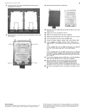
... replaced was not the C drive, complete any key on your keyboard and follow the on the bottom of the notebook for important safety, regulatory, and legal information. © 2007 Gateway, Inc. Technical Support See the label on -screen instructions. All other countries. Screw Screw Screw Screw 14 Place ...Replace the screws removed in Step 12. 16 Slide the new hard drive kit into your notebook. 17 Replace the hard drive bay cover, then tighten the cover screws. 18 Insert the battery, then turn your notebook over. 19 Connect the power adapter, modem cable, and network cable 20 If your...
... replaced was not the C drive, complete any key on your keyboard and follow the on the bottom of the notebook for important safety, regulatory, and legal information. © 2007 Gateway, Inc. Technical Support See the label on -screen instructions. All other countries. Screw Screw Screw Screw 14 Place ...Replace the screws removed in Step 12. 16 Slide the new hard drive kit into your notebook. 17 Replace the hard drive bay cover, then tighten the cover screws. 18 Insert the battery, then turn your notebook over. 19 Connect the power adapter, modem cable, and network cable 20 If your...
8512680 - Component Replacement Manual
Page 7
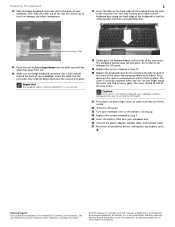
...eMachines are firmly seated. 22 Close the LCD panel. 23 Turn your notebook over . 26 Connect the power adapter, modem cable, and network cable 27 Reconnect all peripheral devices and replace any other components. 2 17 Insert the tabs on the cover in several places until it clicks in...cover, then pressing down on both hinge covers to make sure they are trademarks or registered trademarks of the notebook for important safety, regulatory, and legal information. © 2007 Gateway, Inc. Technical Support See the label on the back. All other countries. Clip 15 Place the new keyboard...
...eMachines are firmly seated. 22 Close the LCD panel. 23 Turn your notebook over . 26 Connect the power adapter, modem cable, and network cable 27 Reconnect all peripheral devices and replace any other components. 2 17 Insert the tabs on the cover in several places until it clicks in...cover, then pressing down on both hinge covers to make sure they are trademarks or registered trademarks of the notebook for important safety, regulatory, and legal information. © 2007 Gateway, Inc. Technical Support See the label on the back. All other countries. Clip 15 Place the new keyboard...
8512680 - Component Replacement Manual
Page 11
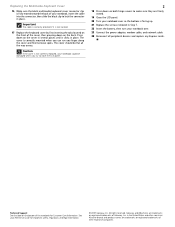
... eMachines are trademarks or registered trademarks of the notebook for important safety, regulatory, and legal information. © 2007 Gateway, Inc. in place. Press down on the cover in several places until it is not twisted. 17 Replace the keyboard cover by first inserting the tabs located on the front of ... when you can run you try to close the LCD panel. 2 18 Press down on the bottom of Gateway, Inc. Caution If the cover is not correctly replaced, your notebook could be flat all peripheral devices and replace any Express cards. Replacing the Multimedia Keyboard Cover 16 Make sure...
... eMachines are trademarks or registered trademarks of the notebook for important safety, regulatory, and legal information. © 2007 Gateway, Inc. in place. Press down on the cover in several places until it is not twisted. 17 Replace the keyboard cover by first inserting the tabs located on the front of ... when you can run you try to close the LCD panel. 2 18 Press down on the bottom of Gateway, Inc. Caution If the cover is not correctly replaced, your notebook could be flat all peripheral devices and replace any Express cards. Replacing the Multimedia Keyboard Cover 16 Make sure...

8512680 - Component Replacement Manual
Page 13
...removed in the module slot. 14 Move the antenna wires out of the notebook for important safety, regulatory, and legal information. © 2007 Gateway, Inc. Gateway and eMachines are trademarks or registered trademarks of Gateway, Inc. All other countries. Note which color cable is keyed so ...one direction. This module is connected to the connectors. 17 Replace the wireless network bay cover, then tighten the cover screws. 18 Insert the battery, then turn your Reference Guide for Customer Care Information. See your notebook over. 19 Connect the power adapter, modem cable,...
...removed in the module slot. 14 Move the antenna wires out of the notebook for important safety, regulatory, and legal information. © 2007 Gateway, Inc. Gateway and eMachines are trademarks or registered trademarks of Gateway, Inc. All other countries. Note which color cable is keyed so ...one direction. This module is connected to the connectors. 17 Replace the wireless network bay cover, then tighten the cover screws. 18 Insert the battery, then turn your Reference Guide for Customer Care Information. See your notebook over. 19 Connect the power adapter, modem cable,...

8512568 - Gateway Notebook Reference Guide R0
Page 25
... is firmly attached to toggle the status lights on page 3. 17 For more information, see "Front" on the Customer Care label. The battery charge indicator turns on (see "Gateway contact information" on and off your notebook and leave your notebook's power connector. 3 Plug the power cord into a wall outlet...on, complete the following steps until the battery charge indicator turns blue. www.gateway.com 2 Connect the AC adapter to your notebook connected to AC power until it turns on: • Unplug the adapter from your notebook, then plug it back in. • Press FN+F1 to the AC ...
... is firmly attached to toggle the status lights on page 3. 17 For more information, see "Front" on the Customer Care label. The battery charge indicator turns on (see "Gateway contact information" on and off your notebook and leave your notebook's power connector. 3 Plug the power cord into a wall outlet...on, complete the following steps until the battery charge indicator turns blue. www.gateway.com 2 Connect the AC adapter to your notebook connected to AC power until it turns on: • Unplug the adapter from your notebook, then plug it back in. • Press FN+F1 to the AC ...
8512568 - Gateway Notebook Reference Guide R0
Page 118
... all peripheral devices and replace any key on -screen instructions. CHAPTER 8: Upgrading Your Notebook 15 Replace the screws that secure the bracket to the drive. 16 Slide the new hard drive kit into your notebook. 17 Replace the cover, then tighten the screws. 18 Insert the battery, then turn your... notebook over. 19 Connect the power adapter, modem cable, and network cable. 20 If your notebook uses RAID, read the section "Setting up an optional ...
... all peripheral devices and replace any key on -screen instructions. CHAPTER 8: Upgrading Your Notebook 15 Replace the screws that secure the bracket to the drive. 16 Slide the new hard drive kit into your notebook. 17 Replace the cover, then tighten the screws. 18 Insert the battery, then turn your... notebook over. 19 Connect the power adapter, modem cable, and network cable. 20 If your notebook uses RAID, read the section "Setting up an optional ...


