8512055 - Component Replacement Manual
Page 7
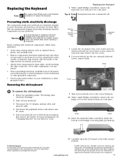
...the two hinge cover screws and put it to the fully opened position. Memory bay Wireless network bay Keyboard screw 7 Loosen the six memory bay cover screws and one wireless network bay screw (these guidelines: • Avoid static-causing surfaces such as electrostatic ...5 Turn your workbench or other brands and product names are trademarks or registered trademarks of their respective companies. 1 www.gateway.com © 2007 Gateway, Inc. Avoid touching the edge connectors. Screw Screw 11 Insert the small flat-blade screwdriver under "Preventing static electricity ...
...the two hinge cover screws and put it to the fully opened position. Memory bay Wireless network bay Keyboard screw 7 Loosen the six memory bay cover screws and one wireless network bay screw (these guidelines: • Avoid static-causing surfaces such as electrostatic ...5 Turn your workbench or other brands and product names are trademarks or registered trademarks of their respective companies. 1 www.gateway.com © 2007 Gateway, Inc. Avoid touching the edge connectors. Screw Screw 11 Insert the small flat-blade screwdriver under "Preventing static electricity ...
8512055 - Component Replacement Manual
Page 8
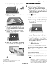
... under the right hinge cover and gently pry it up . 9 Replace the two optional keyboard screws. 10 Replace the memory bay cover and wireless network bay cover. 11 Replace the keyboard screw. 12 Insert the battery, then turn your notebook over . 13 Connect the power adapter, the... the cable into place. Press down on the front edge of the notebook for important safety, regulatory, and legal information. 2 www.gateway.com © 2007 Gateway, Inc. All rights reserved. in place. See your notebook could be flat all the way across . Replacing the Keyboard Installing the new...
... under the right hinge cover and gently pry it up . 9 Replace the two optional keyboard screws. 10 Replace the memory bay cover and wireless network bay cover. 11 Replace the keyboard screw. 12 Insert the battery, then turn your notebook over . 13 Connect the power adapter, the... the cable into place. Press down on the front edge of the notebook for important safety, regulatory, and legal information. 2 www.gateway.com © 2007 Gateway, Inc. All rights reserved. in place. See your notebook could be flat all the way across . Replacing the Keyboard Installing the new...
8512055 - Component Replacement Manual
Page 11
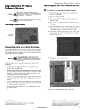
... module: 1 Follow the guidelines under "Preventing static electricity discharge." 2 Turn off your notebook, may be removed), then remove wireless network bay cover. Gateway and eMachines are ready to a bare metal part of your workbench or other grounded object. 7 Unplug the two antenna cables. 8 Move the antenna cables out ...
... module: 1 Follow the guidelines under "Preventing static electricity discharge." 2 Turn off your notebook, may be removed), then remove wireless network bay cover. Gateway and eMachines are ready to a bare metal part of your workbench or other grounded object. 7 Unplug the two antenna cables. 8 Move the antenna cables out ...
8512055 - Component Replacement Manual
Page 12
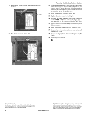
... the Wireless Network Module 11 Hold the new module at a 30-degree angle and insert it can only be inserted in the United States and other brands and product names are trademarks or registered trademarks of the slot. Technical Support See the label on your notebook. Gateway and eMachines... cable to the connector labelled MAIN or M, then reattach the light gray antenna cable to the connector labelled AUX or A. 15 Replace the wireless network bay cover, then tighten the cover screw. 16 Insert the battery, then turn your Reference Guide for Customer Care Information. Screw 10 ...
... the Wireless Network Module 11 Hold the new module at a 30-degree angle and insert it can only be inserted in the United States and other brands and product names are trademarks or registered trademarks of the slot. Technical Support See the label on your notebook. Gateway and eMachines... cable to the connector labelled MAIN or M, then reattach the light gray antenna cable to the connector labelled AUX or A. 15 Replace the wireless network bay cover, then tighten the cover screw. 16 Insert the battery, then turn your Reference Guide for Customer Care Information. Screw 10 ...


