8512055 - Component Replacement Manual
Page 1
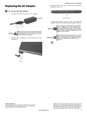
... Care at the Web address or telephone number shown on the label on the bottom of Gateway, Inc. in . Replacing the AC Adapter 3 Plug the power cord into a wall outlet. The power indicator turns on , unplug the adapter from your Reference Guide for Customer Care Information. The AC adapter has no user-replaceable or user-serviceable parts inside. Technical Support See the label on the bottom of...
... Care at the Web address or telephone number shown on the label on the bottom of Gateway, Inc. in . Replacing the AC Adapter 3 Plug the power cord into a wall outlet. The power indicator turns on , unplug the adapter from your Reference Guide for Customer Care Information. The AC adapter has no user-replaceable or user-serviceable parts inside. Technical Support See the label on the bottom of...
8512055 - Component Replacement Manual
Page 2
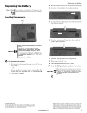
... of explosion if the battery is not connected to AC power, save your work and turn blue after three hours, contact Gateway Customer Care at the Web address or telephone number shown on the label on the bottom of the battery as hazardous waste. See your Reference Guide for your notebook into an AC outlet. 10 Open the LCD panel and press the power button.
... of explosion if the battery is not connected to AC power, save your work and turn blue after three hours, contact Gateway Customer Care at the Web address or telephone number shown on the label on the bottom of the battery as hazardous waste. See your Reference Guide for your notebook into an AC outlet. 10 Open the LCD panel and press the power button.
8512055 - Component Replacement Manual
Page 3
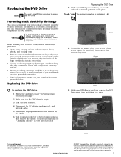
..., see "Changing Batteries" in your notebook over any PC Cards. 6 Turn your Reference Guide. in the United States and other grounded object. Before working with a K. Avoid touching the edge connectors. Replacing the DVD drive To replace the DVD drive: 1 Follow the guidelines under "Preventing static electricity discharge." 2 Make sure that the DVD drive is marked with notebook components, follow these screws cannot be removed), then remove the memory bay cover. Screws Screws...
..., see "Changing Batteries" in your notebook over any PC Cards. 6 Turn your Reference Guide. in the United States and other grounded object. Before working with a K. Avoid touching the edge connectors. Replacing the DVD drive To replace the DVD drive: 1 Follow the guidelines under "Preventing static electricity discharge." 2 Make sure that the DVD drive is marked with notebook components, follow these screws cannot be removed), then remove the memory bay cover. Screws Screws...
8512055 - Component Replacement Manual
Page 4
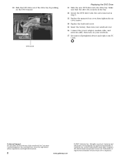
... notebook over. 16 Connect the power adapter, modem cable, and network cable, then turn on the DVD bracket. All other countries. DVD bracket Replacing the DVD Drive 11 Slide the new DVD drive into the drive bay. 10 Slide the DVD drive out of the drive bay by pushing on your notebook. 17 Reconnect all peripheral devices and replace any PC Cards. in Step 9. 13 Replace the memory bay cover, then tighten the six cover screws. 14 Replace the keyboard...
... notebook over. 16 Connect the power adapter, modem cable, and network cable, then turn on the DVD bracket. All other countries. DVD bracket Replacing the DVD Drive 11 Slide the new DVD drive into the drive bay. 10 Slide the DVD drive out of the drive bay by pushing on your notebook. 17 Reconnect all peripheral devices and replace any PC Cards. in Step 9. 13 Replace the memory bay cover, then tighten the six cover screws. 14 Replace the keyboard...
8512055 - Component Replacement Manual
Page 5
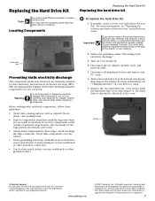
... connection. • Touch a bare metal surface on the bottom of your notebook. 2 Follow the guidelines under "Preventing static electricity discharge." 3 Turn off your notebook. 4 Disconnect the AC adapter, modem cable, and network cable. 5 Disconnect all peripheral devices and remove any PC Cards. 6 Turn your Reference Guide. 7 Remove the two hard drive bay cover screws, slide the hard drive bay cover, then remove it to the back of the notebook for software and device driver recovery" in your notebook...
... connection. • Touch a bare metal surface on the bottom of your notebook. 2 Follow the guidelines under "Preventing static electricity discharge." 3 Turn off your notebook. 4 Disconnect the AC adapter, modem cable, and network cable. 5 Disconnect all peripheral devices and remove any PC Cards. 6 Turn your Reference Guide. 7 Remove the two hard drive bay cover screws, slide the hard drive bay cover, then remove it to the back of the notebook for software and device driver recovery" in your notebook...
8512055 - Component Replacement Manual
Page 6
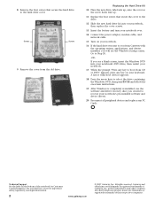
...-screen instructions. 19 After Windows is completely re-installed, use the software and driver recovery discs you created to Step 20. -OR- Screws Screws 9 Remove the cover from the old drive. If you will see a blank screen, insert the Windows DVD into your notebook's DVD drive, then restart your notebook. 17 When the prompt "Press any key to the hard drive cover. A list of Gateway, Inc. Go to recover your notebook's pre-installed software and device drivers. 20 Reconnect all peripheral devices and replace...
...-screen instructions. 19 After Windows is completely re-installed, use the software and driver recovery discs you created to Step 20. -OR- Screws Screws 9 Remove the cover from the old drive. If you will see a blank screen, insert the Windows DVD into your notebook's DVD drive, then restart your notebook. 17 When the prompt "Press any key to the hard drive cover. A list of Gateway, Inc. Go to recover your notebook's pre-installed software and device drivers. 20 Reconnect all peripheral devices and replace...
8512055 - Component Replacement Manual
Page 7
... six memory bay cover screws and one wireless network bay screw (these guidelines: • Avoid static-causing surfaces such as electrostatic discharge (ESD). All other grounded object. Replacing the Keyboard Tools You need a small Phillips and a small flat-blade screwdriver to dangerous electrical voltages and moving parts, turn off your notebook. 3 Disconnect the AC adapter, modem cable, and network cable. 4 Disconnect all peripheral devices and remove...
... six memory bay cover screws and one wireless network bay screw (these guidelines: • Avoid static-causing surfaces such as electrostatic discharge (ESD). All other grounded object. Replacing the Keyboard Tools You need a small Phillips and a small flat-blade screwdriver to dangerous electrical voltages and moving parts, turn off your notebook. 3 Disconnect the AC adapter, modem cable, and network cable. 4 Disconnect all peripheral devices and remove...
8512055 - Component Replacement Manual
Page 8
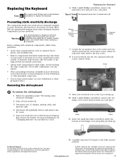
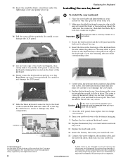
... flat all the way across . Be careful not to close the LCD panel. 7 Close the LCD panel, then replace the two hinge cover screws. 8 Turn your notebook over . 13 Connect the power adapter, the modem cable, and the network cable, then turn on your notebook. Replacing the Keyboard Installing the new keyboard To install the new keyboard: 1 Place the new keyboard keys-down on the cover in several places until it is almost face-up . 14 Pull the...
... flat all the way across . Be careful not to close the LCD panel. 7 Close the LCD panel, then replace the two hinge cover screws. 8 Turn your notebook over . 13 Connect the power adapter, the modem cable, and the network cable, then turn on your notebook. Replacing the Keyboard Installing the new keyboard To install the new keyboard: 1 Place the new keyboard keys-down on the cover in several places until it is almost face-up . 14 Pull the...
8512055 - Component Replacement Manual
Page 9
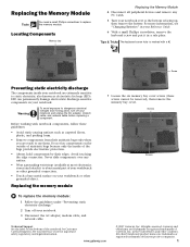
... (ESD). Screws Screws To replace the memory module: 1 Follow the guidelines under "Preventing static electricity discharge." 2 Turn off your Reference Guide. 6 With a small Phillips screwdriver, remove the keyboard screw and put it to use them. All rights reserved. For more information, see "Changing Batteries" in your notebook and unplug the AC adapter, modem cable, and network cable before replacing a component. Technical Support See the label on your...
... (ESD). Screws Screws To replace the memory module: 1 Follow the guidelines under "Preventing static electricity discharge." 2 Turn off your Reference Guide. 6 With a small Phillips screwdriver, remove the keyboard screw and put it to use them. All rights reserved. For more information, see "Changing Batteries" in your notebook and unplug the AC adapter, modem cable, and network cable before replacing a component. Technical Support See the label on your...
8512055 - Component Replacement Manual
Page 10
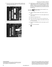
... Replace the memory bay cover, then tighten the six cover screws. 13 Replace the keyboard screw. 14 Insert the battery, then turn your notebook over. 15 Connect the power adapter, the modem cable, and the network cable. 16 Reconnect all peripheral devices and replace any PC Cards. 17 Turn on the bottom of the notebook for Customer Care Information. 8 If you are trademarks or registered trademarks of Gateway, Inc. Important Use only memory modules...
... Replace the memory bay cover, then tighten the six cover screws. 13 Replace the keyboard screw. 14 Insert the battery, then turn your notebook over. 15 Connect the power adapter, the modem cable, and the network cable. 16 Reconnect all peripheral devices and replace any PC Cards. 17 Turn on the bottom of the notebook for Customer Care Information. 8 If you are trademarks or registered trademarks of Gateway, Inc. Important Use only memory modules...
8512055 - Component Replacement Manual
Page 11
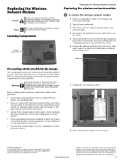
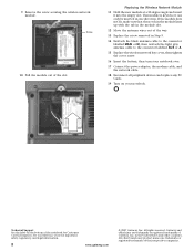
... remove wireless network bay cover. Warning To avoid exposure to a bare metal part of their edges. in your notebook are trademarks or registered trademarks of antistatic bags because only the inside your notebook. Locating Components Wireless network bay Replacing the Wireless Network Module Replacing the wireless network module To replace the wireless network module: 1 Follow the guidelines under "Preventing static electricity discharge." 2 Turn off your notebook. 3 Disconnect the AC adapter, modem cable, and network cable. 4 Disconnect all peripheral devices...
... remove wireless network bay cover. Warning To avoid exposure to a bare metal part of their edges. in your notebook are trademarks or registered trademarks of antistatic bags because only the inside your notebook. Locating Components Wireless network bay Replacing the Wireless Network Module Replacing the wireless network module To replace the wireless network module: 1 Follow the guidelines under "Preventing static electricity discharge." 2 Turn off your notebook. 3 Disconnect the AC adapter, modem cable, and network cable. 4 Disconnect all peripheral devices...
8512055 - Component Replacement Manual
Page 12
... Support See the label on your Reference Guide for Customer Care Information. See your notebook. in Step 9. 14 Reattach the black antenna cable to the connector labelled MAIN or M, then reattach the light gray antenna cable to the connector labelled AUX or A. 15 Replace the wireless network bay cover, then tighten the cover screw. 16 Insert the battery, then turn your notebook over. 17 Connect the power adapter...
... Support See the label on your Reference Guide for Customer Care Information. See your notebook. in Step 9. 14 Reattach the black antenna cable to the connector labelled MAIN or M, then reattach the light gray antenna cable to the connector labelled AUX or A. 15 Replace the wireless network bay cover, then tighten the cover screw. 16 Insert the battery, then turn your notebook over. 17 Connect the power adapter...


