8511725 - Gateway Service Guide
Page 3
... Replacing the LCD panel assembly lid 51 Replacing the palm rest 56 Replacing the modem card 59 Replacing the Bluetooth module 62 Replacing the system board 64 Replacing the external video board 67 Replacing the speakers 69 i
... Replacing the LCD panel assembly lid 51 Replacing the palm rest 56 Replacing the modem card 59 Replacing the Bluetooth module 62 Replacing the system board 64 Replacing the external video board 67 Replacing the speakers 69 i
8511725 - Gateway Service Guide
Page 5
...; Replacing the LCD panel assembly lid • Replacing the palm rest • Replacing the modem card • Replacing the Bluetooth module • Replacing the system board • Replacing the external video board • Replacing the speakers 1
...; Replacing the LCD panel assembly lid • Replacing the palm rest • Replacing the modem card • Replacing the Bluetooth module • Replacing the system board • Replacing the external video board • Replacing the speakers 1
8511725 - Gateway Service Guide
Page 20
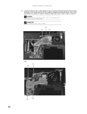
Screw Screw Screw -OR- Replacing Notebook Components 5 Loosen the three or four screws (these screws cannot be removed) that secure the cooling assembly to each screw and loosen the screws in reverse numerical order (start with 4, then 3, then 2, then 1). Important The number of screws varies by model. Use the numbers stamped in reverse numerical order. Screw Screw Screw Screw 16 Caution When loosening the cooling assembly's screws in the numbered holes, loosen them in the metal next to the system board.
Screw Screw Screw -OR- Replacing Notebook Components 5 Loosen the three or four screws (these screws cannot be removed) that secure the cooling assembly to each screw and loosen the screws in reverse numerical order (start with 4, then 3, then 2, then 1). Important The number of screws varies by model. Use the numbers stamped in reverse numerical order. Screw Screw Screw Screw 16 Caution When loosening the cooling assembly's screws in the numbered holes, loosen them in the metal next to the system board.
8511725 - Gateway Service Guide
Page 21
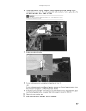
www.gateway.com 6 .At the same time as you with thermal grease already applied, place new thermal grease on the processor. Be careful not to break the ... die. 10 Plug in the new cooling fan. 11 Insert the new cooling assembly into the notebook. 17 Be careful not to the system board at this point. Caution The cooling assembly cable is attached to the system board at this point. The cooling assembly cable is attached to break the cable.
www.gateway.com 6 .At the same time as you with thermal grease already applied, place new thermal grease on the processor. Be careful not to break the ... die. 10 Plug in the new cooling fan. 11 Insert the new cooling assembly into the notebook. 17 Be careful not to the system board at this point. Caution The cooling assembly cable is attached to the system board at this point. The cooling assembly cable is attached to break the cable.
8511725 - Gateway Service Guide
Page 25
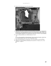
www.gateway.com 4 Remove the old processor from the system board. 5 Install the new processor onto the system board making sure that Pin 1 on the processor (indicated by the silk-screened arrow on the corner of the processor) aligns with Pin 1 on the processor ...
www.gateway.com 4 Remove the old processor from the system board. 5 Install the new processor onto the system board making sure that Pin 1 on the processor (indicated by the silk-screened arrow on the corner of the processor) aligns with Pin 1 on the processor ...
8511725 - Gateway Service Guide
Page 40
Tip You do not have access to the battery connector on the system board, go to Step 5. 36 If you do not need to complete this task: Scribe or non-marring tool 2 black (keyboard cover) 1-3 black (keyboard) To replace ..." on page 31. Phillips #0 screwdriver Screws removed during this task: Flat-blade driver - OR - If you have access to the battery connector on the system board, complete the following: a Remove the LCD panel by following the instructions in "Replacing the LCD panel assembly" on page 38. Replacing Notebook Components Replacing the...
Tip You do not have access to the battery connector on the system board, go to Step 5. 36 If you do not need to complete this task: Scribe or non-marring tool 2 black (keyboard cover) 1-3 black (keyboard) To replace ..." on page 31. Phillips #0 screwdriver Screws removed during this task: Flat-blade driver - OR - If you have access to the battery connector on the system board, complete the following: a Remove the LCD panel by following the instructions in "Replacing the LCD panel assembly" on page 38. Replacing Notebook Components Replacing the...
8511725 - Gateway Service Guide
Page 41
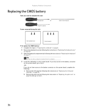
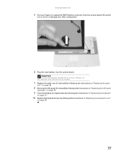
... 5 Use your fingers to touch or damage any other components. 6 Plug the new battery into the system board. Important Use only CMOS batteries designed for this Gateway notebook. The non-conductive sleeve and wires are not reusable. 7 Replace the palm rest (if removed) by following the instructions in "Replacing the palm rest...
... 5 Use your fingers to touch or damage any other components. 6 Plug the new battery into the system board. Important Use only CMOS batteries designed for this Gateway notebook. The non-conductive sleeve and wires are not reusable. 7 Replace the palm rest (if removed) by following the instructions in "Replacing the palm rest...

8511725 - Gateway Service Guide
Page 43
www.gateway.com 5 Carefully unplug the LCD video cable from under the system board, then slide the wires out from the notebook. Retaining clips Connector 6 Lift up on the video cable retaining clips slightly, then slide the video cable out from under the clips. 7 Taking care to note the cables' routing and positions as they are installed from Gateway, pull the antenna wires out from under the retaining clips. 39 Make sure you grasp the connector, not the cable.
www.gateway.com 5 Carefully unplug the LCD video cable from under the system board, then slide the wires out from the notebook. Retaining clips Connector 6 Lift up on the video cable retaining clips slightly, then slide the video cable out from under the clips. 7 Taking care to note the cables' routing and positions as they are installed from Gateway, pull the antenna wires out from under the retaining clips. 39 Make sure you grasp the connector, not the cable.
8511725 - Gateway Service Guide
Page 45
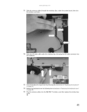
www.gateway.com 11 Slide the antenna cables through the retaining clips, under the system board, then into the wireless card area. 12 Slide the LCD video cable under the retaining clips, then plug the LCD video connector into the notebook. 13 Close the keyboard compartment by following the instructions in "Replacing the keyboard" on page 31. 14 Replace the keyboard cover by following the instructions in "Replacing the keyboard cover" on page 29. 15 Plug the antenna cables into the IEEE 802.11 wireless card, then replace the wireless bay cover. 41
www.gateway.com 11 Slide the antenna cables through the retaining clips, under the system board, then into the wireless card area. 12 Slide the LCD video cable under the retaining clips, then plug the LCD video connector into the notebook. 13 Close the keyboard compartment by following the instructions in "Replacing the keyboard" on page 31. 14 Replace the keyboard cover by following the instructions in "Replacing the keyboard cover" on page 29. 15 Plug the antenna cables into the IEEE 802.11 wireless card, then replace the wireless bay cover. 41
8511725 - Gateway Service Guide
Page 63
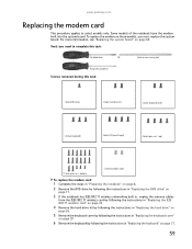
...) 17 black (palm rest - Some models of the notebook have the modem built into the system board. www.gateway.com Replacing the modem card This procedure applies to complete this task: 1 black (DVD drive) 2 black (hard drive kit) 2 black (keyboard cover) 1-3 black (keyboard) 4 black (...
...) 17 black (palm rest - Some models of the notebook have the modem built into the system board. www.gateway.com Replacing the modem card This procedure applies to complete this task: 1 black (DVD drive) 2 black (hard drive kit) 2 black (keyboard cover) 1-3 black (keyboard) 4 black (...
8511725 - Gateway Service Guide
Page 64
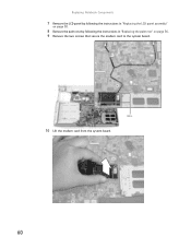
Screws 10 Lift the modem card from the system board. 60 Replacing Notebook Components 7 Remove the LCD panel by following the instructions in "Replacing the LCD panel assembly" on page 38. 8 Remove the palm rest by following the instructions in "Replacing the palm rest" on page 56. 9 Remove the two screws that secure the modem card to the system board.
Screws 10 Lift the modem card from the system board. 60 Replacing Notebook Components 7 Remove the LCD panel by following the instructions in "Replacing the LCD panel assembly" on page 38. 8 Remove the palm rest by following the instructions in "Replacing the palm rest" on page 56. 9 Remove the two screws that secure the modem card to the system board.
8511725 - Gateway Service Guide
Page 65
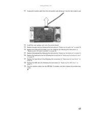
www.gateway.com 11 Unplug the modem cable from the old modem card and plug it into the new modem card. 12 Install the new modem card onto the system board. 13 Replace the palm rest by following the instructions in "Replacing the palm rest" on page 56. 14 Replace the LCD panel...
www.gateway.com 11 Unplug the modem cable from the old modem card and plug it into the new modem card. 12 Install the new modem card onto the system board. 13 Replace the palm rest by following the instructions in "Replacing the palm rest" on page 56. 14 Replace the LCD panel...
8511725 - Gateway Service Guide
Page 67
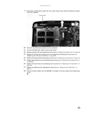
www.gateway.com 9 Disconnect the Bluetooth cable from the system board, then slide the Bluetooth module from the notebook. Bluetooth module 10 Slide the new Bluetooth module into the notebook. 11 Connect the Bluetooth cable to the system board. 12 Replace the palm rest by following the instructions in "Replacing the palm rest" on...
www.gateway.com 9 Disconnect the Bluetooth cable from the system board, then slide the Bluetooth module from the notebook. Bluetooth module 10 Slide the new Bluetooth module into the notebook. 11 Connect the Bluetooth cable to the system board. 12 Replace the palm rest by following the instructions in "Replacing the palm rest" on...

8511725 - Gateway Service Guide
Page 68
top) 17 black (palm rest - Replacing Notebook Components Replacing the system board Tools you may need to complete this task: • X-23-7762 thermal grease Screws removed during this task: Flat-blade driver - OR - Scribe or non-... (wireless card) Select models only 2 black (keyboard cover) 1-3 black (keyboard) 4 black (LCD panel hinges) 4 black (palm rest - bottom) 2 chrome (modem) Select models only 4 black (system board) To replace the system board: 1 Complete the steps in "Preparing the notebook" on page 6. 2 Remove the memory from the old system...
top) 17 black (palm rest - Replacing Notebook Components Replacing the system board Tools you may need to complete this task: • X-23-7762 thermal grease Screws removed during this task: Flat-blade driver - OR - Scribe or non-... (wireless card) Select models only 2 black (keyboard cover) 1-3 black (keyboard) 4 black (LCD panel hinges) 4 black (palm rest - bottom) 2 chrome (modem) Select models only 4 black (system board) To replace the system board: 1 Complete the steps in "Preparing the notebook" on page 6. 2 Remove the memory from the old system...

8511725 - Gateway Service Guide
Page 69
www.gateway.com 3 Remove the DVD drive by following the instructions in "Replacing the DVD drive" on page 11. 4 Remove the cooling assembly by following the instructions in "Replacing the cooling assembly" on page 14. 5 If your new system board does not include a processor, remove the processor from the old system board and install..." on page 38. 11 Remove the palm rest by following the instructions in "Replacing the palm rest" on page 56. 12 If your new system board does not have a built-in modem and did not ship to you with a new modem card (see page 60 for a picture of a modem card), remove...
www.gateway.com 3 Remove the DVD drive by following the instructions in "Replacing the DVD drive" on page 11. 4 Remove the cooling assembly by following the instructions in "Replacing the cooling assembly" on page 14. 5 If your new system board does not include a processor, remove the processor from the old system board and install..." on page 38. 11 Remove the palm rest by following the instructions in "Replacing the palm rest" on page 56. 12 If your new system board does not have a built-in modem and did not ship to you with a new modem card (see page 60 for a picture of a modem card), remove...
8511725 - Gateway Service Guide
Page 70
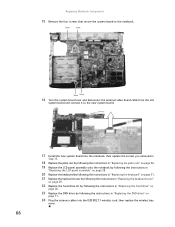
... connect it to the notebook. Replacing Notebook Components 15 Remove the four screws that secure the system board to the new system board. 17 Install the new system board into the notebook, then replace the screws you removed in Step 15. 18 Replace the palm rest by following the instructions in "Replacing the...
... connect it to the notebook. Replacing Notebook Components 15 Remove the four screws that secure the system board to the new system board. 17 Install the new system board into the notebook, then replace the screws you removed in Step 15. 18 Replace the palm rest by following the instructions in "Replacing the...
8511725 - Gateway Service Guide
Page 71
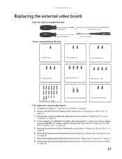
...marring tool Phillips #0 screwdriver Screws removed during this task: Flat-blade driver - bottom) 2 chrome hexnut (external video board) 2 black (external video board) To replace the external video board: 1 Complete the steps in "Preparing the notebook" on page 6. 2 Remove the DVD drive by following the instructions... 31. 8 Remove the LCD panel by following the instructions in "Replacing the LCD panel assembly" on page 38. 67 www.gateway.com Replacing the external video board Tools you need to complete this task: 5.0 mm hex nutdriver 1 black (DVD drive) 2 black (hard drive kit) 2...
...marring tool Phillips #0 screwdriver Screws removed during this task: Flat-blade driver - bottom) 2 chrome hexnut (external video board) 2 black (external video board) To replace the external video board: 1 Complete the steps in "Preparing the notebook" on page 6. 2 Remove the DVD drive by following the instructions... 31. 8 Remove the LCD panel by following the instructions in "Replacing the LCD panel assembly" on page 38. 67 www.gateway.com Replacing the external video board Tools you need to complete this task: 5.0 mm hex nutdriver 1 black (DVD drive) 2 black (hard drive kit) 2...
8511725 - Gateway Service Guide
Page 72
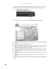
...Remove the two screws that secure the external video board to the notebook. Replacing Notebook Components 9 Remove the palm rest by following the instructions in "Replacing the DVD drive" on page 56. 10 Remove the two hex nuts that secure the external video board to the notebook. Screw Screw 12 Install the... new external video board into the notebook, then replace the screws removed in Step 11. 13 Replace the two hex nuts removed in Step...
...Remove the two screws that secure the external video board to the notebook. Replacing Notebook Components 9 Remove the palm rest by following the instructions in "Replacing the DVD drive" on page 56. 10 Remove the two hex nuts that secure the external video board to the notebook. Screw Screw 12 Install the... new external video board into the notebook, then replace the screws removed in Step 11. 13 Replace the two hex nuts removed in Step...
8511725 - Gateway Service Guide
Page 73
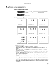
Phillips #0 screwdriver Screws removed during this task: Flat-blade driver - bottom) 4 black (system board) 2 chrome (speakers) To replace the speakers: 1 Complete the steps in "Preparing the notebook" on page 6. 2 Remove the DVD drive by following the instructions in "Replacing... 31. 8 Remove the LCD panel by following the instructions in "Replacing the LCD panel assembly" on page 38. 69 top) 17 black (palm rest - www.gateway.com Replacing the speakers Tools you need to complete this task: Scribe or non-marring tool 1 black (DVD drive) 2 black (hard drive kit) 2 black (...
Phillips #0 screwdriver Screws removed during this task: Flat-blade driver - bottom) 4 black (system board) 2 chrome (speakers) To replace the speakers: 1 Complete the steps in "Preparing the notebook" on page 6. 2 Remove the DVD drive by following the instructions in "Replacing... 31. 8 Remove the LCD panel by following the instructions in "Replacing the LCD panel assembly" on page 38. 69 top) 17 black (palm rest - www.gateway.com Replacing the speakers Tools you need to complete this task: Scribe or non-marring tool 1 black (DVD drive) 2 black (hard drive kit) 2 black (...
8511725 - Gateway Service Guide
Page 74
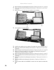
...by following the instructions in "Replacing the hard drive" on page 26. 20 Replace the DVD drive by following the instructions in "Replacing the system board" on page 11. 21 Plug the antenna cables into the IEEE 802.11 wireless card, then replace the wireless bay cover. 70 Replacing Notebook ...Components 9 Remove the palm rest by following the instructions in "Replacing the palm rest" on page 56. 10 Remove the system board by following the instructions in "Replacing the DVD drive" on page 64. 11 Remove the two screws that secure the speakers to the notebook.
...by following the instructions in "Replacing the hard drive" on page 26. 20 Replace the DVD drive by following the instructions in "Replacing the system board" on page 11. 21 Plug the antenna cables into the IEEE 802.11 wireless card, then replace the wireless bay cover. 70 Replacing Notebook ...Components 9 Remove the palm rest by following the instructions in "Replacing the palm rest" on page 56. 10 Remove the system board by following the instructions in "Replacing the DVD drive" on page 64. 11 Remove the two screws that secure the speakers to the notebook.


