8511725 - Gateway Service Guide
Page 3
... drive 26 Replacing the keyboard cover 29 Replacing the keyboard 31 Replacing the CMOS battery 36 Replacing the LCD panel assembly 38 Replacing the LCD panel inverter 42 Replacing the LCD panel 46 Replacing the LCD panel assembly lid 51 Replacing the palm rest 56 Replacing the modem card 59 Replacing the Bluetooth module...
... drive 26 Replacing the keyboard cover 29 Replacing the keyboard 31 Replacing the CMOS battery 36 Replacing the LCD panel assembly 38 Replacing the LCD panel inverter 42 Replacing the LCD panel 46 Replacing the LCD panel assembly lid 51 Replacing the palm rest 56 Replacing the modem card 59 Replacing the Bluetooth module...
8511725 - Gateway Service Guide
Page 5
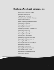
... drive • Replacing the keyboard cover • Replacing the keyboard • Replacing the CMOS battery • Replacing the LCD panel assembly • Replacing the LCD panel inverter • Replacing the LCD panel • Replacing the LCD panel assembly lid • Replacing the palm rest • Replacing the modem card • Replacing the Bluetooth module...
... drive • Replacing the keyboard cover • Replacing the keyboard • Replacing the CMOS battery • Replacing the LCD panel assembly • Replacing the LCD panel inverter • Replacing the LCD panel • Replacing the LCD panel assembly lid • Replacing the palm rest • Replacing the modem card • Replacing the Bluetooth module...
8511725 - Gateway Service Guide
Page 7
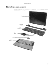
For a complete list of the notebook. LCD panel assembly (see page 38) Keyboard cover (see page 29) Keyboard (see page 31) Cooling assembly (see page 11) Processor (see page 19) Palm rest (see "Contents" on page i. www.gateway.com Identifying components Use this chart to identify the main components of replaceable parts, see page 56) 3
For a complete list of the notebook. LCD panel assembly (see page 38) Keyboard cover (see page 29) Keyboard (see page 31) Cooling assembly (see page 11) Processor (see page 19) Palm rest (see "Contents" on page i. www.gateway.com Identifying components Use this chart to identify the main components of replaceable parts, see page 56) 3
8511725 - Gateway Service Guide
Page 33
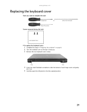
OR - Screw Screw 4 Insert the small flat-blade screwdriver under the bottom of each hinge cover and gently pry it up . 3 Remove the two keyboard cover screws. Phillips #0 screwdriver Screws removed during this task: Flat-blade driver - www.gateway.com Replacing the keyboard cover Tools you need to complete this task: Scribe or non-marring tool 2 black (keyboard cover) To replace the keyboard cover: 1 Complete the steps in "Preparing the notebook" on page 6. 2 Turn the notebook over so the top is facing up . 5 Carefully open the LCD panel to the fully opened position. 29
OR - Screw Screw 4 Insert the small flat-blade screwdriver under the bottom of each hinge cover and gently pry it up . 3 Remove the two keyboard cover screws. Phillips #0 screwdriver Screws removed during this task: Flat-blade driver - www.gateway.com Replacing the keyboard cover Tools you need to complete this task: Scribe or non-marring tool 2 black (keyboard cover) To replace the keyboard cover: 1 Complete the steps in "Preparing the notebook" on page 6. 2 Turn the notebook over so the top is facing up . 5 Carefully open the LCD panel to the fully opened position. 29
8511725 - Gateway Service Guide
Page 34
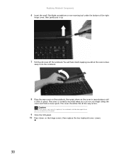
... along the cover and find no loose spots. Caution If the cover is correctly mounted when you can run you try to close the LCD panel. 9 Close the LCD panel. 10 Press down on the hinge covers, then replace the two keyboard cover screws. 30 The cover is not correctly replaced, the...
... along the cover and find no loose spots. Caution If the cover is correctly mounted when you can run you try to close the LCD panel. 9 Close the LCD panel. 10 Press down on the hinge covers, then replace the two keyboard cover screws. 30 The cover is not correctly replaced, the...
8511725 - Gateway Service Guide
Page 36
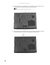
Tip Depending on the end of the cover opposite of the thumb notch. Thumb notch 32 Screws Screws 6 Use the thumb notch to break off the tabs located on your model, not all screws may be removed). Be careful not to lift the memory bay cover, then remove it. Replacing Notebook Components 5 Close the LCD panel, turn the notebook over so the bottom is facing up, then loosen the six memory bay cover screws (these screws cannot be captive.
Tip Depending on the end of the cover opposite of the thumb notch. Thumb notch 32 Screws Screws 6 Use the thumb notch to break off the tabs located on your model, not all screws may be removed). Be careful not to lift the memory bay cover, then remove it. Replacing Notebook Components 5 Close the LCD panel, turn the notebook over so the bottom is facing up, then loosen the six memory bay cover screws (these screws cannot be captive.
8511725 - Gateway Service Guide
Page 37
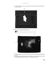
Tip Depending on the keyboard features, one or both of the keyboard raised, carefully push it toward the LCD panel to damage the LCD panel. 33 Screw Screw 9 Turn the notebook over so the top is facing up, then open the LCD panel to the fully opened position. 10 With the back edge of these screws may be removed), then remove the wireless bay cover. Screw 8 Remove the two optional keyboard screws. Be careful not to release the keyboard retaining tabs. www.gateway.com 7 Loosen the wireless bay cover screw (this screw cannot be absent.
Tip Depending on the keyboard features, one or both of the keyboard raised, carefully push it toward the LCD panel to damage the LCD panel. 33 Screw Screw 9 Turn the notebook over so the top is facing up, then open the LCD panel to the fully opened position. 10 With the back edge of these screws may be removed), then remove the wireless bay cover. Screw 8 Remove the two optional keyboard screws. Be careful not to release the keyboard retaining tabs. www.gateway.com 7 Loosen the wireless bay cover screw (this screw cannot be absent.

8511725 - Gateway Service Guide
Page 38
Be careful not to damage the LCD panel. 12 Lift the black keyboard connector clip, then remove the cable. The keyboard is now completely detached from the notebook. 14 Place the new ... any other components. Keyboard connector clip 13 Lift the old keyboard away from the notebook. Replacing Notebook Components 11 Carefully rotate the keyboard toward the LCD panel until the keyboard is almost face-up. 34
Be careful not to damage the LCD panel. 12 Lift the black keyboard connector clip, then remove the cable. The keyboard is now completely detached from the notebook. 14 Place the new ... any other components. Keyboard connector clip 13 Lift the old keyboard away from the notebook. Replacing Notebook Components 11 Carefully rotate the keyboard toward the LCD panel until the keyboard is almost face-up. 34
8511725 - Gateway Service Guide
Page 39
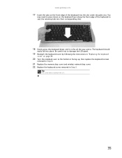
www.gateway.com 17 Insert the tabs on the front edge of the keyboard to seat the retaining tabs into their corresponding slots. 18 Gently press the ... front edge of the keyboard into place. The keyboard should easily fall into the slot under the palm rest. You may need to damage the LCD panel. 19 Reattach the keyboard cover by following the instructions in Step 3.
www.gateway.com 17 Insert the tabs on the front edge of the keyboard to seat the retaining tabs into their corresponding slots. 18 Gently press the ... front edge of the keyboard into place. The keyboard should easily fall into the slot under the palm rest. You may need to damage the LCD panel. 19 Reattach the keyboard cover by following the instructions in Step 3.
8511725 - Gateway Service Guide
Page 40
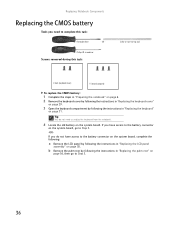
... not have access to the battery connector on the system board, go to the battery connector on the system board, complete the following: a Remove the LCD panel by following the instructions in "Replacing the palm rest" on page 31. Replacing Notebook Components Replacing the CMOS battery Tools you need to unplug...
... not have access to the battery connector on the system board, go to the battery connector on the system board, complete the following: a Remove the LCD panel by following the instructions in "Replacing the palm rest" on page 31. Replacing Notebook Components Replacing the CMOS battery Tools you need to unplug...
8511725 - Gateway Service Guide
Page 41
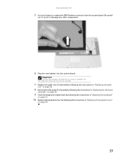
...) by following the instructions in "Replacing the palm rest" on page 56. 8 Remove the LCD panel (if removed) by following the instructions in "Replacing the LCD panel assembly" on page 38. 9 Close the keyboard compartment by following the instructions in "Replacing... the keyboard" on page 31. 10 Replace the keyboard cover by following the instructions in "Replacing the keyboard cover" on page 29. 37 Important Use only CMOS batteries designed for this Gateway notebook. www.gateway...
...) by following the instructions in "Replacing the palm rest" on page 56. 8 Remove the LCD panel (if removed) by following the instructions in "Replacing the LCD panel assembly" on page 38. 9 Close the keyboard compartment by following the instructions in "Replacing... the keyboard" on page 31. 10 Replace the keyboard cover by following the instructions in "Replacing the keyboard cover" on page 29. 37 Important Use only CMOS batteries designed for this Gateway notebook. www.gateway...

8511725 - Gateway Service Guide
Page 42
... assembly Tools you need to complete this task: Scribe or non-marring tool 2 black (keyboard cover) 1-3 black (keyboard) 4 black (LCD panel hinges) To replace the LCD panel assembly: 1 Complete the steps in "Preparing the notebook" on page 6. 2 If the notebook has IEEE 802.11 wireless networking built in "Replacing the keyboard" ...
... assembly Tools you need to complete this task: Scribe or non-marring tool 2 black (keyboard cover) 1-3 black (keyboard) 4 black (LCD panel hinges) To replace the LCD panel assembly: 1 Complete the steps in "Preparing the notebook" on page 6. 2 If the notebook has IEEE 802.11 wireless networking built in "Replacing the keyboard" ...

8511725 - Gateway Service Guide
Page 43
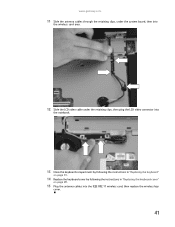
Retaining clips Connector 6 Lift up on the video cable retaining clips slightly, then slide the video cable out from under the clips. 7 Taking care to note the cables' routing and positions as they are installed from Gateway, pull the antenna wires out from under the system board, then slide the wires out from the notebook. www.gateway.com 5 Carefully unplug the LCD video cable from under the retaining clips. 39 Make sure you grasp the connector, not the cable.
Retaining clips Connector 6 Lift up on the video cable retaining clips slightly, then slide the video cable out from under the clips. 7 Taking care to note the cables' routing and positions as they are installed from Gateway, pull the antenna wires out from under the system board, then slide the wires out from the notebook. www.gateway.com 5 Carefully unplug the LCD video cable from under the retaining clips. 39 Make sure you grasp the connector, not the cable.

8511725 - Gateway Service Guide
Page 44
Replacing Notebook Components 8 Remove the four hinge screws that secure the LCD panel to the notebook. Screws 9 Lift the LCD panel assembly away from the notebook. 10 Place the new LCD panel assembly onto the notebook, then replace the four hinge screws. 40 The LCD panel assembly is now completely detached from the notebook.
Replacing Notebook Components 8 Remove the four hinge screws that secure the LCD panel to the notebook. Screws 9 Lift the LCD panel assembly away from the notebook. 10 Place the new LCD panel assembly onto the notebook, then replace the four hinge screws. 40 The LCD panel assembly is now completely detached from the notebook.
8511725 - Gateway Service Guide
Page 45
www.gateway.com 11 Slide the antenna cables through the retaining clips, under the system board, then into the wireless card area. 12 Slide the LCD video cable under the retaining clips, then plug the LCD video connector into the notebook. 13 Close the keyboard compartment by following the instructions in "Replacing the keyboard" on page 31. 14 Replace the keyboard cover by following the instructions in "Replacing the keyboard cover" on page 29. 15 Plug the antenna cables into the IEEE 802.11 wireless card, then replace the wireless bay cover. 41
www.gateway.com 11 Slide the antenna cables through the retaining clips, under the system board, then into the wireless card area. 12 Slide the LCD video cable under the retaining clips, then plug the LCD video connector into the notebook. 13 Close the keyboard compartment by following the instructions in "Replacing the keyboard" on page 31. 14 Replace the keyboard cover by following the instructions in "Replacing the keyboard cover" on page 29. 15 Plug the antenna cables into the IEEE 802.11 wireless card, then replace the wireless bay cover. 41
8511725 - Gateway Service Guide
Page 46
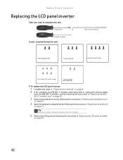
... cover" on page 29. 4 Open the keyboard compartment by following the instructions in "Replacing the LCD panel assembly" on page 31. OR - Replacing Notebook Components Replacing the LCD panel inverter Tools you need to complete this task: Scribe or non-marring tool 2 black (keyboard... cover) 1-3 black (keyboard) 4 black (LCD panel hinges) 4 or 6 chrome (LCD panel assembly) 2 chrome (bracket) Select models only To replace the LCD panel inverter: 1 Complete the steps in "Preparing the notebook" on page 6. 2 If the notebook...
... cover" on page 29. 4 Open the keyboard compartment by following the instructions in "Replacing the LCD panel assembly" on page 31. OR - Replacing Notebook Components Replacing the LCD panel inverter Tools you need to complete this task: Scribe or non-marring tool 2 black (keyboard... cover) 1-3 black (keyboard) 4 black (LCD panel hinges) 4 or 6 chrome (LCD panel assembly) 2 chrome (bracket) Select models only To replace the LCD panel inverter: 1 Complete the steps in "Preparing the notebook" on page 6. 2 If the notebook...
8511725 - Gateway Service Guide
Page 47
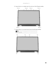
www.gateway.com 6 Remove the four or six rubber inserts from the front of the LCD panel assembly. Rubber insert Rubber insert Rubber insert Rubber insert Rubber insert Rubber insert 7 Remove the four or six screws from the front of the LCD panel assembly. Tip On select models, you may be able to access the inverter by removing only the bottom two screws. Screw Screw Screw Screw Screw Screw 43
www.gateway.com 6 Remove the four or six rubber inserts from the front of the LCD panel assembly. Rubber insert Rubber insert Rubber insert Rubber insert Rubber insert Rubber insert 7 Remove the four or six screws from the front of the LCD panel assembly. Tip On select models, you may be able to access the inverter by removing only the bottom two screws. Screw Screw Screw Screw Screw Screw 43

8511725 - Gateway Service Guide
Page 48
Screw Screw 44 Replacing Notebook Components 8 Carefully separate the front and back of the LCD panel assembly. 9 Locate the inverter. If the inverter is either at the bottom of the LCD panel assembly. Tip If you may need to remove the two screws holding the bracket to the LCD panel assembly, then remove the bracket. Depending on LCD panel size, it is located at the bottom or side of the LCD panel assembly, you only removed the bottom two screws in the previous step, separate only the lower half of the LCD panel assembly.
Screw Screw 44 Replacing Notebook Components 8 Carefully separate the front and back of the LCD panel assembly. 9 Locate the inverter. If the inverter is either at the bottom of the LCD panel assembly. Tip If you may need to remove the two screws holding the bracket to the LCD panel assembly, then remove the bracket. Depending on LCD panel size, it is located at the bottom or side of the LCD panel assembly, you only removed the bottom two screws in the previous step, separate only the lower half of the LCD panel assembly.

8511725 - Gateway Service Guide
Page 49
...by following the instructions in "Replacing the LCD panel assembly" on page 38. 18 Close the keyboard compartment by following the instructions in "Replacing the keyboard" on page 31. 19 Replace the keyboard cover by following the instructions in place. www.gateway.com 10 Unplug both cables from the front... of the LCD panel assembly removed in Step 7. 16 Replace the four or six rubber inserts onto the front of the...
...by following the instructions in "Replacing the LCD panel assembly" on page 38. 18 Close the keyboard compartment by following the instructions in "Replacing the keyboard" on page 31. 19 Replace the keyboard cover by following the instructions in place. www.gateway.com 10 Unplug both cables from the front... of the LCD panel assembly removed in Step 7. 16 Replace the four or six rubber inserts onto the front of the...

8511725 - Gateway Service Guide
Page 50
... need to complete this task: Scribe or non-marring tool 2 black (keyboard cover) 1-3 black (keyboard) 4 black (LCD panel hinges) 4 or 6 chrome (LCD panel assembly) 6 chrome (LCD panel) To replace the LCD panel: 1 Complete the steps in "Preparing the notebook" on page 6. 2 If the notebook has IEEE 802.11 wireless... networking built in, unplug the antenna cables from the notebook. 5 Remove the LCD panel by following the instructions in "Replacing the keyboard" on page 38. 46 Tip You do not need to unplug the keyboard from the ...
... need to complete this task: Scribe or non-marring tool 2 black (keyboard cover) 1-3 black (keyboard) 4 black (LCD panel hinges) 4 or 6 chrome (LCD panel assembly) 6 chrome (LCD panel) To replace the LCD panel: 1 Complete the steps in "Preparing the notebook" on page 6. 2 If the notebook has IEEE 802.11 wireless... networking built in, unplug the antenna cables from the notebook. 5 Remove the LCD panel by following the instructions in "Replacing the keyboard" on page 38. 46 Tip You do not need to unplug the keyboard from the ...


