
Service Guide
Page 9
... HDD Not Operating Correctly 134 USB Failure (Right up/down side 135 Other Failures 135 Intermittent Problems 136 Undetermined Problems 136 POST Code Reference Tables 137 Jumper and Connector Locations 141 Top View 141 Bottom View 142 Clearing Password Check and BIOS Recovery 143...Recovery by Crisis Disk 144 FRU (Field Replaceable Unit) List 147 Gateway LT31 Exploded Diagrams 148 Main Assembly 148 LCD Assembly 149 Gateway LT Series FRU List 150 Model Definition and Configuration 156 Gateway LT31 Series 156 Test Compatible Components 161 Windows XP Environment Test 162...
... HDD Not Operating Correctly 134 USB Failure (Right up/down side 135 Other Failures 135 Intermittent Problems 136 Undetermined Problems 136 POST Code Reference Tables 137 Jumper and Connector Locations 141 Top View 141 Bottom View 142 Clearing Password Check and BIOS Recovery 143...Recovery by Crisis Disk 144 FRU (Field Replaceable Unit) List 147 Gateway LT31 Exploded Diagrams 148 Main Assembly 148 LCD Assembly 149 Gateway LT Series FRU List 150 Model Definition and Configuration 156 Gateway LT31 Series 156 Test Compatible Components 161 Windows XP Environment Test 162...

Service Guide
Page 31
... BIOS Setup Utility is already properly configured and optimized, and you do not need to parameter values. To activate the BIOS Utility, press F2 during POST to run Setup. In this menu, user can change the value of a parameter, press F5 or F6. • A plus sign (+) indicates ...to go to enter setup. Navigation keys for parameters are six menu options: Information, Main, Advanced, Security, Power, Boot, and Exit. Your computer is a hardware configuration program built into your computer's BIOS (Basic Input/ Output System). Press during POST (when Press to different models.
... BIOS Setup Utility is already properly configured and optimized, and you do not need to parameter values. To activate the BIOS Utility, press F2 during POST to run Setup. In this menu, user can change the value of a parameter, press F5 or F6. • A plus sign (+) indicates ...to go to enter setup. Navigation keys for parameters are six menu options: Information, Main, Advanced, Security, Power, Boot, and Exit. Your computer is a hardware configuration program built into your computer's BIOS (Basic Input/ Output System). Press during POST (when Press to different models.

Service Guide
Page 33
... Menu D2D Recovery Description Sets the system time. Sets the system date. Specifies the primary IDE master. Enables, disables Boot Menu during POST. Settings in this screen. The hours are the default and suggested parameter settings. Memory size is for your reference only. The function ...: Enabled or Disabled Option: Enabled or Disabled Option: Enabled or Enabled Option: Enabled or Disabled Chapter 2 23 Allows startup to skip normal POST messages while booting, decreasing the time needed to set the system time and date as well as enable and disable boot option and recovery.
... Menu D2D Recovery Description Sets the system time. Sets the system date. Specifies the primary IDE master. Enables, disables Boot Menu during POST. Settings in this screen. The hours are the default and suggested parameter settings. Memory size is for your reference only. The function ...: Enabled or Disabled Option: Enabled or Disabled Option: Enabled or Enabled Option: Enabled or Disabled Chapter 2 23 Allows startup to skip normal POST messages while booting, decreasing the time needed to set the system time and date as well as enable and disable boot option and recovery.

Service Guide
Page 137
...display is done by pressing Fn+F5. Reconnect the power and reboot the computer. 4. Make sure the computer has power by checking at least one of the following actions one at a time to the computer and switch between the internal display and the external display is by removing the.... 1. No Replace external DDRAM module Replace the main board CPU Thermal Remove and Module properly No replace thermal connected? module No POST or Video If the POST or video doesn't display, perform the following actions one at a time to No Power Power On ? Do not replace non-defective...
...display is done by pressing Fn+F5. Reconnect the power and reboot the computer. 4. Make sure the computer has power by checking at least one of the following actions one at a time to the computer and switch between the internal display and the external display is by removing the.... 1. No Replace external DDRAM module Replace the main board CPU Thermal Remove and Module properly No replace thermal connected? module No POST or Video If the POST or video doesn't display, perform the following actions one at a time to No Power Power On ? Do not replace non-defective...

Service Guide
Page 147
... controller initialization Reset Programmable Interrupt Controller Test DRAM refresh Test 8742 Keyboard Controller Set ES segment register to 4 GB Enable A20 line Autosize DRAM Initialize POST Memory Manager Clear 512 KB base RAM RAM failure on address line xxxx* RAM failure on data bits xxxx* of low byte of memory bus... memory bus Test CPU bus-clock frequency Initialize Phoenix Dispatch Manager Warm start shut down Shadow system BIOS ROM Autosize cache Advanced configuration of the POST process. Code 02h 03h 04h 06h 08h 09h 0Ah 0Bh 0Ch 0Eh 0Fh 10h 11h 12h 13h 14h 16h 17h 18h 1Ah 1Ch 20h 22h...
... controller initialization Reset Programmable Interrupt Controller Test DRAM refresh Test 8742 Keyboard Controller Set ES segment register to 4 GB Enable A20 line Autosize DRAM Initialize POST Memory Manager Clear 512 KB base RAM RAM failure on address line xxxx* RAM failure on data bits xxxx* of low byte of memory bus... memory bus Test CPU bus-clock frequency Initialize Phoenix Dispatch Manager Warm start shut down Shadow system BIOS ROM Autosize cache Advanced configuration of the POST process. Code 02h 03h 04h 06h 08h 09h 0Ah 0Bh 0Ch 0Eh 0Fh 10h 11h 12h 13h 14h 16h 17h 18h 1Ah 1Ch 20h 22h...

Service Guide
Page 148
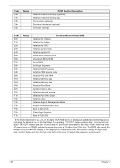
...6Ah 6Bh 6Ch 6Eh 70h 72h 76h 7Ch 7Eh 80h 81h 82h 83h 84h 85h 86h 87h 88h 89h Beeps 2-1-2-3 2-2-3-1 POST Routine Description POST device initialization Check ROM copyright notice Check video configuration against CMOS Initialize PCI bus and devices Initialize all video adapters in ... errors Check for keyboard errors Set up hardware interrupt vectors Initialize coprocessor if present Disable onboard Super I/O ports and IRQs Late POST device initialization Detect and install external RS232 ports Configure non-MCD IDE controllers Detect and install external parallel ports Initialize PC-compatible...
...6Ah 6Bh 6Ch 6Eh 70h 72h 76h 7Ch 7Eh 80h 81h 82h 83h 84h 85h 86h 87h 88h 89h Beeps 2-1-2-3 2-2-3-1 POST Routine Description POST device initialization Check ROM copyright notice Check video configuration against CMOS Initialize PCI bus and devices Initialize all video adapters in ... errors Check for keyboard errors Set up hardware interrupt vectors Initialize coprocessor if present Disable onboard Super I/O ports and IRQs Late POST device initialization Detect and install external RS232 ports Configure non-MCD IDE controllers Detect and install external parallel ports Initialize PC-compatible...

Service Guide
Page 149
...drives Set time of ATA drives (optional) Initialize hard-disk controllers Initialize local-bus hard-disk controllers Jump to boot with INT 19 Initialize POST Error Manager (PEM) Initialize error logging Initialize error display function Initialize system error handler PnPnd dual CMOS (optional) Chapter 4 139 Code 8Ah...AAh ACh AEh B0h B2h B4h B5h B6h B9h BAh BBh BCh BDh BEh BFh C0h C1h C2h C3h C4h C5h Beeps 1-2 1 POST Routine Description Initialize Extended BIOS Data Area Test and initialize PS/2 mouse Initialize floppy controller Determine number of day Check key lock Initialize Typematic...
...drives Set time of ATA drives (optional) Initialize hard-disk controllers Initialize local-bus hard-disk controllers Jump to boot with INT 19 Initialize POST Error Manager (PEM) Initialize error logging Initialize error display function Initialize system error handler PnPnd dual CMOS (optional) Chapter 4 139 Code 8Ah...AAh ACh AEh B0h B2h B4h B5h B6h B9h BAh BBh BCh BDh BEh BFh C0h C1h C2h C3h C4h C5h Beeps 1-2 1 POST Routine Description Initialize Extended BIOS Data Area Test and initialize PS/2 mouse Initialize floppy controller Determine number of day Check key lock Initialize Typematic...
Service Guide
Page 150
Code C6h C7h C8h C9h D2h Beeps POST Routine Description Initialize notebook docking (optional) Initialize notebook docking late Force check (optional) Extended checksum (optional) Unknown interrupt Code E0h E1h E2h E3h E4h E5h ...
Code C6h C7h C8h C9h D2h Beeps POST Routine Description Initialize notebook docking (optional) Initialize notebook docking late Force check (optional) Extended checksum (optional) Unknown interrupt Code E0h E1h E2h E3h E4h E5h ...

Service Guide
Page 154
... should be made by Crisis Disk BIOS Recovery Boot Block: BIOS Recovery Boot Block is enabled, the system will overwrite all data on during BIOS POST. It is strongly recommended to a successful one once the previous BIOS flashing process failed. If this feature to restore the BIOS firmware to have the...
... should be made by Crisis Disk BIOS Recovery Boot Block: BIOS Recovery Boot Block is enabled, the system will overwrite all data on during BIOS POST. It is strongly recommended to a successful one once the previous BIOS flashing process failed. If this feature to restore the BIOS firmware to have the...

Service Guide
Page 178
... 81 Replacing 90 Model Definition 156 N No Display Issue 127 num lock on indicator 8 O ODD Failure 135 Online Support Information 165 P Panel 4 left 4 PC Card 8 POST Codes Reference Tables 137 Power On Failure 126 R RTC Battery Removing 74 Replacing 74, 96 S Speaker Module Removing 63, 104 speakers hotkey 12 System Block...
... 81 Replacing 90 Model Definition 156 N No Display Issue 127 num lock on indicator 8 O ODD Failure 135 Online Support Information 165 P Panel 4 left 4 PC Card 8 POST Codes Reference Tables 137 Power On Failure 126 R RTC Battery Removing 74 Replacing 74, 96 S Speaker Module Removing 63, 104 speakers hotkey 12 System Block...


