
Pilots Guide
Page 4
... avoidance and is not certified for use in applications requiring a certified terrain awareness system. GPS altitude should be considered as an aid to ensure that providing monitoring and/or selftest capability for all redundant or correlated information available in the cockpit. WARNING: The Garmin G500 has a very high degree of the terrain data.
... avoidance and is not certified for use in applications requiring a certified terrain awareness system. GPS altitude should be considered as an aid to ensure that providing monitoring and/or selftest capability for all redundant or correlated information available in the cockpit. WARNING: The Garmin G500 has a very high degree of the terrain data.

Pilots Guide
Page 6
.... NOTE: All visual depictions contained within this document, including screen images of the Garmin G500 utilize GPS as safe for anti-reflective coatings. B Sec 6 Symbols Sec 7 Appendix A Glossary Sec 8 Index Appendix B iv Garmin G500 Pilot's Guide 190-01102-02 Rev. CAUTION: The Garmin G500 does not contain any interference received, including interference that may not reflect the...
.... NOTE: All visual depictions contained within this document, including screen images of the Garmin G500 utilize GPS as safe for anti-reflective coatings. B Sec 6 Symbols Sec 7 Appendix A Glossary Sec 8 Index Appendix B iv Garmin G500 Pilot's Guide 190-01102-02 Rev. CAUTION: The Garmin G500 does not contain any interference received, including interference that may not reflect the...

Pilots Guide
Page 17
...largeformat displays. B Garmin G500 Pilot's Guide 1-1 Appendix B Index In normal operating mode, the Primary Flight Display (PFD) presents graphical flight instrumentation (attitude, heading, airspeed, altitude, vertical speed), replacing the traditional flight instrument cluster. GMU 44 Magnetometer GPS Navigator(s) Temperature ... GTX330/330D SL 30 ADF Traffic GWX 68 GAD 43 Figure 1-1 G500 System (LRU Configuration) The system consists of the G500 Avionics Display System. The G500 system is an integrated display system that presents primary flight instrumentation, navigation...
...largeformat displays. B Garmin G500 Pilot's Guide 1-1 Appendix B Index In normal operating mode, the Primary Flight Display (PFD) presents graphical flight instrumentation (attitude, heading, airspeed, altitude, vertical speed), replacing the traditional flight instrument cluster. GMU 44 Magnetometer GPS Navigator(s) Temperature ... GTX330/330D SL 30 ADF Traffic GWX 68 GAD 43 Figure 1-1 G500 System (LRU Configuration) The system consists of the G500 Avionics Display System. The G500 system is an integrated display system that presents primary flight instrumentation, navigation...
Pilots Guide
Page 18
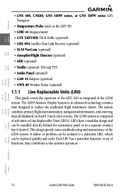
Each LRU has a particular function, or set of the G500 system. B Foreword System Sec 1 PFD Sec 2 MFD Sec 3 Features Avoidance Hazard • GNS 480, CNX80, GNS 400W series, or GNS 500W series GPS Navigator • Temperature Probe (such as integrated in a separate avionics ...contributes to a particular LRU, which can be installed directly behind the instrument panel or in the G500 system. Sec 6 Symbols Sec 7 Appendix A Glossary Sec 8 Index Appendix B 1-2 Garmin G500 Pilot's Guide 190-01102-02 Rev. A failure or problem can be replaced quickly and easily. ...
Each LRU has a particular function, or set of the G500 system. B Foreword System Sec 1 PFD Sec 2 MFD Sec 3 Features Avoidance Hazard • GNS 480, CNX80, GNS 400W series, or GNS 500W series GPS Navigator • Temperature Probe (such as integrated in a separate avionics ...contributes to a particular LRU, which can be installed directly behind the instrument panel or in the G500 system. Sec 6 Symbols Sec 7 Appendix A Glossary Sec 8 Index Appendix B 1-2 Garmin G500 Pilot's Guide 190-01102-02 Rev. A failure or problem can be replaced quickly and easily. ...

Pilots Guide
Page 20
...models in the GRS 77 and in the Navigation Database are compared, and if the IGRF model in the GRS 77. Figure 1-5 GMU 44 Magnetometer 1-4 Garmin G500 Pilot's Guide 190-01102-02 Rev. Actual attitude and heading information is sent to update the IGRF model in the GRS 77 is out of... the Navigation Database. The unit contains advanced tilt sensors, accelerometers, and rate sensors. B Appendix A Glossary Sec 8 Index Appendix B The GRS 77 also utilizes GPS data forwarded from the GRS 77 and communicates with both the GDC 74A Air Data Computer and the GMU 44 magnetometer.
...models in the GRS 77 and in the Navigation Database are compared, and if the IGRF model in the GRS 77. Figure 1-5 GMU 44 Magnetometer 1-4 Garmin G500 Pilot's Guide 190-01102-02 Rev. Actual attitude and heading information is sent to update the IGRF model in the GRS 77 is out of... the Navigation Database. The unit contains advanced tilt sensors, accelerometers, and rate sensors. B Appendix A Glossary Sec 8 Index Appendix B The GRS 77 also utilizes GPS data forwarded from the GRS 77 and communicates with both the GDC 74A Air Data Computer and the GMU 44 magnetometer.

Pilots Guide
Page 23
... PFD Sec 3 MFD Sec 4 Hazard Avoidance Features Sec 5 Additional Sec 6 Annun. & Alerts Figure 1-10 GWX 68 Weather Radar 1.1.11 Garmin Navigator Interface The G500 system requires connection to the MFD. AHRS no-Mag/ Mag Mode no-Air Mode Heading Invalid AHRS no - Attitude and heading information is not... Foreword 1.1.10 GWX 68 Weather Radar The GWX 68 provides airborne weather and ground mapped radar data to at least one external Garmin WAAS GPS navigator, such as the 400W/500W series or GNS 480. 1.1.12 Attitude Heading Reference System (AHRS) NOTE: Aggressive maneuvering while...
... PFD Sec 3 MFD Sec 4 Hazard Avoidance Features Sec 5 Additional Sec 6 Annun. & Alerts Figure 1-10 GWX 68 Weather Radar 1.1.11 Garmin Navigator Interface The G500 system requires connection to the MFD. AHRS no-Mag/ Mag Mode no-Air Mode Heading Invalid AHRS no - Attitude and heading information is not... Foreword 1.1.10 GWX 68 Weather Radar The GWX 68 provides airborne weather and ground mapped radar data to at least one external Garmin WAAS GPS navigator, such as the 400W/500W series or GNS 480. 1.1.12 Attitude Heading Reference System (AHRS) NOTE: Aggressive maneuvering while...

Pilots Guide
Page 24
... in the lower SD card slot. Sec 5 & Alerts Annun. Sec 6 Symbols Sec 7 Appendix A Glossary Sec 8 Index Appendix B 1-8 Garmin G500 Pilot's Guide 190-01102-02 Rev. NOTE: In this case the magnetic standby compass and GPS ground track can be used ; B Foreword System Sec 1 PFD Sec 2 MFD Sec 3 Features Avoidance Hazard Sec 4 Additional Loss...
... in the lower SD card slot. Sec 5 & Alerts Annun. Sec 6 Symbols Sec 7 Appendix A Glossary Sec 8 Index Appendix B 1-8 Garmin G500 Pilot's Guide 190-01102-02 Rev. NOTE: In this case the magnetic standby compass and GPS ground track can be used ; B Foreword System Sec 1 PFD Sec 2 MFD Sec 3 Features Avoidance Hazard Sec 4 Additional Loss...

Pilots Guide
Page 28
... (NAV1, GPS1, ADF, or None). SYN VIS The SYN VIS soft key is available if Synthetic Vision Technology™ is configured for a second GPS or VOR/ LOC. The AP TEST soft key disengages the autopilot as the active navigation source. Sec 5 & Alerts Annun. GPS1 and GPS2 or ... key will only be present if the system is not available for all installations. Sec 6 Symbols Sec 7 Appendix A Glossary Sec 8 Index Appendix B 1-12 Garmin G500 Pilot's Guide 190-01102-02 Rev. The BRG2 soft key will only be present if the system is installed and providing attitude to an autopilot...
... (NAV1, GPS1, ADF, or None). SYN VIS The SYN VIS soft key is available if Synthetic Vision Technology™ is configured for a second GPS or VOR/ LOC. The AP TEST soft key disengages the autopilot as the active navigation source. Sec 5 & Alerts Annun. GPS1 and GPS2 or ... key will only be present if the system is not available for all installations. Sec 6 Symbols Sec 7 Appendix A Glossary Sec 8 Index Appendix B 1-12 Garmin G500 Pilot's Guide 190-01102-02 Rev. The BRG2 soft key will only be present if the system is installed and providing attitude to an autopilot...

Pilots Guide
Page 33
... Foreword Sec 1 System Sec 2 PFD Sec 3 MFD Sec 4 Hazard Avoidance Features Sec 5 Additional Figure 1-18 - When the interfaced GPS unit has acquired a sufficient number of options for functions in the GRS 77. Autopilot Automatically Disconnected Fly the aircraft manually and crosscheck the...has a dedicated MENU key that when pressed displays a context-sensitive list of satellites to update the IGRF model in the MFD. B Garmin G500 Pilot's Guide 1-17 This options list allows 190-01102-02 Rev. The IGRF model is part of attitude information (airspeed, heading, ...
... Foreword Sec 1 System Sec 2 PFD Sec 3 MFD Sec 4 Hazard Avoidance Features Sec 5 Additional Figure 1-18 - When the interfaced GPS unit has acquired a sufficient number of options for functions in the GRS 77. Autopilot Automatically Disconnected Fly the aircraft manually and crosscheck the...has a dedicated MENU key that when pressed displays a context-sensitive list of satellites to update the IGRF model in the MFD. B Garmin G500 Pilot's Guide 1-17 This options list allows 190-01102-02 Rev. The IGRF model is part of attitude information (airspeed, heading, ...

Pilots Guide
Page 39
... Selection Crossfill for CDI and Baro Corrections must be reflected in OBS mode, any course changes will be selected in Aux mode in both GDUs. B Garmin G500 Pilot's Guide 1-23 Foreword Sec 1 System Sec 2 PFD Sec 3 MFD Sec 4 Hazard Avoidance Features When the CDI is in the "Synchronization" box. Figure ...to highlight "CDI" or "BARO" in OBS mode, any changes to the selected CDI on both units. 1) While viewing the first page of GPS or VOR/LOC as the active navigation source. If the pilot selects GPS1 on the CDI and GNS1 is synchronized, any course changes will change...
... Selection Crossfill for CDI and Baro Corrections must be reflected in OBS mode, any course changes will be selected in Aux mode in both GDUs. B Garmin G500 Pilot's Guide 1-23 Foreword Sec 1 System Sec 2 PFD Sec 3 MFD Sec 4 Hazard Avoidance Features When the CDI is in the "Synchronization" box. Figure ...to highlight "CDI" or "BARO" in OBS mode, any changes to the selected CDI on both units. 1) While viewing the first page of GPS or VOR/LOC as the active navigation source. If the pilot selects GPS1 on the CDI and GNS1 is synchronized, any course changes will change...

Pilots Guide
Page 42
... Appendix B 2-2 Garmin G500 Pilot's Guide 190-01102-02 Rev. The true airspeed is displayed in six seconds, if the current rate of acceleration is displayed inside the black pointer. Foreword System Sec 1 PFD Sec 2 MFD Sec 3 2.1 PFD Soft Key Map AP TEST CDI 1-2 PFD GPS Source 1 BRG ...1 VOR/ILS Source 2 NAV 1 GPS 1 SYN VIS SYN TERR HRZN HDG BRG 2 NAV 2 GPS 2 Figure 2-3 PFD Soft Key Diagram 2.2 Airspeed Indicator ADF APTSIGNS ADF The Airspeed Indicator displays airspeed ...
... Appendix B 2-2 Garmin G500 Pilot's Guide 190-01102-02 Rev. The true airspeed is displayed in six seconds, if the current rate of acceleration is displayed inside the black pointer. Foreword System Sec 1 PFD Sec 2 MFD Sec 3 2.1 PFD Soft Key Map AP TEST CDI 1-2 PFD GPS Source 1 BRG ...1 VOR/ILS Source 2 NAV 1 GPS 1 SYN VIS SYN TERR HRZN HDG BRG 2 NAV 2 GPS 2 Figure 2-3 PFD Soft Key Diagram 2.2 Airspeed Indicator ADF APTSIGNS ADF The Airspeed Indicator displays airspeed ...

Pilots Guide
Page 54
... Symbol 6 Course Deviation Indicator (CDI) 7 Rotating Compass Card 8 OBS Mode Active 9 Lateral Deviation Scale 10 GPS Level of the HSI, and the current ground track is present on Navigator Figure 2-23 Horizontal Situation Indicator (HSI) 2-14 Garmin G500 Pilot's Guide 190-01102-02 Rev. Major tick marks are at 10º intervals and...
... Symbol 6 Course Deviation Indicator (CDI) 7 Rotating Compass Card 8 OBS Mode Active 9 Lateral Deviation Scale 10 GPS Level of the HSI, and the current ground track is present on Navigator Figure 2-23 Horizontal Situation Indicator (HSI) 2-14 Garmin G500 Pilot's Guide 190-01102-02 Rev. Major tick marks are at 10º intervals and...

Pilots Guide
Page 56
... valid, the CDI is located directly above the rotating compass card. Sec 6 Symbols Sec 7 Appendix A Glossary Sec 8 Index Appendix B Figure 2-26 Course Deviation Indicator 2-16 Garmin G500 Pilot's Guide 190-01102-02 Rev. Foreword System Sec 1 PFD Sec 2 MFD Sec 3 Features Avoidance Hazard Sec 4 2.6.2 Turn Rate Indicator The Turn Rate Indicator is...
... valid, the CDI is located directly above the rotating compass card. Sec 6 Symbols Sec 7 Appendix A Glossary Sec 8 Index Appendix B Figure 2-26 Course Deviation Indicator 2-16 Garmin G500 Pilot's Guide 190-01102-02 Rev. Foreword System Sec 1 PFD Sec 2 MFD Sec 3 Features Avoidance Hazard Sec 4 2.6.2 Turn Rate Indicator The Turn Rate Indicator is...

Pilots Guide
Page 57
... NAV (VOR, and LOC). If the CDI exceeds the maximum deviation on the scale (two dots) while coupled to GPS. GPS Navigator 1 GPS Navigator 2 VLOC Navigator 1 VLOC Navigator 2 Sec 4 Hazard Avoidance Features Sec 5 Additional Sec 6 Annun. & Alerts Sec 7 Symbols Sec 8 Glossary Appendix A ...190-01102-02 Rev. Color indicates the current navigation source: magenta (for GPS) or green (for VOR and LOC). When coupled to a VOR or localizer (LOC), the CDI has the same angular limits as a mechanical CDI. B Garmin G500 Pilot's Guide 2-17 Foreword Sec 1 System Sec 2 PFD Sec 3...
... NAV (VOR, and LOC). If the CDI exceeds the maximum deviation on the scale (two dots) while coupled to GPS. GPS Navigator 1 GPS Navigator 2 VLOC Navigator 1 VLOC Navigator 2 Sec 4 Hazard Avoidance Features Sec 5 Additional Sec 6 Annun. & Alerts Sec 7 Symbols Sec 8 Glossary Appendix A ...190-01102-02 Rev. Color indicates the current navigation source: magenta (for GPS) or green (for VOR and LOC). When coupled to a VOR or localizer (LOC), the CDI has the same angular limits as a mechanical CDI. B Garmin G500 Pilot's Guide 2-17 Foreword Sec 1 System Sec 2 PFD Sec 3...

Pilots Guide
Page 58
...5 & Alerts Annun. Foreword System Sec 1 PFD Sec 2 1) Press the CDI soft key to toggle between GPS and VOR/LOC source type. 2) Press 1-2 soft key to toggle between the 1 and 2 navigators of the GPS or VOR/ LOC sources. 3) Verify the navigation source by the indication on the HSI and in... Course The Selected Course is shown to the upper left of the PFD. Sec 6 Symbols Sec 7 Appendix A Glossary Sec 8 Index Appendix B 2-18 Garmin G500 Pilot's Guide 190-01102-02 Rev. NOTE: The selected navigator is the active navigator for all PFD and MFD operations, except for 10 seconds after...
...5 & Alerts Annun. Foreword System Sec 1 PFD Sec 2 1) Press the CDI soft key to toggle between GPS and VOR/LOC source type. 2) Press 1-2 soft key to toggle between the 1 and 2 navigators of the GPS or VOR/ LOC sources. 3) Verify the navigation source by the indication on the HSI and in... Course The Selected Course is shown to the upper left of the PFD. Sec 6 Symbols Sec 7 Appendix A Glossary Sec 8 Index Appendix B 2-18 Garmin G500 Pilot's Guide 190-01102-02 Rev. NOTE: The selected navigator is the active navigator for all PFD and MFD operations, except for 10 seconds after...

Pilots Guide
Page 59
...workload during localizer backcourse approaches. Vertical Deviation Source Vertical Deviation Indicator Sec 7 Symbols Sec 8 Glossary Appendix A Figure 2-30 Vertical Deviation Indicator (GPS Source) Appendix B Index 190-01102-02 Rev. Foreword Sec 1 System 2.7.3 Vertical Deviation Indicator (VDI) The Vertical Deviation (Glideslope) Indicator (...an approach of the VSI whenever an ILS frequency is tuned in the active NAV field. B Garmin G500 Pilot's Guide 2-19 This prevents the glideslope from being displayed during approach. A green diamond acts as a magenta diamond.
...workload during localizer backcourse approaches. Vertical Deviation Source Vertical Deviation Indicator Sec 7 Symbols Sec 8 Glossary Appendix A Figure 2-30 Vertical Deviation Indicator (GPS Source) Appendix B Index 190-01102-02 Rev. Foreword Sec 1 System 2.7.3 Vertical Deviation Indicator (VDI) The Vertical Deviation (Glideslope) Indicator (...an approach of the VSI whenever an ILS frequency is tuned in the active NAV field. B Garmin G500 Pilot's Guide 2-19 This prevents the glideslope from being displayed during approach. A green diamond acts as a magenta diamond.

Pilots Guide
Page 62
...with the Corresponding Approach Plate 2.8 Supplemental Flight Data 2.8.1 Bearing Pointers Two Bearing Pointers can be configured for a second navigation source to show : • Bearing source (GPS, NAV, or ADF) • Pointer icon (BRG1 = single line, BRG2 = double line) The Bearing Pointer is removed from the HSI if: • ...The NAV radio is not receiving the tuned VOR station • The NAV radio is tuned to 313° for NAV and GPS sources. Foreword System Sec 1 Course Pointer slewed to a Localizer frequency 2-22 Garmin G500 Pilot's Guide 190-01102-02 Rev.
...with the Corresponding Approach Plate 2.8 Supplemental Flight Data 2.8.1 Bearing Pointers Two Bearing Pointers can be configured for a second navigation source to show : • Bearing source (GPS, NAV, or ADF) • Pointer icon (BRG1 = single line, BRG2 = double line) The Bearing Pointer is removed from the HSI if: • ...The NAV radio is not receiving the tuned VOR station • The NAV radio is tuned to 313° for NAV and GPS sources. Foreword System Sec 1 Course Pointer slewed to a Localizer frequency 2-22 Garmin G500 Pilot's Guide 190-01102-02 Rev.

Pilots Guide
Page 63
...source 2 (BRG2) will be a single line. B Garmin G500 Pilot's Guide 2-23 The Bearing Line for navigation source 1 (BRG1) will be a double line. 190-01102-02 Rev. Foreword Sec 1 System Sec 2 PFD Sec 3 MFD • GPS is the bearing source and an active waypoint is not ... supports a valid flag then the bearing pointer will be displayed, regardless of ADF signal validity.) Bearing 2 Pointer Current Navigation Source CDI GPS Level of Service Bearing 1 Pointer Bearing 1 Source Bearing 1 Pointer Icon Bearing 2 Pointer Icon Figure 2-33 HSI with Bearing Information Bearing...
...source 2 (BRG2) will be a single line. B Garmin G500 Pilot's Guide 2-23 The Bearing Line for navigation source 1 (BRG1) will be a double line. 190-01102-02 Rev. Foreword Sec 1 System Sec 2 PFD Sec 3 MFD • GPS is the bearing source and an active waypoint is not ... supports a valid flag then the bearing pointer will be displayed, regardless of ADF signal validity.) Bearing 2 Pointer Current Navigation Source CDI GPS Level of Service Bearing 1 Pointer Bearing 1 Source Bearing 1 Pointer Icon Bearing 2 Pointer Icon Figure 2-33 HSI with Bearing Information Bearing...

Pilots Guide
Page 65
...set for Navigation Map page 1 are used as a magenta line on the Navigation Map at the location corresponding to the calculated present position. B Garmin G500 Pilot's Guide 3-1 Appendix B Index The Navigation Map can be oriented four different ways: North Up (NORTH UP), Track Up (TRACK UP), ...XM weather subscription or the GWX 68 Weather Radar). The leg of the aircraft icon is shown on information received from the currently selected GPS navigator. The aircraft position and the flight plan legs are shown in white. 190-01102-02 Rev. Foreword Sec 1 System 3 Multi...
...set for Navigation Map page 1 are used as a magenta line on the Navigation Map at the location corresponding to the calculated present position. B Garmin G500 Pilot's Guide 3-1 Appendix B Index The Navigation Map can be oriented four different ways: North Up (NORTH UP), Track Up (TRACK UP), ...XM weather subscription or the GWX 68 Weather Radar). The leg of the aircraft icon is shown on information received from the currently selected GPS navigator. The aircraft position and the flight plan legs are shown in white. 190-01102-02 Rev. Foreword Sec 1 System 3 Multi...

Pilots Guide
Page 131
... B Index 190-01102-02 Rev. In this manner, TERRAIN Proximity can provide advanced alerts of the aircraft. B Garmin G500 Pilot's Guide 4-3 Terrain may be displayed on the Map page group Navigation Map and Terrain pages. GPS-MSL altitude accuracy is affected by factors such as a standard feature of GDU 620 to increase situational...
... B Index 190-01102-02 Rev. In this manner, TERRAIN Proximity can provide advanced alerts of the aircraft. B Garmin G500 Pilot's Guide 4-3 Terrain may be displayed on the Map page group Navigation Map and Terrain pages. GPS-MSL altitude accuracy is affected by factors such as a standard feature of GDU 620 to increase situational...


